Project 1 - Meshing of Floor Panel
Project_1
(floor meshing)
objective
1 . The generated mesh must be exported into Optistruct (.fem) or Radioss (.rad) format.
2. The Mid-surface and the Original Geometry (Parent Component) must be attached as a CAD file (.iges or .stp).
Target Element Length = 5 Units
|
Quality Criteria |
Value |
|
|
1 |
Aspect Ratio |
5 |
|
2 |
Skewness |
45 |
|
3 |
Warping |
15 |
|
4 |
Taper |
0.5 |
|
5 |
Min. Length |
2 Units |
|
6 |
Max. Length |
8 Units |
|
7 |
Min angle Quad |
45 |
|
8 |
Max angle Quad |
135 |
|
9 |
Min angle Tria |
20 |
|
10 |
Max angle Tria |
120 |
|
10 |
Tria % |
10 |
Cad model image: -
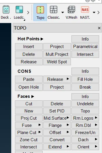
After importing the cad we will set the perimeters and macro length to 1(switch to classic mesh module-in perimeters select length-then choose perimeters to 1 and macro to 1), so that we can geometry can be proper shape.
And also make sure surfaces are oriented properly(Topo module-in faces choose orient)
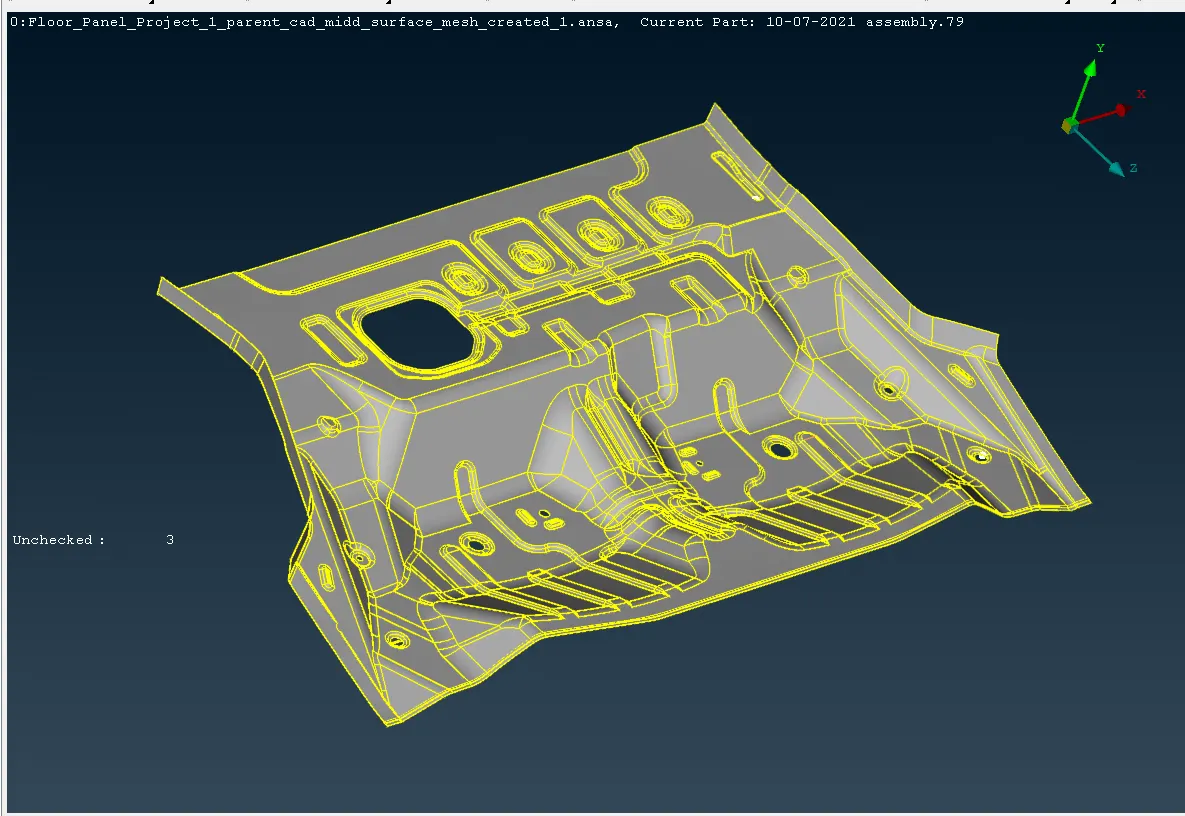
FE model for the above sheet metal component: -.
· Geometry checks:
Before ging for modelling process, we should do geometry checks like cracks between surfaces, unnecessary triple cons etc.
This can be done in Ansa using geometry checks option (geometry checks-choose errors need to hillite - Execute) as follow.
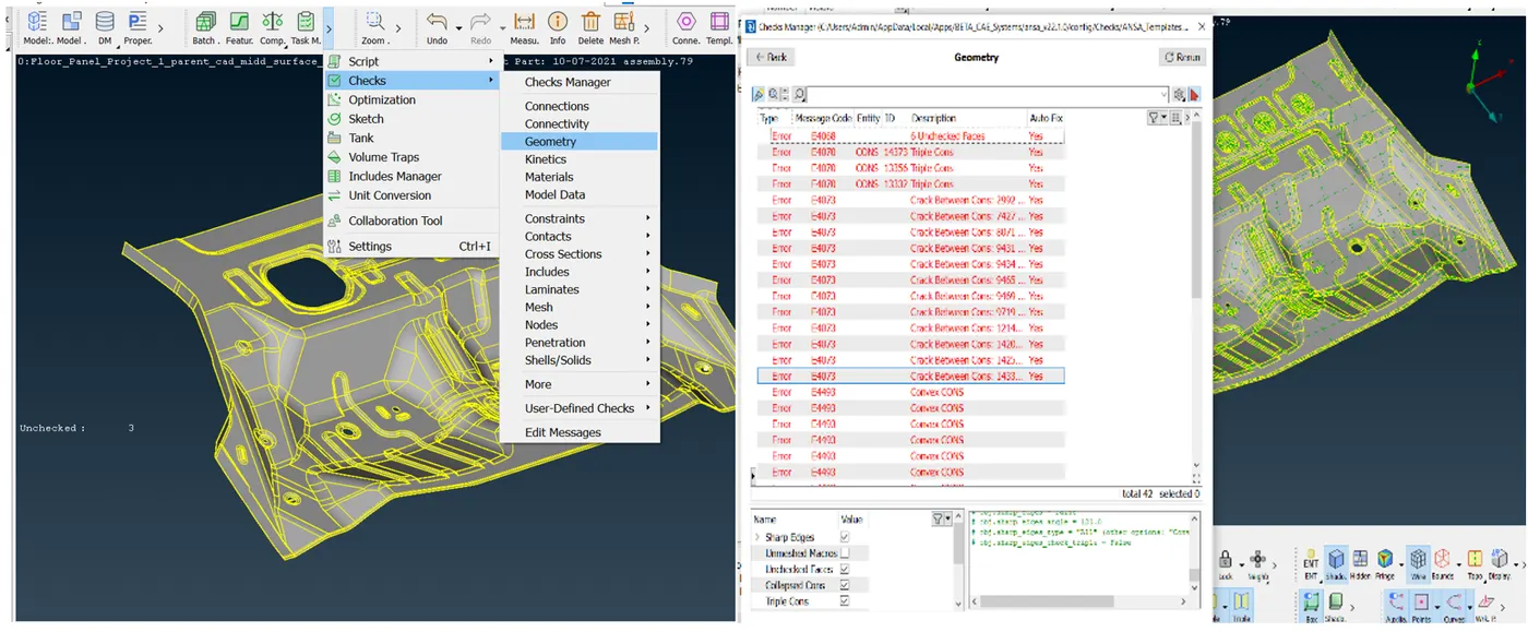
Fig:3 Fig:4
From
above picture we can observe that almost all errors can be cleared
automatically, (fix by Ansa by selecting the errors which showing yes in auto
fix column).
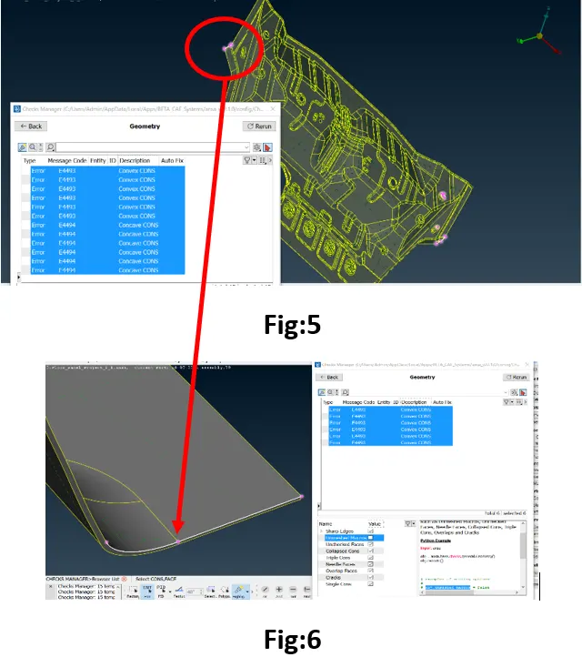
There fore from above picture we can say that convex curves are not an error. So, we can neglect that error.
Midsurface creation: -
First, we need to check for thickness variations in the component so that we can conform the component is sheet metal or plastic.
Heare the component has uniform thickness 1mm thought. we consider this component as sheet metal.
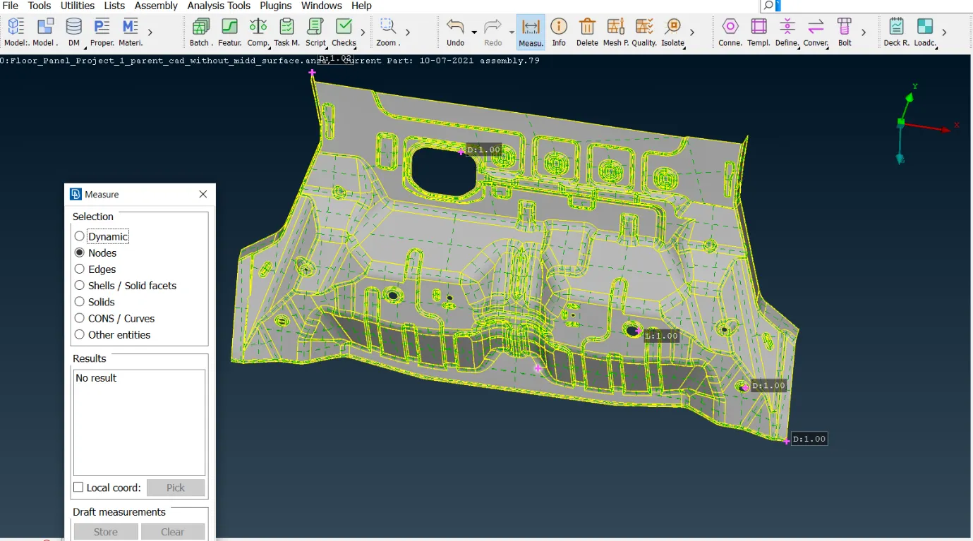
Fig:-7
we use offset option to create midsurface because the parent surface has more surface errors which are cannot be find while geometry check.
Without clearing those errors, we cannot use automatic options for generating midsurface.
Eg:-
1.Midsurface-skin-select component (mid mouse click)
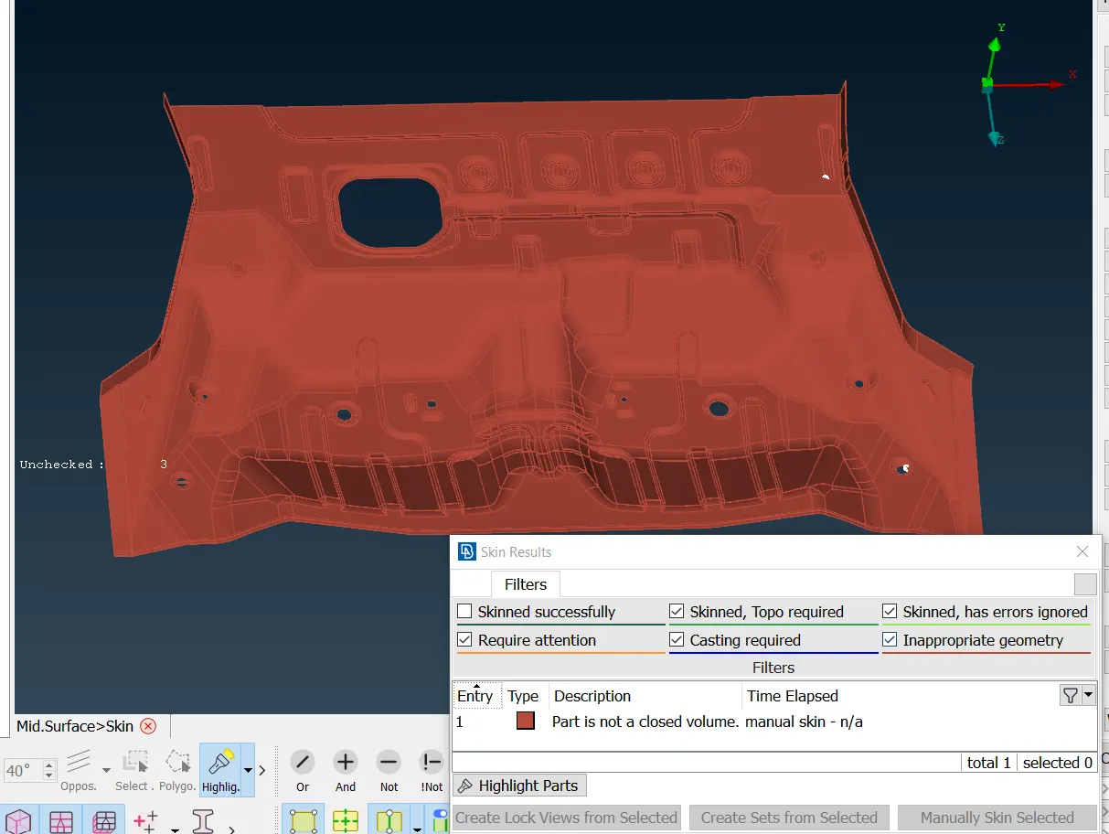
Fig:-8
2. middle (multi) option:-
This option takes more time because of large surface area for differentiating red, green and blue which represents upper, bottom and thickness area of component. And so, the surface errors making the process complex to use this option.
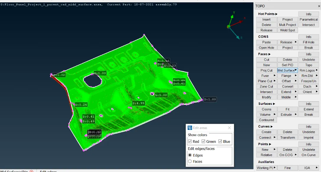
Fig:-9
Midsurface with offset option:-
Topo module- offset ( in faces)-select faces-enter the offset value according to the normal of the faces as shown below -set the PID option to auto create or ask always-conform by selecting OK.
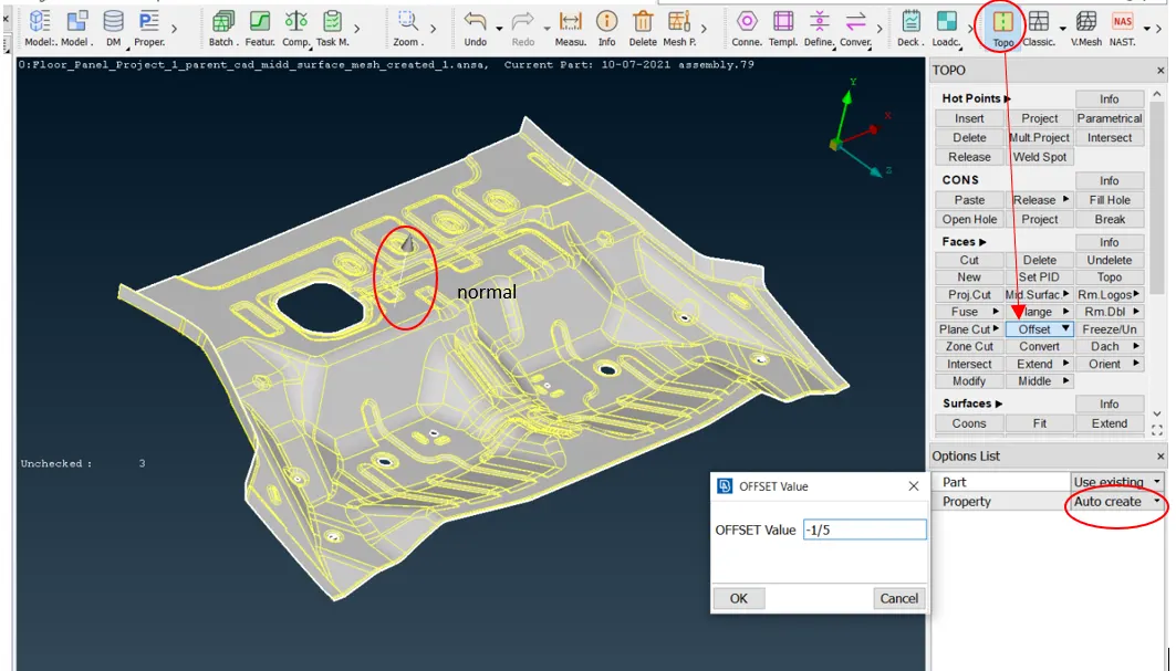
Fig:-10
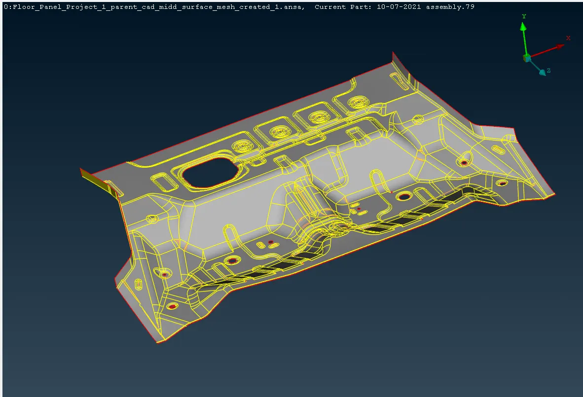
Fig:-11
Geometry check for middsurface :-
After creating midd surface, geometry check needs to do to find the surface errors and unnecessary pasting of surfaces which result in triple cons etc.
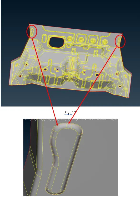
In above figure we will find triple con and also the length of fillet is very less (less than minimum element size2mm). so, the cons are merge with following surface.
Also in some areas cons are adjusted to meet with quality criteria without loosing features and mesh flow.
some examples are shown bellow
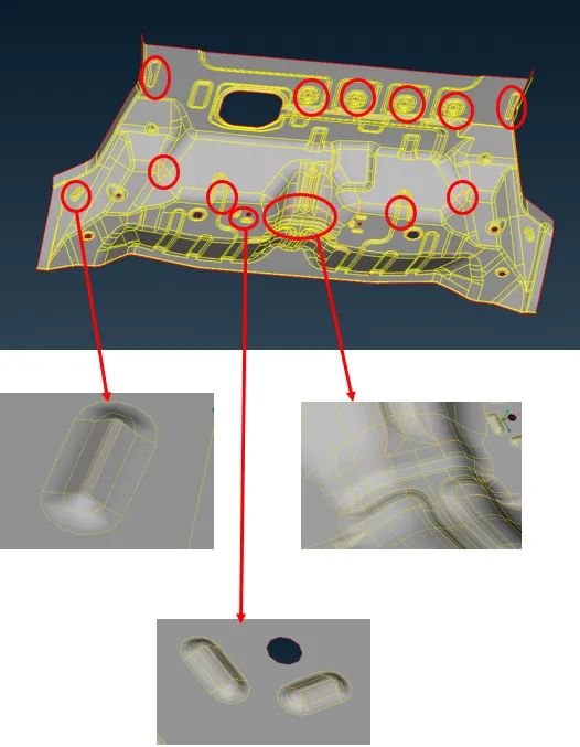
Mesh creation: -
Before creating mesh, we need to set perimeter and macro length equal to average element size (hear in this case 5mm) as shown on starting.
Then I have used best mesh for automatic mesh creation (classic mesh module-select best mesh-then select surfaces to mesh-conform it by kicking middle mouse button).
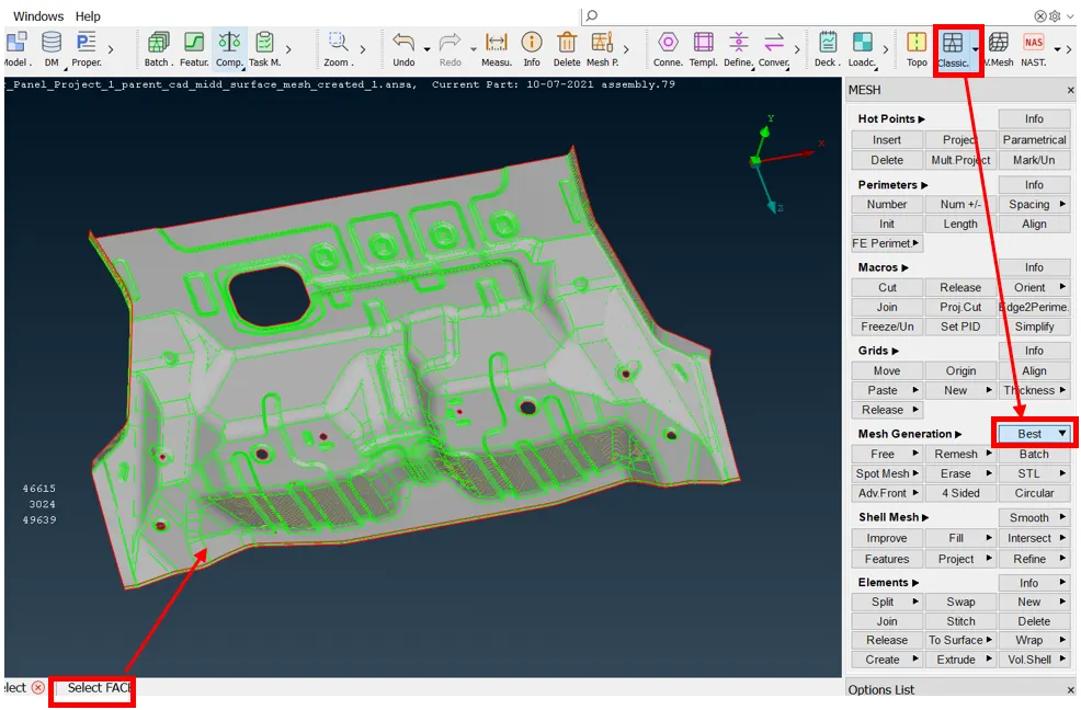
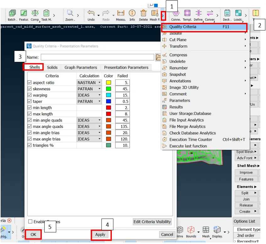
Then set quality criteria of mesh as follows
Down arrow (if quality criteria icon visible) -select quality criteria (or press F11)-go to shells section and enter the criteria values as shown below -then apply-ok.
|
S.N |
Quality Criteria |
Value |
|
1 |
Aspect Ratio |
5 |
|
2 |
Skewness |
45 |
|
3 |
Warping |
15 |
|
4 |
Taper |
0.5 |
|
5 |
Min. Length |
2 Units |
|
6 |
Max. Length |
8 Units |
|
7 |
Min angle Quad |
45 |
|
8 |
Max angle Quad |
135 |
|
9 |
Min angle Tria |
20 |
|
10 |
Max angle Tria |
120 |
|
10 |
Tria % |
10 |
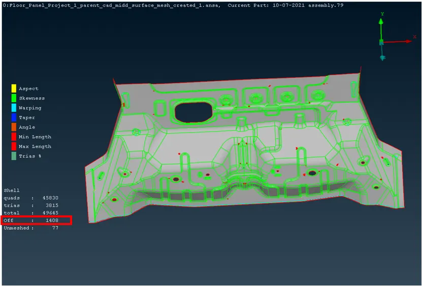
There fore we can find the elements that are not meeting the criteria as follows :-
In below pic the box highlighting number of off elements are the elements not meeting the criteria.
There by adjusting the mesh ,curves and remeshing the surface we can clear the errors.
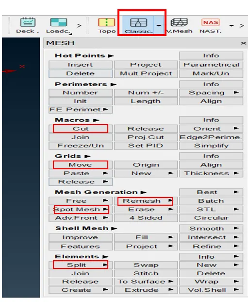
As shown in above picture
CUT: - in macro-CUT option is used to merge two adjacent surfaces by right clicking on it which helps in clearing elements not meeting minimum element size(2mm) and use to make CUT on surfaces to maintain element size and flow.
MOVE: - grid-move option used in eliminating skewness in elements by moving nodes.
SPOT MESH:- MESH GENARATION-SPOT MESH is used to crate meah in localized areaof surfaces after ceating cut which automatically erraze the mesh on editted surfaces.
SPLIT OPTION:- ELEMENTS- SPLIT option is used in edditing elements in locally to maintain quality and tria flow etc.
REMESH: - REMESH option is helps in maintaining flow and eliminating maximum element size majorly.
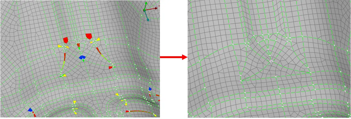
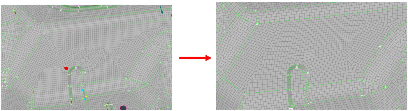
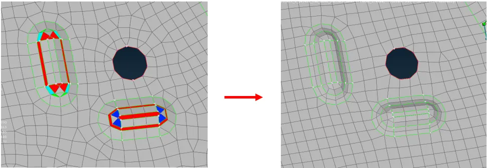
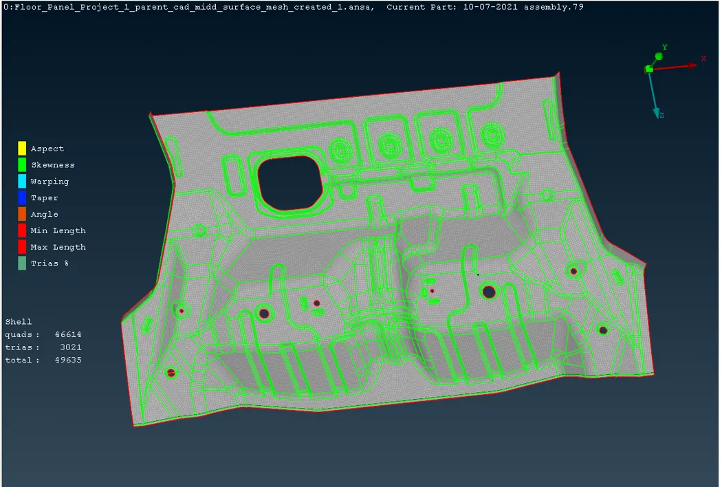
Final mesh: -
Assigning thickness to 2D(shell) elements:-
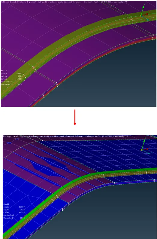
Below component has thickness 1mm but in one location thickness is 2mm therefore PID’S are created accordingly.
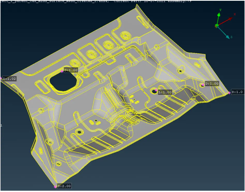
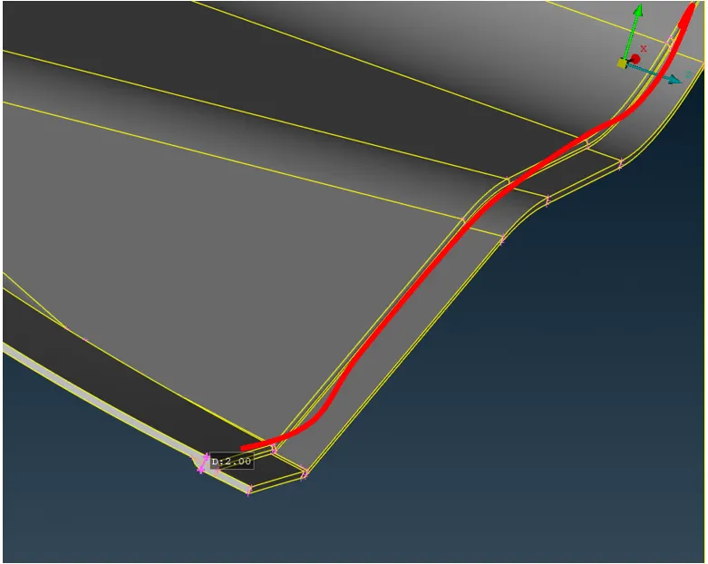
Above line area has thickness 2mm.
PID creation:-
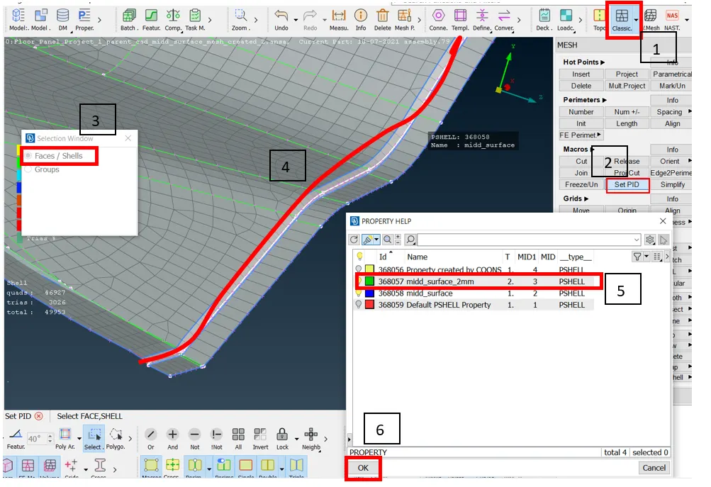
Classic mesh- set PID- in faces/shell-select faces of elements- select the PID created -double click on created PID to assign the elements-ok.
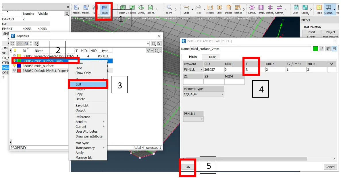
Assigns thickness: -
Right click on the PID to change thickness in T section change thickness(2mm) then select ok to conform.
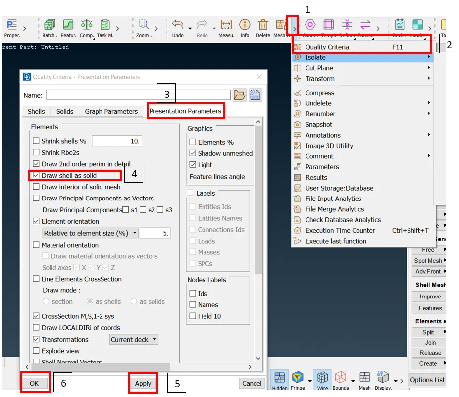
To visualize thickness, follow the steps bellow
As mentioned above open the quality criteria tab in that click on presentation parameters in that check shell as 2D.
NOTE: -
Because of file size issue files are shared in zip file format in with different files. Please find the file required format in zip file.
· Floor_Panel_Project_1_midd_surface_and_mesh (zip file include .Ansa of midd surface and mesh).
· Floor_Panel_Project_1_midd_surfaceS2 (zip file include .stp file of midd surface).
· Floor_Panel_Project_1_parent_cad_midd_surface_mesh_created_2 (this zip file include .FEM file).
· Floor_Panel_Project_1_parent_cadA1 (zip file include parent cad in .step format).