Meshing of Floor Panel in ANSA.
Aim:
To Mesh the given CAD Model.
Objective:
Check for the Geometry clean-up (if required).
Take the mid surface for all the components after checking the geometrical errors.
Mesh the mid surface with the given element Quality criteria. (Refer the table Below for the Quality criteria).
The features in the model have to be captured properly with good mesh flow.
Assign the thickness to the model surface.
|
Sl. No. |
Quality Criteria |
Value |
|
1 |
Aspect Ratio |
5 |
|
2 |
Skewness |
45 |
|
3 |
Warping |
15 |
|
4 |
Taper |
0.5 |
|
5 |
Min. Length |
2 Units |
|
6 |
Max. Length |
8 Units |
|
7 |
Min angle Quad |
45 |
|
8 |
Max angle Quad |
135 |
|
9 |
Min angle Tria |
20 |
|
10 |
Max angle Tria |
120 |
|
11 |
Tria % |
10 |
|
12 |
Target Element Length |
5 |
Introduction:
Meshing (nodes and elements) is nothing but the discretization of a continuous system (a model or a geometrical shape) with infinite degrees of freedom to a finite degree of freedom.
A mesh is made up of nodes and elements. A Nodes are limited number of points where calculations are made. The entity joining nodes and forming a specific shape such as quadrilateral or triangular is known as an Element.
Basic Terminology:
In the TOPO menu the following entities appear:
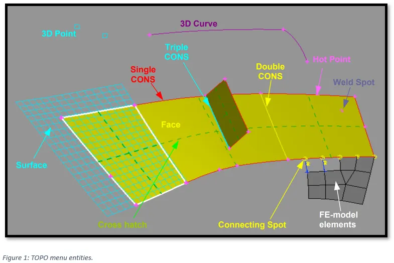
The Surface is the underlying mathematical CAD description of the Face where the actual mesh takes place. The CONS (Curves ON Surfaces) are the boundaries of the Faces. According to their connectivity, they are coloured in Red (single edge), Yellow (double connectivity) or Cyan (triple -or more- connectivity). The Hot Points are the end points of CONS. 3D Curves are curves in space that are used for CAD constructions, but they are not connected to the Faces. 3D Points are also used for geometrical constructions.
Correspondingly, in the MESH and DECK menus:
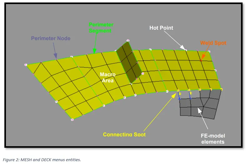
A Macro Area may consist of one or more joined Faces. The Perimeters are the boundaries of the Macro Areas. The Hot Points are the end points of the Perimeters. FE-model mesh is a mesh that is not associated to geometry (dead-mesh). Finally, a yellow Connecting Spot indicates connectivity of a Macro area with FE-model mesh.
Procedure:
1) Importing the CAD model.
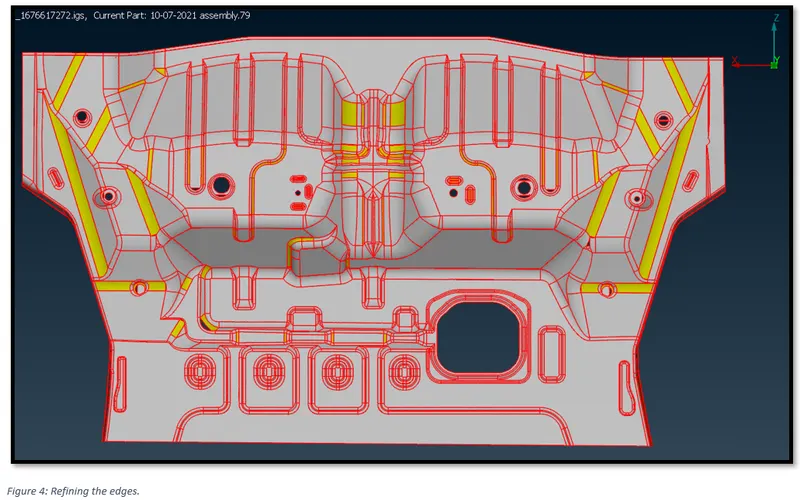
To make the coarse edges smooth, they need to be refined. Go to, Mesh -> Perimeters -> Length -> 0.1.
2) Geometric Clean Up of the CAD Model.
2.1) CONES in the geometry
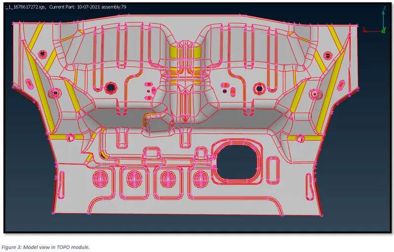
From figure 3, it can be observed that there are Single cones (Red Lines) i.e., edges shared with only single surface.
To establish connectivity between the surfaces, go to, Faces -> Topo, in theTopo module. Select all the surfaces.
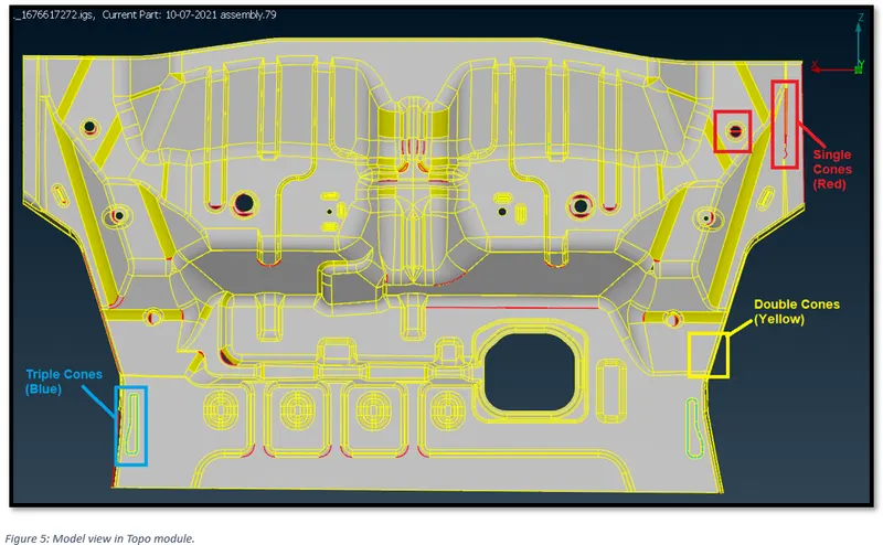
Now, from figure 4, it can be observed that there are, Single cones (Red Lines) i.e., edges shared with only single surface and Double cones (Yellow Lines) i.e., edges shared with two surfaces and Triple cones (Blue Lines) i.e., edges shared with three or more surfaces.
2.2) Checking the Geometry.
To identify and isolate on the screen the problematic areas that require the user’s attention, checks manager is used.
In the toolbar on the top of the screen, go to, Checks -> Geometry.
This will open ‘Checks Manager’ window.
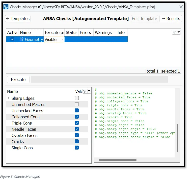
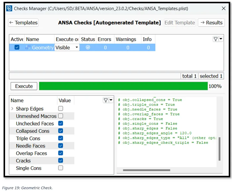
Here we can select the type of problems that may exist in the geometry of the model to be investigated by activating the corresponding flag in the lower part of the window. Keep the default options and click Execute.
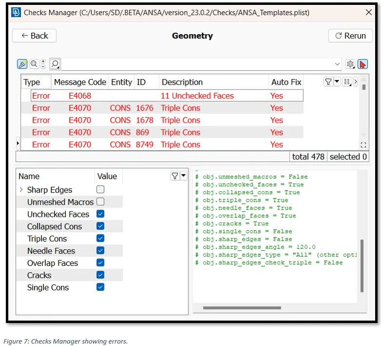
ANSA identifies a total of 478 errors in the geometry of the model.
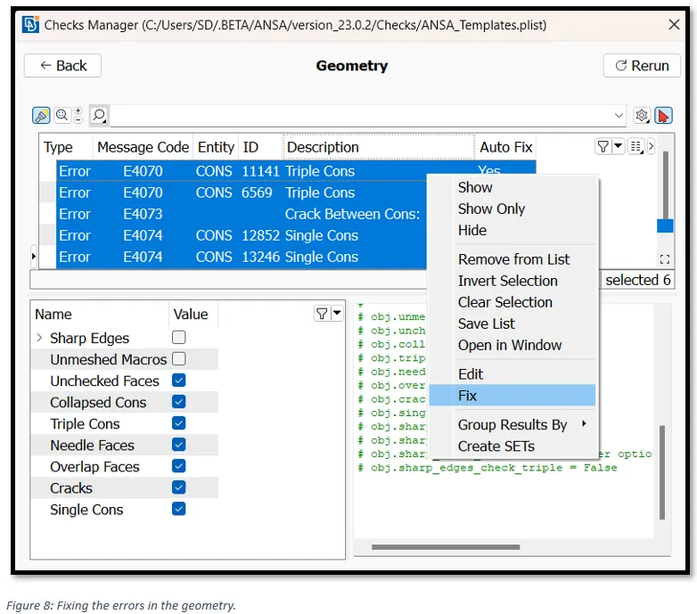
To auto fix the errors select all the errors, right click and click on fix. This will resolve some of the errors.
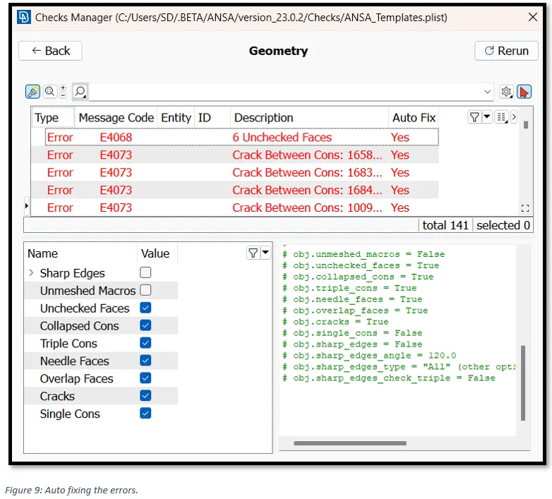
Even after auto Fix, we can see 141 errors are remaining that ANSA could not resolve. This error needs to be resolved manually.
Some of the geometrical error along with manual fix are as shown below.
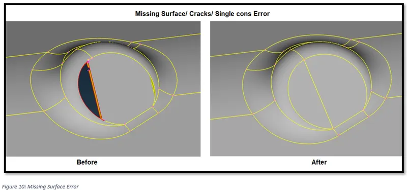
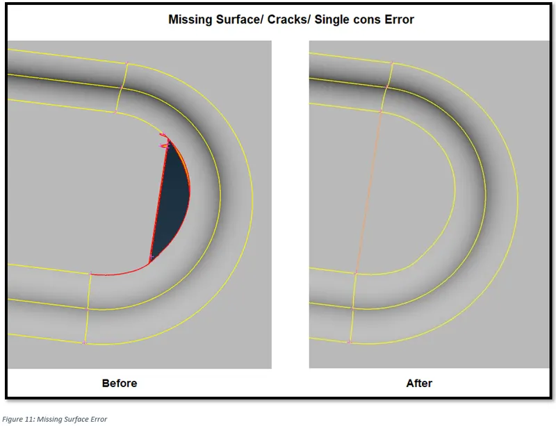
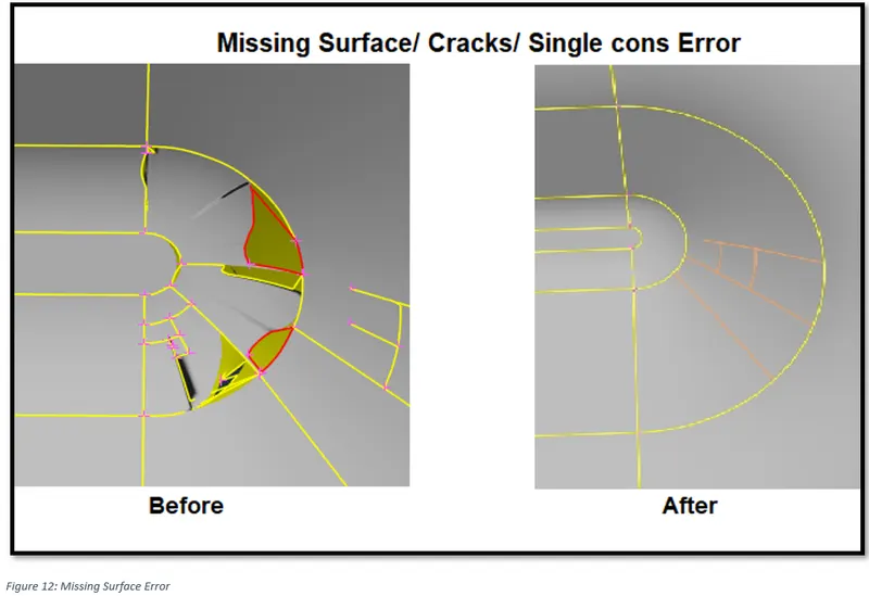
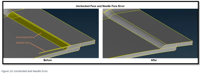
Errors shown in above figures can be resolved by deleting and recreating new faces by using “fill hole” option or by creating new face.
To do this go to,
Topo module -> CONS -> Fill Hole
Topo module -> Faces -> New
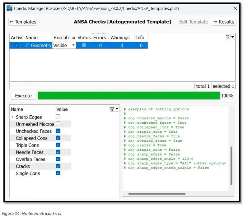
Now, again running the geometric check we can see that the errors are resolved.
3) Extracting Mid Surface.
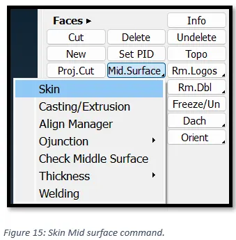
To Extract the mid-surface of the Model, we would use ‘Skin mid-surface’ command. Go to, Faces -> Mid Surface -> Skin.
In the “option list” at the bottom, change the “Skin Property” to “Ask always”. This will help in creating a new property card of the model component one by one. And we can simultaneously put the thickness of the model in the new property card.
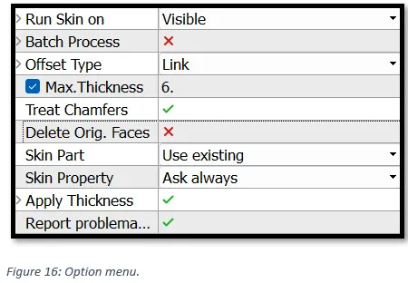
Select the model and press enter.
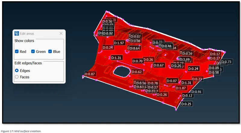
It will prompt us to identify the red, blue and green surfaces. Select outer face as green, inner face as red and face in between as blue.
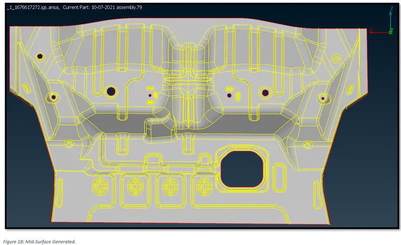
Finally, we can see the mid-surface of the entire component in Figure 18.
4) Geometric Clean Up of the Mid-Surface.
Now, again checking the problematic areas in the geometry using Checks manager. As shown in Figure: 19, there is no geometrical issue (Needle face).
5) Assigning mesh element length.
In the Mesh menu, go to, Perimeters -> Length -> Box select the model -> set Perimeter length as 5.
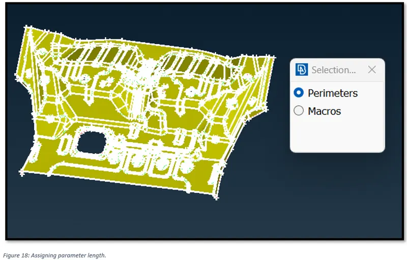
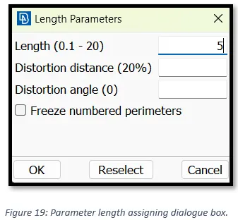
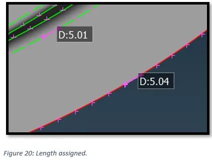
Inspecting the model area by area, to check if the perimeter length is matching our mesh length requirement.
6) Setting up Quality Criterion.
In order to avoid deviation from the quality after meshing, we need set up quality ranges. In Utilities tab, select ‘Quality criterion’.
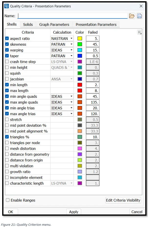
Setting up mesh parameters. In Utilities tab, select ‘Mesh parameters.
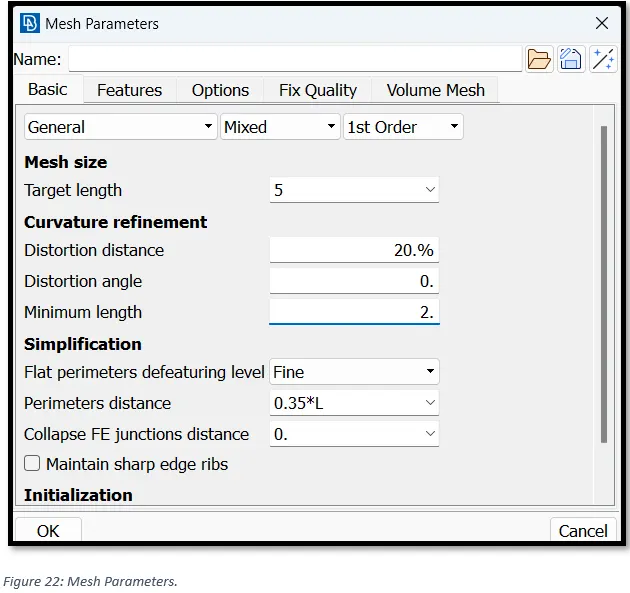
7) Meshing
To mesh the Model area by area, switch to the mesh module, then go to,
Mesh Generation -> Best. In the ‘Feature section, select “Macro Area”.
Now one by one click on the areas to mesh.
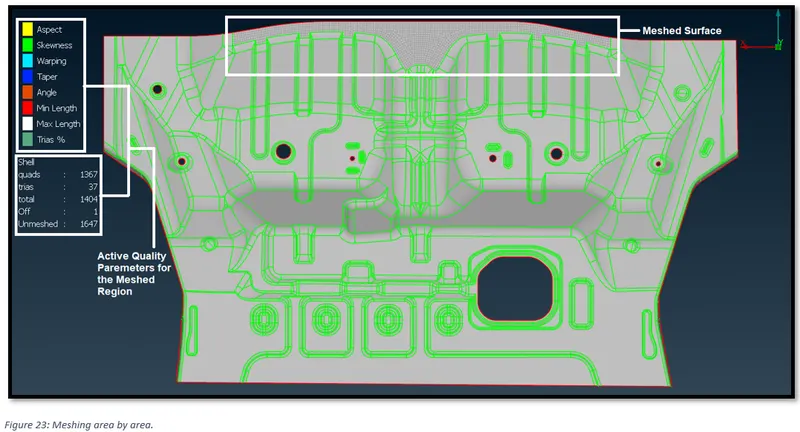
Following rules for should be kept in mind to obtain a good mesh:
- Features should be captured properly.
- Proper Tria Management, i.e., Tria should no touch each other, There should be no opposite trias, Trias near edges and free edges should be avoided.
- Proper Mesh Flow.
- Check if there is any dysconnectivity in the mesh.
- Quality Criteria should be satisfied.
8) Ensuring Quality criteria and Mesh flow.
In some areas we may encounter that the feature lines are very close to each other. Since our min length quality criteria is 2, elements forming in between feature line separated by a distance less than 2 will fail. To avoid this, we may suppress one of the feature lines, keeping in mind making sure there is no major change in the geometry.
To suppress the feature lines, Activate, Mesh -> Macros -> cut -> Right click a feature line to supress.
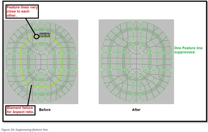
To keep the mesh flow, we can always rearrange the mesh by using:
“Reconstruct” command from the mesh module.
“Split” or “Collapse” command or the combination of both to join two opposite trias or drag the trias to the edge to eliminate it.
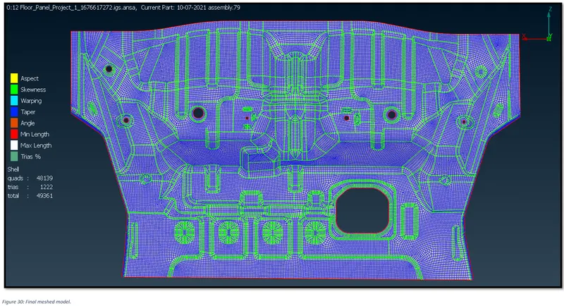
The final meshed model is as shown below:
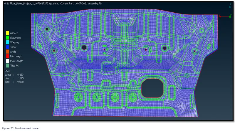
9) Assigning thickness.
Thickness of the model is 1 unit. It can be measured using “Measure” tool.
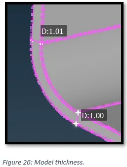
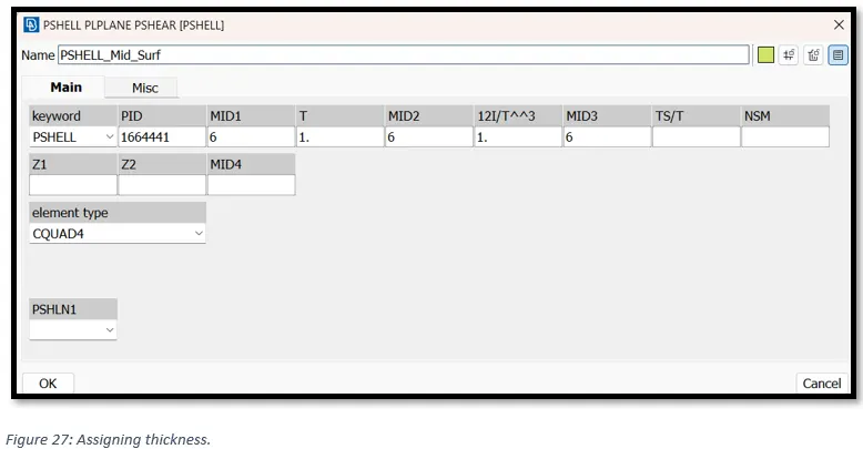
To assign thickness, put T = 1 in the property card.
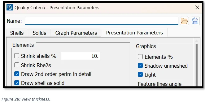
Now, to view the thickness, go to, -> Quality criteria -> Presentation parameters -> check ‘Draw shell as solid’.
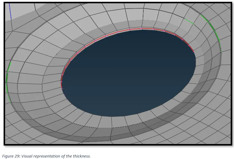
After ensuring no elemental failure as per our quality criteria, the final mesh is as shown below.