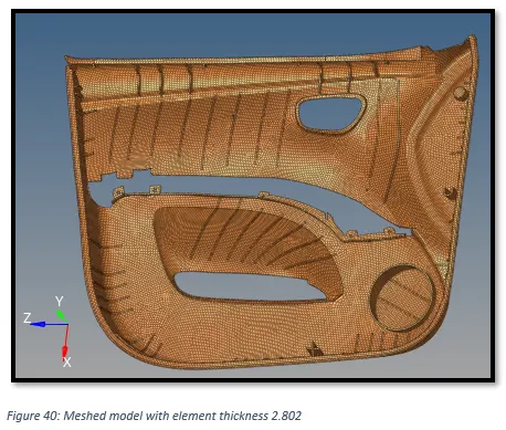
Meshing of Door Inner Panel Challenge
Objective:
- To extract the mid surface of ‘Side door model”.
- To mesh the "Side door model” as per given quality criteria.
Target Element Length = 4 Units
|
S.No. |
Quality Criteria |
Value |
|
1 |
Aspect Ratio |
5 |
|
2 |
Skewness |
45 |
|
3 |
Warping |
15 |
|
4 |
Taper |
0.5 |
|
5 |
Min. Length |
2 Units |
|
6 |
Max. Length |
6 Units |
|
7 |
Min angle Quad |
45 |
|
8 |
Max angle Quad |
135 |
|
9 |
Min angle Tria |
20 |
|
10 |
Max angle Tria |
120 |
|
10 |
Tria % |
10 |
- Assign the thickness to the meshed model.
Introduction:
In the project we are required to mesh a ‘Side door’. Firstly, we will extract the mid surface of the ‘Side door’. Secondly, we will 2D mesh the mid surface as per the given quality criteria. Finally, we will assign the thickness to the mesh.
In general, 2D meshing is used for parts having a width / thickness ratio > 20. And we extract mid surface because it represents the geometry appropriately and makes 2D meshing continent. But for a geometry of variable thickness, 2D meshing would lead to higher approximation.
Steps taken:
1) Analysing the ‘Side door’ model.
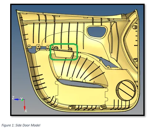
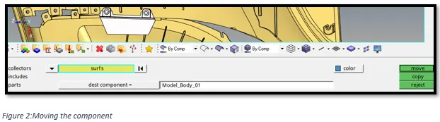
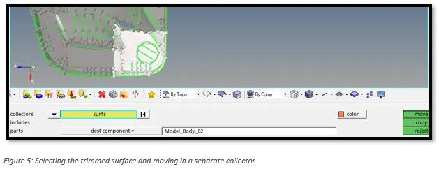
We can see we have two components in one collector. The green encircled part in above figure is not required for meshing, so moving it in a separate collector using ‘Organise’.
Go to, Tools -> organise -> Select the surface and click on move.
We can also be observed the given model is big and have many features and curves. So it would be easy to divide the mode in 4 parts and then mid surface one by one.
Dividing the model in 4 equal parts:
Go to, Geom -> Surface edit (or, shift + f9) -> trim with surfs/plane -> with plane -> then select the axis and base node and click on trim.

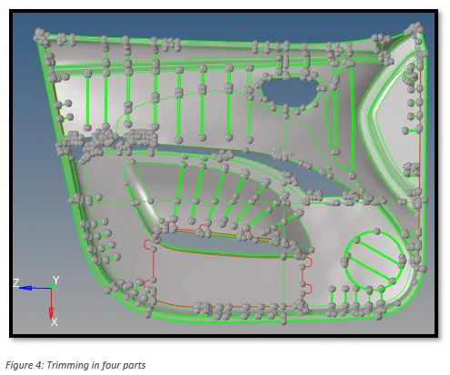
Moving the trimmed section in a separate collector:
Go to, Tools -> Organise -> select the surfaces and move them in separate collector.
2) Extracting the mid surface.
Now we will extract the mid mid-surface of the “side door’ model one segment at a time.
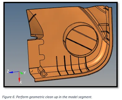
To extract the mid surface of the following segmented model, firstly we need to perform the geometric clean-up i.e. simplifying the geometry by removing small fillets, unwanted feature lines etc. This will aid in extracting the mid-surface easily.
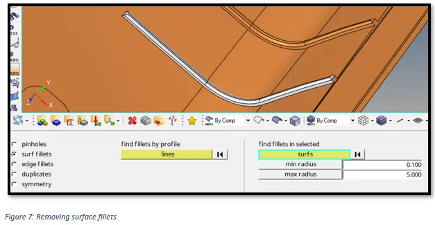
Defeaturing the fillets on the ribs:
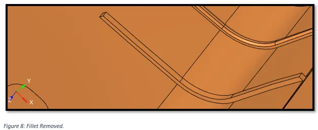
Go to, Geom -> defeature -> surf fillets -> select the fillet surface -> Click on find and then remove.
Now Go to, Geom -> Mid surface -> select the surfaces -> Click on extract
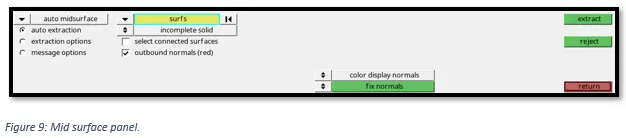
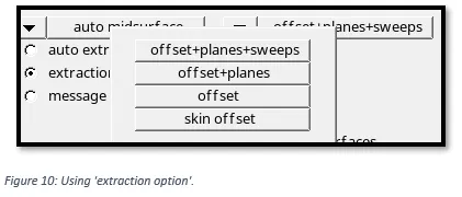
We can also use the ‘extraction option’ within ‘mid surface’ panel to generate the mid surface in four different ways i.e., offset +planes +sweeps, offset +planes, offset and skin offset. Then we can select the best mid surface by organising them in a separate collector.
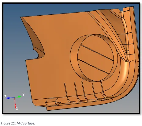
There will be some surfaces whose mid surface might not get extracted. In that case we nee to extract the mid surface manually. We can manually create the mid surface by either creating a 2D surface or by off-setting the surface.
Creating mid surface of the following rib manually,
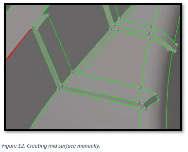
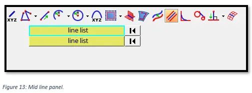
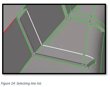
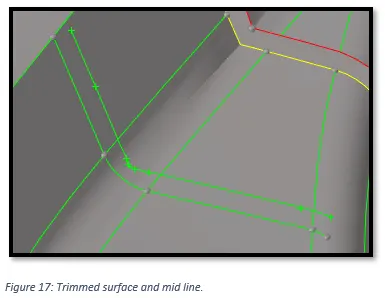
Creating mid line, go to, Geom -> Lines -> Mid line - > select both the of the line list -> click create
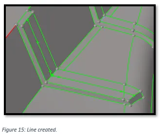
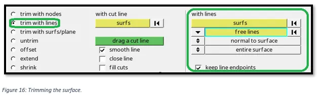
Now, trim the surface using the mid line. Go to, geom -> surface edit -> trim with lines -> select the free line and the surface that you want to trim -> click on trim.
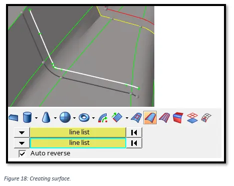
To create the surface, go to, Geom -> Surfaces -> Ruled - > select both the of the line list -> click create.
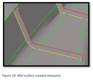
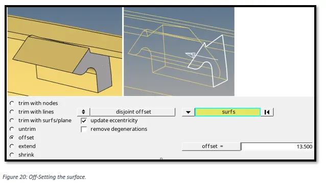
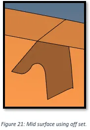
Creating mid surface of the following features manually by off-setting,
Go to, Geom, surface edit -> off set -> select appropriated off set distance -> click on off set.
Mid-surfaces of rest of the model segments are shown below:
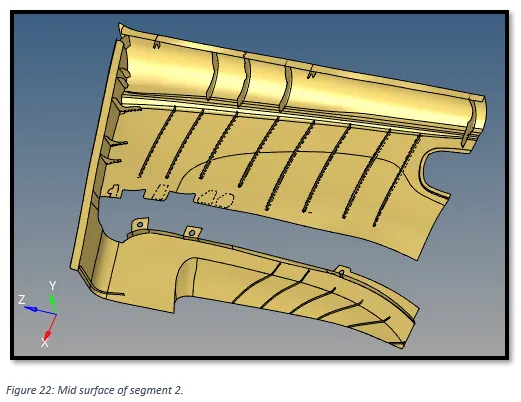
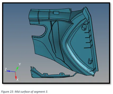
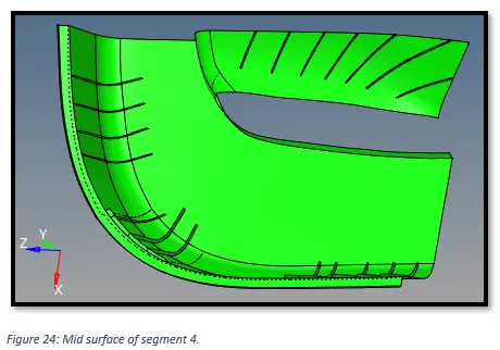
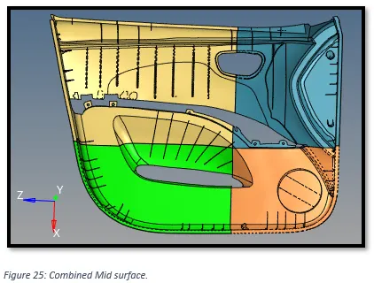
3) Combining all the Mid-Surface segments.
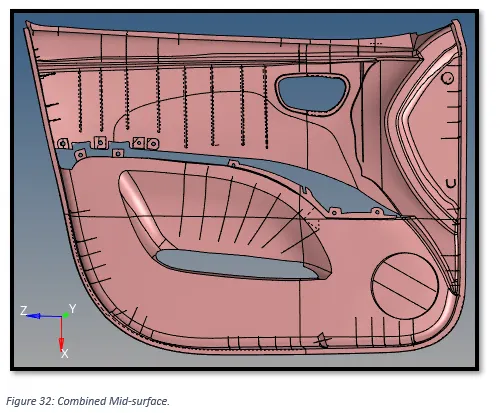
To combine all four segmented mid-surfaces, we have to merge all the free edges.
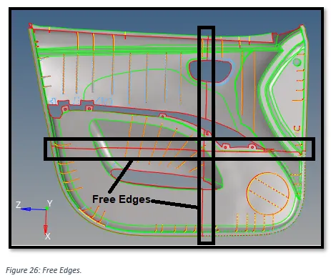
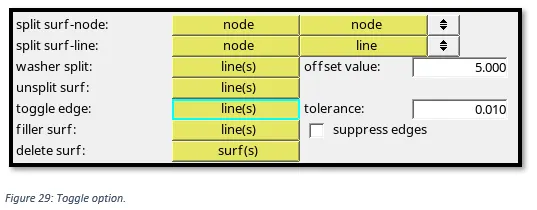
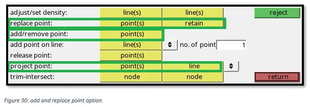
To combine free edges, we can use equivalence, toggle, filler surface to fill any missing surface, or create and replace points option.
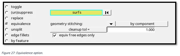
To use equivalence, go to, Geom-> edge edit -> equivalence
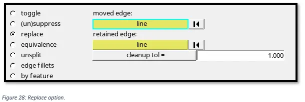
To use replace, go to, Geom-> edge edit -> replace
To use ‘toggle’, go to, Geom -> quick edit -> toggle
To use, ‘add and replace’ points, go to, Geom -> quick edit
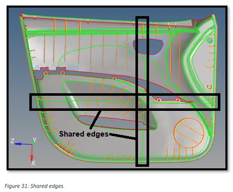
After combining the free edges, the combined surfaces are joined by shared edges (green) as shown below.
4) Meshing the Mid-surface.
Setting up criteria file setting as per given parameters.
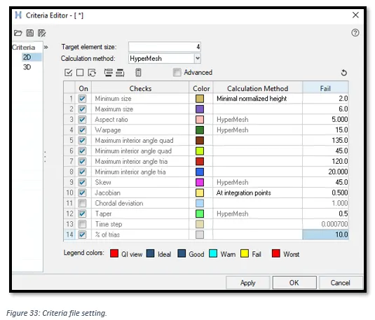
Now, go to, 2D -> Automesh -> select all the displayed surfaces -> click on mesh
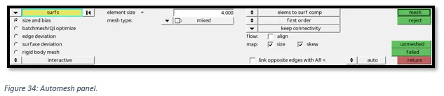
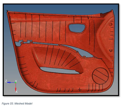
5) Assigning thickness to the Mid-surface.
Under the model tab, right click and go to, Create -> Property.
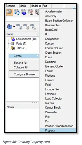
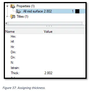
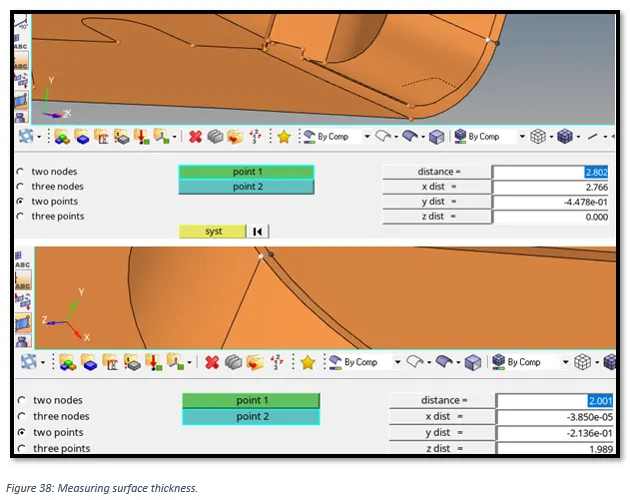
Rename the property card and assign the thickness as per the model thickness. Since the model have a varying thickness, we may either take an average thickness. But for this model we are taking element thickness as 2.802, since majority of surface thickness is 2.802.
To measure surface thickness we can go to, Geom -> distance.
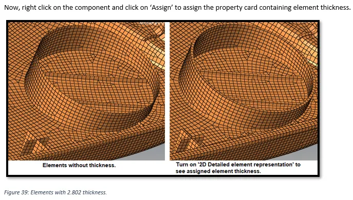
Now, right click on the component and click on ‘Assign’ to assign the property card containing element thickness.
Figure 38: Elements with 2.802 thickness.
Finally, we can see meshed inner door panel model with element thickness 2.802.