Project 1 Mechanical design of battery pack
Mechanical Design of a Battery Pack
Introduction:
One of the fundamental components of an electric powertrain is the battery pack. The battery pack is the energy source for the vehicle, and for high-performance vehicles, it must supply energy to the vehicle at very high power. The automotive environment is especially challenging for batteries, as the batteries are subject to a wide range of operating conditions. Thermal considerations are critical to the safety and performance of battery packs, a challenge that is intensified in cars because of the increased heat generation in batteries at high charge and discharge rates, which are necessary for high power output. Mechanical robustness is also a critical challenge, the battery pack must not only be able to withstand vibration and loads from normal driving conditions and accelerations and decelerations, but also maintain structural integrity in crash scenarios. This is especially important for safety because impacting lithium-ion batteries can be extremely dangerous and cause catastrophic failure of the entire battery pack.
A battery pack is a set of any number of (preferably) identical batteries or individual battery cells. They may be configured in a series, parallel or a mixture of both to deliver the desired voltage, capacity, or power density. The term battery pack is often used in reference to cordless tools, radio-controlled hobby toys, and battery electric vehicles.
Components of the battery pack:
- Cells (Different form factors & chemistry types)
- BMS (Electronics to manage the battery)
- Connection System (Connector, pigtail, wires)
- Housing (Plastic, sheet metal, shrink, etc.)
Cells:
- A pack can contain one cell or many cells configured to achieve higher capacity or output voltage.
- The cell is considered the “fuel tank” of the battery pack system, holding the energy that will be released during discharge (when the engine is running) or replaced during a charge cycle (when the tank is refilled at a gas station).
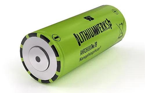
fig. Single Cell
BMS:
- The BMS is an electronic system that manages a rechargeable battery to ensure it operates safely and efficiently.
- It is designed to monitor the parameters associated with the battery packs and their individual cells, apply the collected data to eliminate safety risks and optimise the battery performance.
fig. Circuit for Battery Management System
Connection System:
- The connection system is what transforms a cell into a battery pack.
- There must be a connection between the cell and the BMS in order to interface with each other.
- Nickel strips are the preferred method of connecting a battery cell to the control system. A thin strip of nickel is capable of carrying high amounts of current, is flexible, durable, and can be attached to the cell without the use of excessive heat.
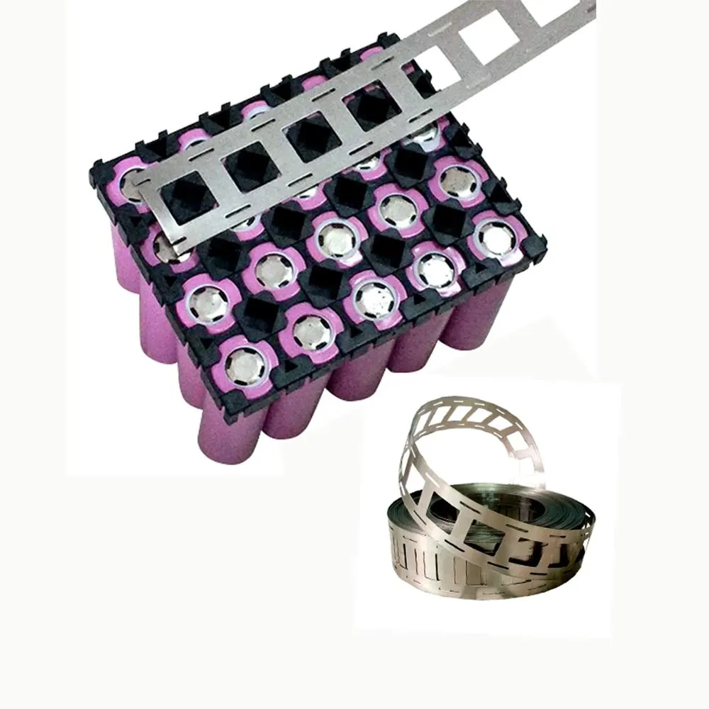
fig. Nickle strips with spot welding on the battery pack
Housing:
- All these components need to be packaged so that the battery pack can be installed into a device.
- Once all components are properly placed and connected to one another, they are sealed with either shrink wrap or a hard case.
- The housing ensures that the components remain safely located and provides a clean package for eventual use by an end-user.
- The type of housing depends on where the battery pack will be located inside the device and if it is intended to be accessed by the end-user or a technician.
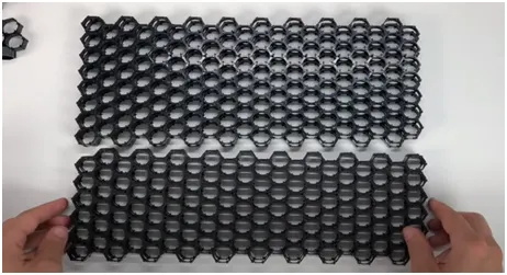
fig. Hexagonal Housing cases for cell connection
Thermal management:
- Thermal management is a major issue in high power designs, particularly for automotive applications.
- As part of the battery system, it may be necessary to provide air or water cooling ducts, pumps or fans and heat exchangers for high temperature working or heaters for operating in low-temperature environments.
- The layout of the cells should be conducive to managing heat flows within the pack.
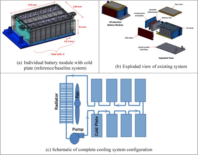
fig. Thermal Management of the Battery Pack
Complete battery pack:
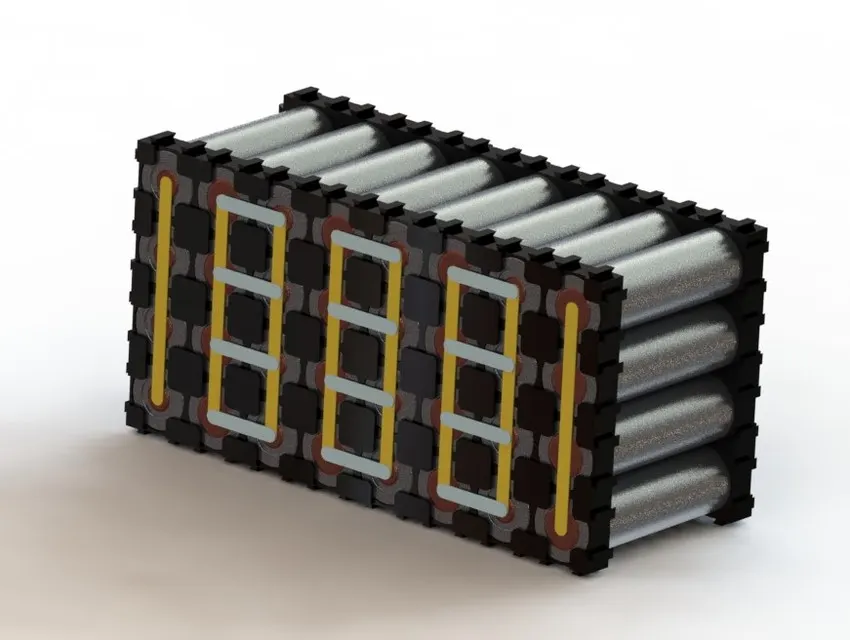
fig. Cell connected in Series & Parallel arrangement to form a Battery Pack
Steps followed in battery pack construction:
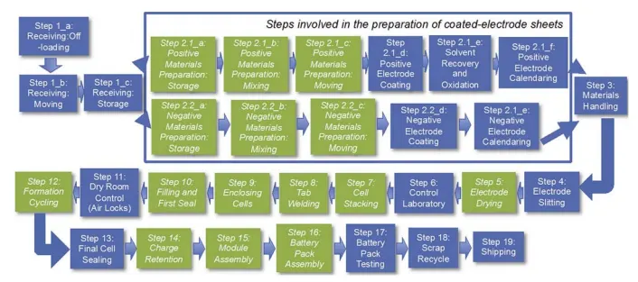
fig. Battery Pack construction process chart
Enclosure Design:
- Whilst the energy density improvements of Li-ion cells might be the most prominent battery improvements in the public eye, we are also seeing an increase in pack-level energy density at a greater rate than just cell-level improvements.
- Manufacturers are improving their battery designs, the mass of materials being used around the cells is steadily being reduced, allowing for a lighter battery pack or more cells to be used for the same mass.
- The choice of materials for several pack components also affects these improvements. More interest is being paid to composite enclosures for light-weighting, fire-retardant materials, thermal interface materials and much more.
- The thermal management strategy also impacts these choices, with increased energy density and consumer demand for fast charging, the thermal management must be more effective but also present a smaller and lighter package.
- Battery pack materials forecasted include aluminium, copper, thermal management materials, thermal interface materials, steel, glass fibre reinforced polymers, carbon fibre reinforced polymers, inter-cell insulation, compression foams and housings and pack fire-retardant materials.
- Enclosures made from injection moulded plastics are most commonly used for battery packs. For these enclosed pack designs, two or more plastic parts are moulded and then assembled with the pack and accompanying circuitry. They can be sealed using glue, mechanical fasteners (Screws) or ultrasonic welding. The product cost can be reduced by using insert mouldings in which the interconnection strips and the terminals are moulded into the plastic parts to eliminate both materials and assembly costs.
fig. Audi eTron SUV Battery pack enclosure
Calculating mechanical design parameters for the battery pack of 18`kWh`:
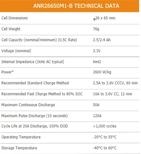
(1) Cell specifications: ANR26650M1-B :
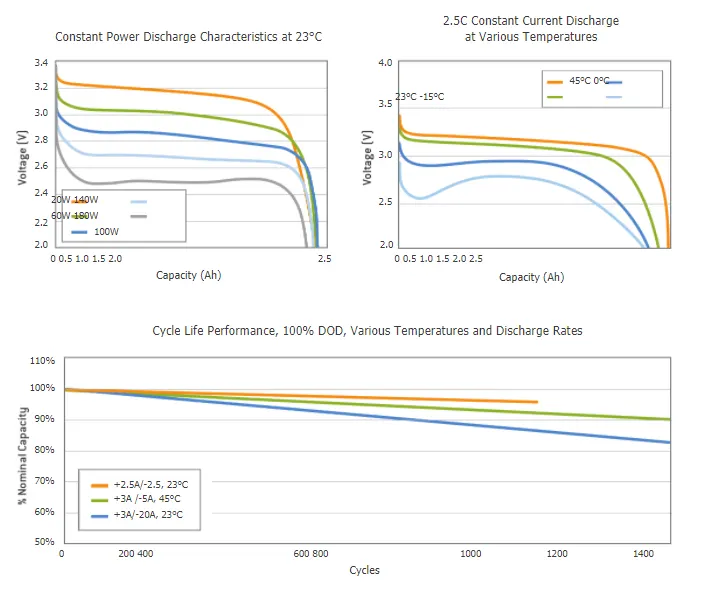
(2) The plot of cell behaviour:
(3) Cell dimensions:
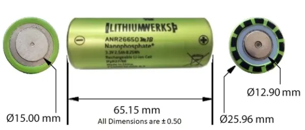
(4) Cell calculation:
Cell volume `V_c`= `pi*r^2*h`
= `pi * (0.013)^2 * 0.065`
= 0.0000345
| `V_c = 3.45*10^(-5) m^3` |
Cell energy = Nominal voltage * Nominal cell capacity
= 3.3*2.5
= 8.25
| `E_c` = 8.25 `Wh` |
Cell energy density = cell energy/cell volume
=`8.25/0.0003`
= 24.3
| `U_c`= 24.3 `(kWh)/(m^3)` |
(5) Battery pack assumptions:
- A Battery voltage is 240V.
- All cells will be of ANR26650M1-B type.
(6) Battery pack calculations:
Total number of cells = `S_c * P_c`
`S_c`= Number of cells in series
`P_c` = Number of cells in parallel
`S_c= V_b/V_c`
= 240/3.3 = 72.72
| `S_c` = 73 cells |
`P_c = C_b/C_c`
`C_b` = Battery pack capacity = 18kW (given)
`C_b` = Energy/Battery Voltage
= 18000/240 = 75
| `C_b` = 75 `Ah` |
`P_c` = 75/2.5 = 30
| `P_c`= 30 cells |
Therefore, `C_t` = 73 x 30 = 2190
| `C_t` = 2190 cells |
| The Battery pack is 73S30P |
Total cell Volume = Cell volume * Total number of cells
= `V_c * C_t`
= 0.000034 * 2190 = 0.0744
| Total cell Volume = 0.0744 `m^3` |
Energy density = Battery pack energy/Volume
= 18/0.0744 = 241.74
| Energy Density = 241.74 `(kWh)/(m^3)` |
Weight = Total number of cells * Cell weight
= 2190*76
= 166440 grams
| Weight of the Battery pack = 165 kg |
Mechanical Design of Battery Pack:
Reference:
- https://datasheetspdf.com/pdf/1424845/A123Systems/ANR26650M1-B/1
- https://www.youtube.com/watch?v=VHoKwqzLh-A
- https://x-engineer.org/automotive-engineering/vehicle/electric-vehicles/ev-design-battery-calculation/
- https://www.idtechex.com/en/research-report/materials-for-electric-vehicle-battery-cells-and-packs-2021-2031/796
- https://www.epectec.com/batteries/battery-enclosure-design.html