Mechanical design of battery pack
Battery packs form the core of electric vehicle technology. Batteries with high energy density, high power density, and long cycle life are needed to support the faster introduction and smooth integration of electric vehicles. Battery pack, consists of series of individual modules conned with each other along with protection. A module, is a group of cells connected in series or parallel based on the requirement. A cell, is a single unit device which converts chemical energy into electrical energy and vice versa.
The high voltage battery pack is one of the most important components of any electric vehicle . The traction battery of an electric vehicle must achieve the following thing :
- Provide maximum traction motor torque
- Vehicle range in sense of kilometre
- To achieve the proper life cycle of battery
A battery cell consists of five major components: electrodes – anode and cathode, separators, terminals, electrolytes, and a case or enclosure. For automotive applications, there are different types of cells used Individual battery cells are grouped into a single mechanical and electrical unit called a battery module. The modules are electrically connected to form a battery pack.
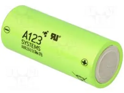
In our project, we are considering one of such kind of cell ANR26650M1-B. This cell is manufactured by A123 having high-performance Nanophosphate lithium iron phosphate (LiFePO4) battery technology delivers high power and energy density combined with excellent safety performance and extensive life cycling in a lighter weight, more compact package.
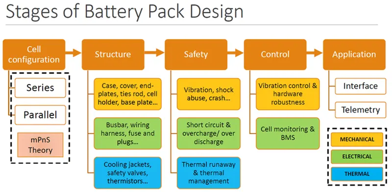
There are various factors that determine the power supply of an EV motor. They are essentially divided into four categories: voltage, electrical capacity, characteristics, and safety. Lithium-ion batteries are the mainstream battery cells for EVs, although they only provide 3.6 V per cell. Normally, a 7.2 V cell is used as one module, and four modules are connected in series and parallel. Depending on the manufacturer, these modules are connected in series and used to provide voltages such as 280 V or 360 V.
The second category is the electrical capacity. This is important because the cruising distance will increase if the electrical capacity is high.
Third, lithium-ion batteries have specific electrical characteristics based on temperature. The temperature rises due to charge and discharge, and the output voltage decreases when the temperature exceeds 70 ℃. Moreover, the internal resistance increases when the temperature falls below -30 ℃.
Finally, there are also safety concerns. Liquid leakage may occur due to the use of electrolytes. Precautionary measures against leaks in the module are critical to prevent problems while driving.
The cell considered for the project is ANR26650M1-B which is a LiFePO4 cell also known as LFP, LFP is a popular, cost-effective cathode material for lithium-ion cells that are known to deliver excellent safety and long life span, which makes it particularly well-suited for specialty battery applications requiring high load currents and endurance. Lithium Iron Phosphate has LiFePO4 as the cathode and graphite as the anode.
Anode reaction: LiC6 <---> C6 + Li+ + e-
Cathode reaction: FePO4+ Li+ + e- <---> LiFePO4
Overall reaction: LiFePO4 + C6 <---> LiC6 + FePO4
Phosphate is used as a cathode in lithium iron phosphate batteries, often known as li-phosphate batteries. They have low resistance qualities, which improve their thermal stability and safety. fully charged batteries can be kept with no effect on the battery’s overall charge life. When the lengthy battery life of Li-phosphate batteries is considered, they are frequently the most cost-effective option. The lower voltage of the lithium-phosphate battery, on the other hand, means that it has less energy than other lithium batteries. As a result, these batteries are frequently used in electric bikes and other applications requiring a long lifecycle and high levels of safety. These batteries are also commonly used in electric vehicles.
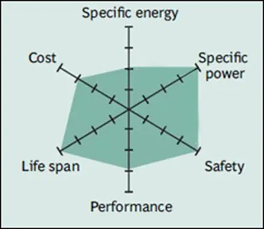
Li-phosphate has excellent safety and long life span but moderate specific energy and elevated self-discharge. Li-phosphate is more tolerant to full charge conditions and is less stressed than other lithium-ion systems if kept at high voltage for a prolonged time.
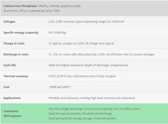
We can see in the later stages of this project that we get the specific energy within the range specified in the above image.
Characteristics of ANR26650
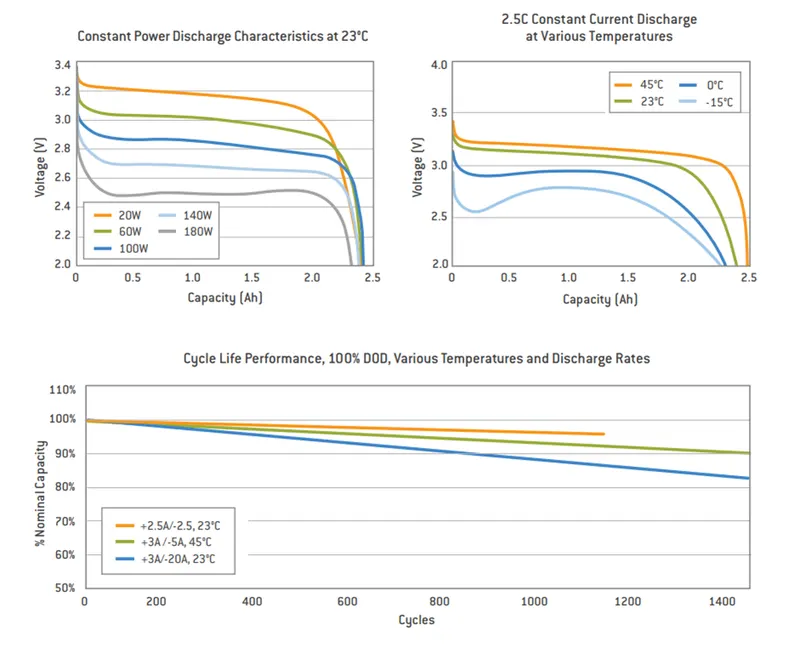
In the above figure the first plot shows, for constant temperature and varying capacity and the second one for, constant capacity and varying temperature and the last one for, capacity changing for different c rate and temperatures.
The cell specification required for our project is mentioned below.
Cell Dimensions: Diameter 26mm, height 65mm.
Cell weight: 76 g.
Nominal Cell capacity: 2.5 Ah
Nominal Voltage: 3.3V
Here in our project, we are assuming that the Voltage as 360V and power as 18kW.
Voltage = 360V
Since we have power and voltage, we can determine the pack current,
Power = voltage*current
Current = Power/voltage = 18000/360 = 50 A
Current capacity = 50 Ah
Since we know the current capacity, the number of cells in parallel connections can be determined.
The cells which are connected in parallel have same voltage and the capacity get added up, so in order to get higher capacity it is better to connect more number of cells in parallel connections.
In our project, the total number of cells connected in parallel can be determined by,
No. of cells in parallel connections = Total pack current capacity/Nominal cell capacity = 50/2.5 = 20 cells.
There are 20 number of cells connected in parallel connection.
A battery pack has a configuration of xSyP where x is number of cells in series and y is number of cells in parallel.
Till now we have determined number of parallel cells, number of cells in series can be determined by the assumed voltage. As the capacity gets added up in parallel connection the current in series connection remains constant whereas the voltage gets added up by this we can determine the number of cells in series connection.
No of cells in series connection = Total voltage / Nominal cell voltage = 360 / 3.3 = 109.09~ 110 cells.
There are 110 cells in series connection the number of cell is rounded off to the whole number from the decimal number.
Now we can say that the configuration of our battery pack is 110S20P which means there are 110 cells in series and 20 cells in parallel connection.
Pack configuration: 110S20P
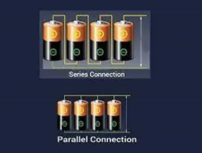
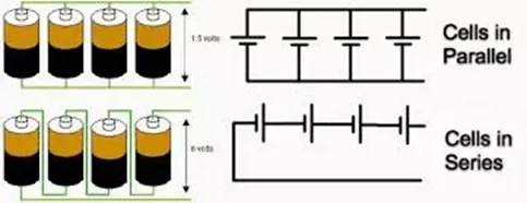
We have more number of cells in series connections as we need the motor to operate at higher voltages, reason being, A higher voltage system allows a lower current to be used when charging the battery, which reduces overheating and allows better power retention in the system. This power can be used towards a longer driving range.
Now that we have the pack configuration we can determine the total number of cells in our pack,
Total number of cells = No. of cells in series*No. of cells in parallel = 110*20 = 2200 cells.
Total cells in pack: 2200 cells.
Now that we have got the number of cells involved in the battery pack construction we can determine the pack dimensions.
Let us consider, the number of cells connected in series along the length of the battery pack for simple model,
By this assumption we get the length of our battery pack as,
Here we are assuming the gap between cells as 4mm so in order to get this gap we are adding 4mm to the cell diameter 2mm on either sides.
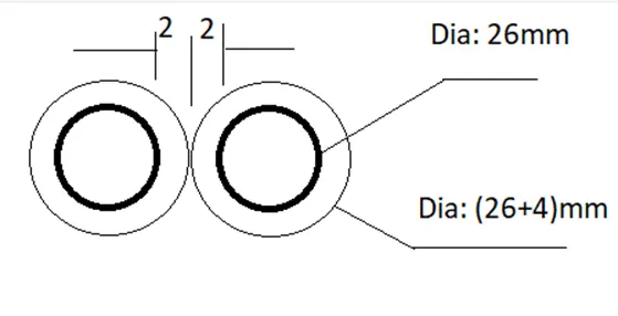
Length of battery pack = No. of cells in series connection * (diameter of single cell+ cell spacing)
= 110 * (26+4) = 3300mm
Length of battery pack = 3.3 meters.
Similarly for width, we are assuming the parallel connection along the width of our pack again to keep the design simple.
Width of battery pack = No. of cells in parallel * (diameter of single cell+ cell spacing)
= 20 * (26+4) = 600mm
Width of battery pack = 0.6 meters.
Now that we have length and breadth we need height of the pack, which can be determined by adding the height of cell with the other parameters such as cell holder, metal strips and some space for wiring and cooling functions, we will assume approximately 35mm for all this parameters. So now the height of battery pack is,
Height of battery pack = (Height of individual cell + 35) = 65+35 = 100mm.
So now that we have got the length, breadth and height, the area and volume can be determined.
Since we are assuming that our battery pack is in rectangular shape,
Area of battery pack = Length of battery pack * Width of battery pack
= 3.3*0.6 = 1.98 m2.
Area of battery pack = 1.98 m2.
Volume of battery pack = Area of battery pack * height of battery pack
= 1.98 * 0.1 = 0.198 m3.
Volume of battery pack = 0.198 m3.
For weight of battery pack, (we are considering only the weight of cell and ignoring the holder, metal strips and cover weight)
Weight of battery pack = weight of individual cell * number of cells
= 76 * 2200 /1000 = 167.2 Kg
Weight of battery pack = 167.2 kg
Now that we have determined the volume and area of battery pack,
Specific Energy = overall energy of battery pack / Weight of battery pack
= 18000 / 167.2 = 0.1076 kWh/kg
Specific Energy = 0.1076 kWh/kg
Energy Density = overall energy of battery pack / Volume of battery pack
= 18000 / 0.198 = 90.90 kWh/m3 or 0.0909 kWh/lt
Energy Density = 0.0909 kWh/lt
The arrangement of our battery pack will look like the image shown below,
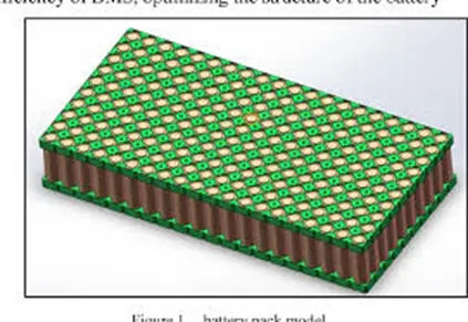
Which is of the rectangular form similar as our case, once the number of cells required and other parameters are calculated voltage of these cells connected in series, so that all the voltages of the cells lie in the specified range. Also, the batch of the cell is verified. This is to ensure that there is no any mismatch in the configurations of cells.
Placing the cells in cell holder,
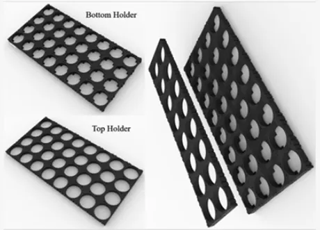
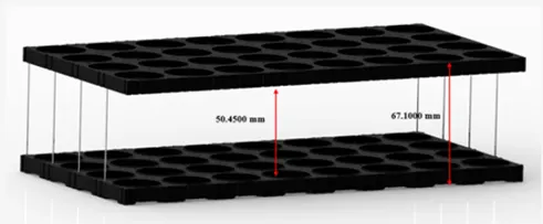
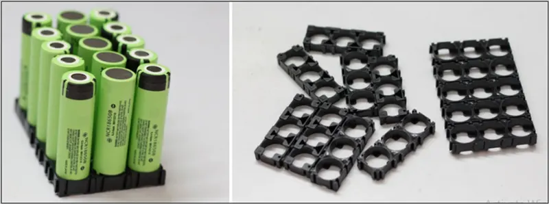
The above images shows the type of holders used to place the cells in order, the dimension of the holder base will be approximately same as the length and width calculated with the cells, but will have some clearance in addition. The cells are then arranged as per the configuration required.
Once the cells are placed as per the requitement the nickel stripes are placed on the faces of cells. The function of Nickel strip is to connect these cells with each other
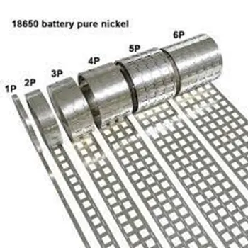
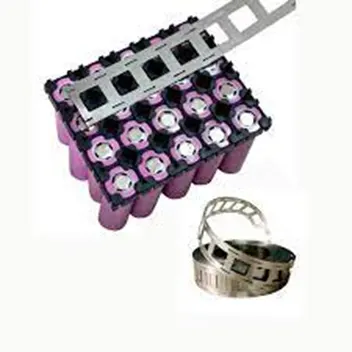
There are two options to connect these cells together: 1. Soldering 2. Spot Welding
Soldering
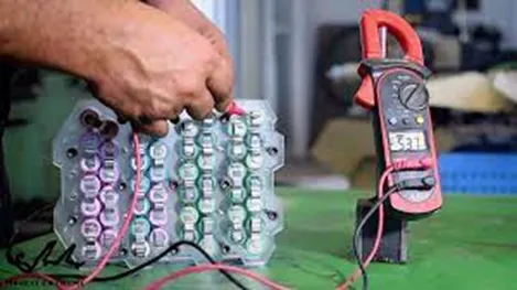
Soldering is a joining process used to join different types of metals together by melting solder. Solder is a metal alloy usually made of tin and lead which is melted using a hot iron. The iron is heated to temperatures above 600 degrees Fahrenheit which then cools to create a strong electrical bond. However, soldering is the more cost effective way when compared with spot welding.
Spot welding
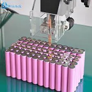
The principle of spot welding is to employ heat to connect the metal surfaces. The heat is generated from metal resistance to the electric current supplied. A spot-welded connection is much smaller than a soldered connection. It’s also important to consider that a spot weld is something that essentially happens on a 2d plane. A solder joint, on the other hand, is a large structure that extends off the surface of the plane it is being soldered to. This makes a soldered connection physically stronger, but again, this extra strength is not needed and comes at the cost of several other key performance metrics. Welded connections are plenty robust enough for building battery packs and their nature makes them ideal for compact battery construction.
Once the connection between the cells is well established by spot welding or soldering, the excess strip are removed. Then the BMS is connected.
Battery Management System,
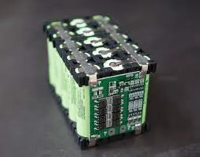
The Battery Management System is a system that is used to predict the health and capacity of the charge in the battery. It is an electronic control circuit that monitors and regulates the charging and discharging of batteries. It is also used to determine the SOC and state of health of the battery. The main use of the BMS is the safety purpose to not reaching over currents and voltage and also the temperature.
The BMS not only monitors the values but also for the detection of battery type, voltages, temperature, capacity, state of charge, power consumption, remaining operating time, charging cycles, and some more characteristics.
The oversight that a BMS provides usually includes:
- Monitoring the battery
- Providing battery protection
- Estimating the battery’s operational state
- Continually optimizing battery performance
- Reporting operational status to external devices
Features of BMS,
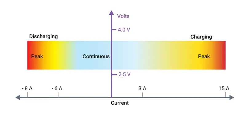
Electrical Management Protection: current and voltage.
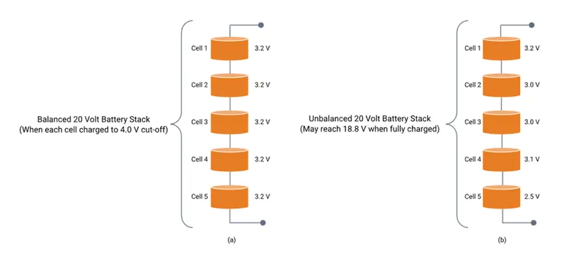
Capacity Management. Maximizing a battery pack capacity is arguably one of the most vital battery performance features that a BMS provides. This capacity management can be done by two kind of cell balancing, active and passive.
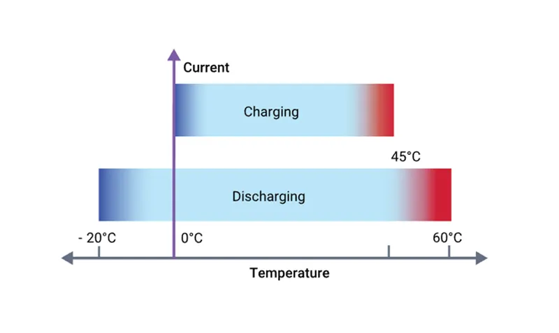
Thermal Management Protection: Temperature. A BMS can control the temperature of the battery pack through heating and cooling.
The thermal management can be done in two ways passive and active cooling.
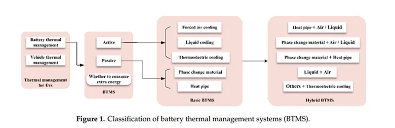
For our project we can use forced air cooling as we have gaps between the cells in our arrangement.
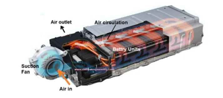
As shown in the above image the air circulates through the pack and removes the heat generated in the same image we can also see the battery enclosure which covers the battery pack from environmental factors.
Conclusion:
A battery pack of 18kWh is created and its specifications are as follows,
Cell Dimensions: Diameter 26mm, height 65mm
Cell weight: 76 g
Nominal Cell capacity: 2.5 Ah
Nominal Voltage: 3.3V
Pack Voltage = 360V
Pack Current = 50A
Cells in parallel = 20 cells
Cells in series = 110 cells
configuration = 110S20P
Total number of cells = 2200 cells
Length of battery pack = 3.3 m
Width of battery pack = 0.6 m
Height of battery pack = 0.1 m
Area of battery pack = 1.98 m2
Volume of battery pack = 0.198 m3
Weight of battery pack = 16702 kg
Specific Energy = 0.1076 kWh/kg
Energy Density = 0.0909 kWh/lt
However, instead of having the configuration as 110S20P the cells can be arranged into modules and further can be connected together as per the space constraint.
References:
https://www.batteryspace.com/prod-specs/6610.pdf
https://www.matsusada.com/column/ev-power.html
https://batteryuniversity.com/article/bu-302-series-and-parallel-battery-configurations
https://www.acc-emotion.com/stories/battery-cell-module-or-pack-whats-difference-infographics
https://www.sciencedirect.com/science/article/pii/S2666330920300157
https://www.samsungsdi.com/column/all/detail/54344.html
https://cellsaviors.com/blog/soldering-vs-spot-welding-lithium
https://batteryuniversity.com/article/bu-105-battery-definitions-and-what-they-mean
https://batteryuniversity.com/article/bu-205-types-of-lithium-ion