Project 1 Mechanical design of battery pack
Aim: To develop a battery pack of 18KW using ANR26650M1-B cells along with the mechanical design.
Objective:
- Data collection from the Nanophosphate High Power Lithium-Ion Cell PDF for Cell: ANR26650M1-B.
- Performing a complete electrical analysis on an 18 kWh battery pack.
- Calculating the battery pack's physical size.
- Take into account the ideal container for the Battery Pack's measurements that we computed.
Solution:
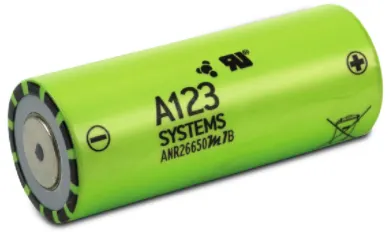
Nanophosphate High Power Lithium Ion Cell ANR26650M1-B
|
Cell Dimensions
|
26 x 65 mm
|
|
Cell Weight
|
76 g |
|
Cell Capacity (nominal/minimum) (0.5C Rate)
|
2.5/2.4 Ah
|
|
Voltage (nominal)
|
3.3 V |
|
Internal Impedance (1kHz AC typical)
|
6mΩ
|
| Power |
2600 W/kg
|
|
Recommended Standard Charge Method
|
2.5A to 3.6V CCCV, 60 min
|
|
Recommended Fast Charge Method to 80% SOC
|
10A to 3.6V CC, 12 min
|
|
Maximum Continuous Discharge
|
50 A |
|
Maximum Pulse Discharge (10 seconds)
|
120 A |
|
Cycle Life at 20A Discharge, 100% DOD
|
>1,000 cycles
|
|
Operating Temperature
|
-30°C to 55°C
|
| Storage Temperature |
-40°C to 60°C
|
EV design - Battery calculation:
Assumptions:
Battery energy = 18 kWh
Voltage (to run the vehicle) = 400V
Calculation:
Energy = 18 kWh
Number of cells (N) = energy / (nominal voltage*capacity)
N = 18000 / (3.3*2.5)
N = 2182
- To generate 18 kWh of energy, we require at least 2182 cells; hence, we must choose between series and parallel configurations.
- The capacity remains the same in a series design, and the voltage equals the total of each cell's voltage.
- The voltage stays the same while capacity increases in a parallel setup.
- We presumptively needed 400 volts to power the car.
- One cell has a nominal voltage of 3.3 V.
Number of series cells required to produce 400 V (Ns) = voltage required / nominal voltage of one cell
Ns= 400 / 3.3
Ns = 121.21 = 122
122 cells are connected in series will generate 400 voltage and the capacity of the whole module will be 2.5 Ah
Number of parallel cells required (Np) = total cell / Ns
Np = 2182 / 122
Np = 17.8 = 18
Hence we take 18 cells for each parallel row, and although it is exceeding the required capacity, that is negligible.
Cell architecture: 122 Series and 18 Parallel (122S18P)
Battery capacity:
Capacity = parallel cell row*individual cell capacity
Capacity = 18 * 2.5
Capacity = 45 Ah
Current supplied by the battery:
- Since the battery has a 45 Ah capacity, it will be able to produce 45A of current per hour at a 1C Rate.
- 22.5A of current per hour at a 0.5C Rate.
Dimensions:
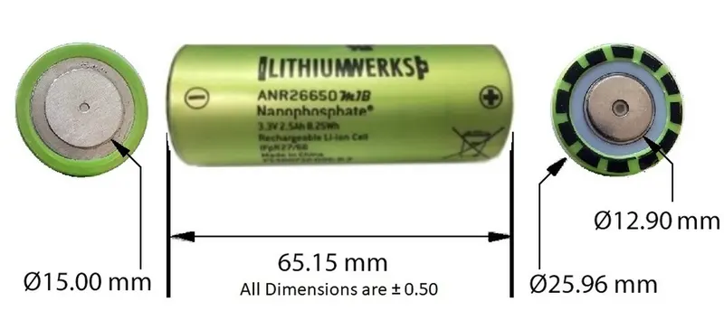
Volume of the cylinder: `pir^2h`
From the Datasheet of Cell, we have 'r' and 'h' values
r=0.013m and h=0.065m
Volume of the cell = `pir^2h` = 3.14 * 0.013^2 * 0.065 = 0.0000344929`m^3`
Cell Energy = Cell Capacity (Ah) × Cell Voltage (V)
= 2.5 × 3.3
= 8.25 Wh
Total volume of the Battery Pack = no of cells * Volume of single cell
= 2182 * 0.0000344929
= 0.0752635`m^3`
Energy density of the Battery Pack = volume * battery pack energy
= 0.0752635 * 1800
= 1354.743 kWh/m^3
Weight of the Battery Pack = No of cells * weight of the single cell.
= 2182 * 0.076
= 165.832 kg
Battery Pack construction:
Length of casing (L) = number of cells at series*(cell diameter (26) + margin at both side of cell (4)) + clearance at side (diameter of edged cell + margin)
L = 122*30 + 60
L = 3720 mm
Breadth of casing (B) = number of cells at parallel*(cell diameter (26) + margin at both side of cell (4) + clearance at side (diameter of edged cell + margin)
B = 18*30 + 60
B = 600 mm
Height of casing (H) = 65+35 (Height of cell + margin for wiring ,Cell holders and metal strips)
H = 100 mm
There are 3 steps for the construction of the battery pack.
1)Battery holding and providing the spacing between the batteries.
2)Connect the batteries with the strips (Series or Parallel).
3)making and manufacturing the battery enclosure housing with the thermal management system and BMS.
1)Holding and spacing:
The primary purpose of a battery holder is to maintain cells fastened in place safely and securely. It is also used to maintain cells in a good arrangement to reduce mechanical vibration and improve the thermal runway between the gaps between the cells. Polypropylene or nylon bodies rated for 80-100 °C make up the majority of the cell holder's body.
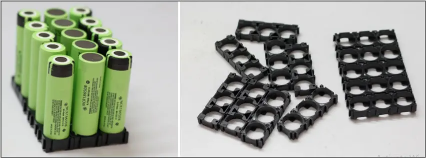
- To create a large battery module, all of the cells must now be connected.
- Therefore, it is crucial that these holders offer the necessary space between the batteries and hold them securely.
- The end cap of the cell features a vent that should not be blocked by any mechanical means. Blocking the cell vent and then sufficiently abusing the cell so as to build pressure in the cell.
- The vent must be able to open in the event of a defect, and there must be a minimum of 1mm between each cell. The contact plate can be placed between the cells with the help of holders.
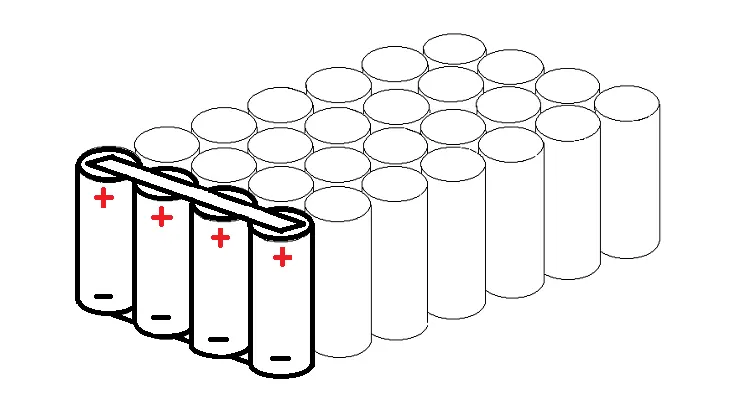
Cells in series connection:
Series cell connections simply increase the pack's voltage; they have no effect on the pack's amps or capacity.
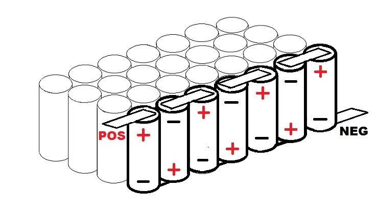
Cells in Parallel connections:
Multiple cells will behave as though they are one giant cell if their electrodes of the same type are connected in parallel. Additionally, when you initially link them together, They need to be at the same charge level.
2) Connecting the cells:
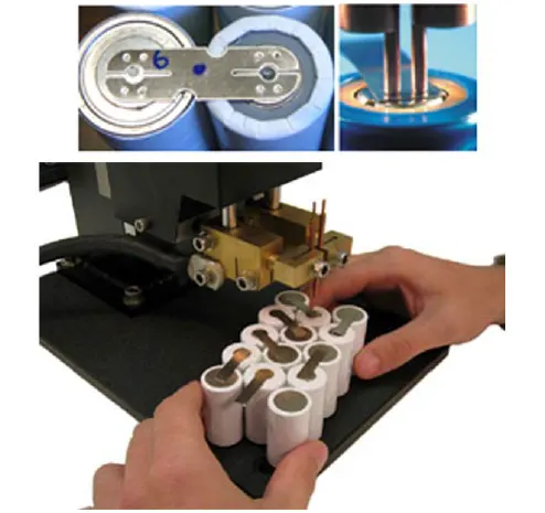
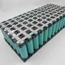
- To achieve the required results, the cells must be connected correctly in series or parallel after being placed in the holders.
- Typically, the connection between the cells is made using a nickel strip.
- Battery construction typically makes use of nickel strips.
- This is because it works well for soldering and spot welding and has good corrosion resistance over time.
- The transfer of current between batteries won't be impacted.
Joining technologies of cells: The interconnections between cells/modules are practiced by various welding techniques. Some of them are,
- Ultrasonic metal welding.
- Resistance welding.
- Laser beam welding.
- Wire bonding.
- Mechanical Joining.
Spot resistance welding: Resistance spot welding is one of the earliest types of welding (RSW). Through the use of an electrical current and pressure between two electrodes, two or more metal sheets can be joined using the RSW process. Without the introduction of filler material or gases, the electrical resistance of the materials at the interface generates heat and melts the materials together.
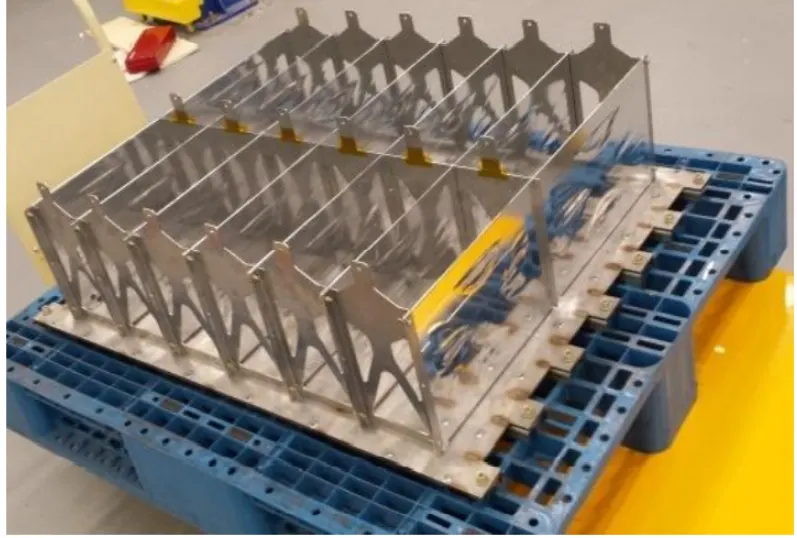
3)Battery enclosure and thermal management of battery and BMS
- The battery's final layer of defense is the enclosure. Therefore, the battery enclosure needs to be both exceedingly sturdy and lightweight.
- Because batteries have a tendency to catch fire in the event of an accident if they leak during a collision, the battery module is enclosed in a highly sturdy enclosure for safety.
- To achieve the best possible range, the weight should be lower.
- When necessary to obtain the most performance out of the batteries, a temperature management system is installed in this metal container to cool and heat the batteries.
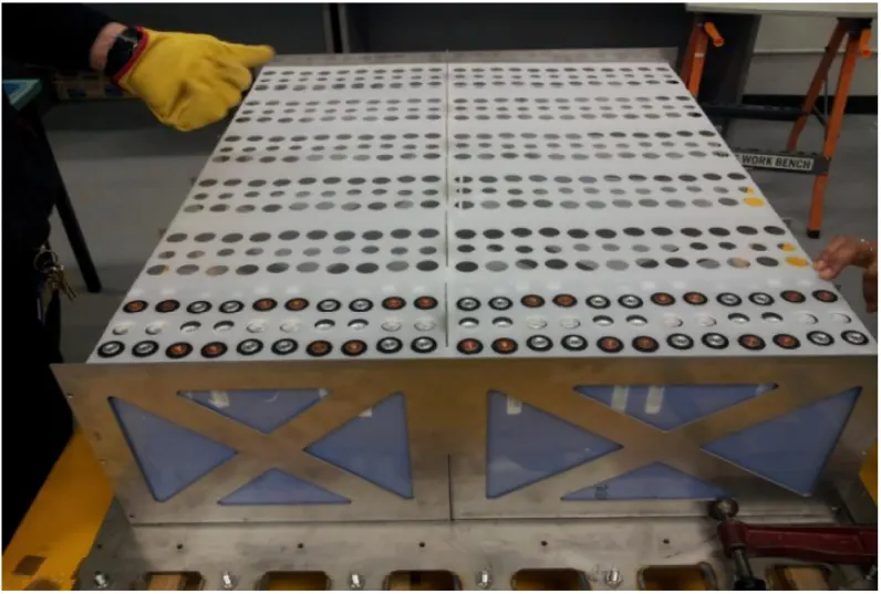
- To construct a whole battery pack, a number of types are connected in both series and parallel.
Conclusion:
| NO | Calculated Parameters | Value |
| 1 |
Cell Volume |
0.0000344929m^2 |
| 2 | Cell Energy | 8.25Wh |
| 3 | Pack assumptions | 122s 18p |
| 4 | Total no of cells | 2182 |
| 5 | Voltage | 400V |
| 6 | Capacity | 45Ah |
| 7 | Energy | 18kWh |
| 8 | Total volume | 0.07526m^3 |
| 9 | Total Density | 1354.74kWh/m^3 |
| 10 | Weight | 165.83kg |