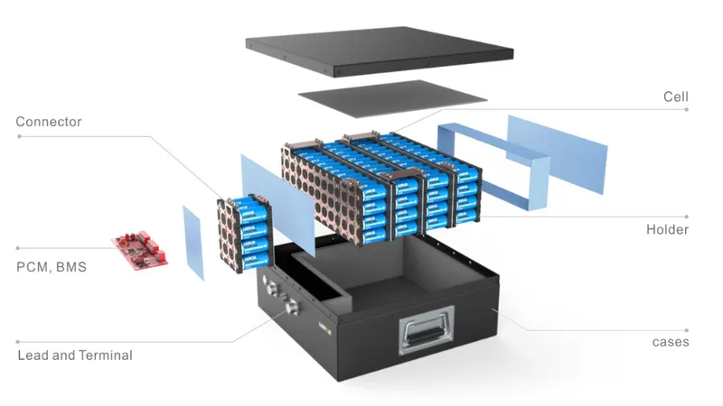
Project 1 Mechanical design of battery pack
Aim : To explain the all details about the ANR26650M1-B cell for 18kWh capacity.
Objective :
1. To study about the connection
2. To understand the Design and thire connection as per requirment.
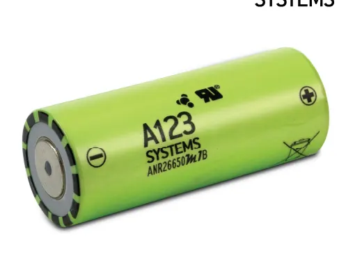
Nanophosphate High Power LithiumIon Cell ANR26650M1-B
A123’s high-performance Nanophosphate lithium iron phosphate (LiFePO4) battery technology delivers high power and energy density combined with excellent safety performance and extensive life cycling in a lighter weight, more compact package. Our cells have low-capacity loss and impedance growth over time as well as high usable energy over a wide state of charge (SOC) range, allowing our systems to meet end-of-life power and energy requirements with minimal pack oversizing.
The Lithium Werks ANR26650M1-B is the next generation of a pioneering 26650 cylindrical cell, now with greater power and energy density and lower impedance. This versatile lithium-ion cell is suitable for a wide variety of applications and system designs. Proven performance in the toughest conditions, combining durability, reliability, and safety, the ANR26650 cell offers an excellent combination of price-performance.
Nanophosphate battery technology offers stable chemistry, faster charging, consistent output, excellent cycle life and superior cost performance. It provides the foundation for safe systems while meeting the most demanding customer requirements. Multiple layers of protection are employed at the chemistry, cell and system level to achieve an energy storage solution with superior safety and abuse tolerance compared to metal oxide lithium-ion chemistries.
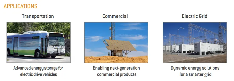
APPLICATIONS
COMMERCIAL SOLUTIONS
Advanced lead acid replacement batteries for
1. Datacenter UPS
2. Telecom backup
3. IT backup +Autonomously guided vehicles (AGVs)
4. Industrial robotics and material handling equipment
GOVERNMENT SOLUTIONS
1. Military vehicles
2. Military power grids
3. Soldier power
4. Directed energy GRID SOLUTIONS
5. Frequency regulation
6. Renewables integration
7. Reserve capacity
8. Transmission and distribution
TRANSPORTATION SOLUTIONS
Hybrid, plug-in hybrid and electric vehicle battery systems for
1. Commercial vehicles
2. Off-highway vehicles
3. Passenger vehicles
ANR26650M1-B TECHNICAL DATA
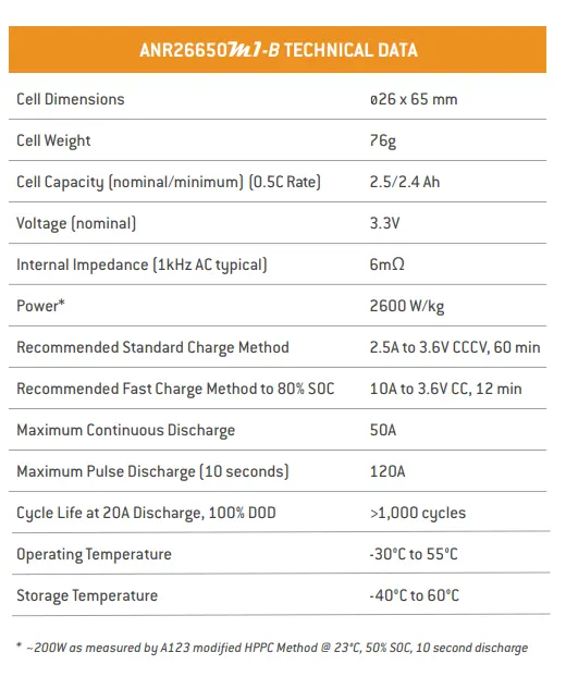
ANR26650M1-B Specifications
Nominal Ratings
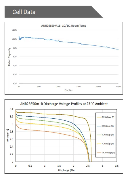
Voltage: 3.3 Volts
Capacity: 2.5 Ah
Energy: 8.25 Wh
Specific Power: 2600 W/kg
Impedance (1KHz AC Typical) 6 mΩ
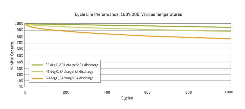
Cycle Life at 1C/1C, 100% DOD: > 4000 cycles
Cell Type: 26650 Lithium-Ion Power Cylindrical Cell
Discharging
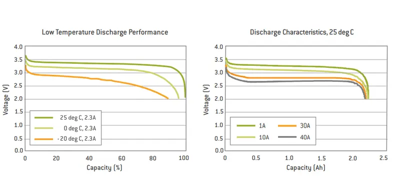
Max Continuous Discharage: 50 A
Max Pulse Discharge Current >50% SOC (10s): 120 A
Minimum Voltage: 2 Volts
Temperature: -30ºC to 55ºC
Charging
Recommended Standard Charge: 2.5 Amps
Max Charge Rate: 10 Amps
Max Pulse Charge Current <50% SOC (10s): 25 A
Float Voltage: 3.45 Volts
Recommended charge V & Cut-off Current: 3.6 Volts, taper to 125mA
Temperature
(Reduce charging current to 250mA when under 0ºC): 0ºC to 55ºC
Mechanical
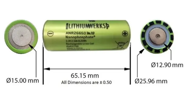
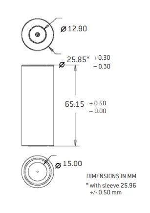
Diameter: Ø25.96 +/- 0.5 mm (1.0")
Length: 65.15 +/- 0.5 mm (2.6")
Mass: 76 g
Certifications
Transportation: UN 3480 (UN38.3), CIQ
Safety: UL 1642, IEC 62133
Battery Pack Use
When charging and discharging a battery pack, the current and voltage applied to any cell in the pack shall not be exceeded for the given conditions under which the cell are exposed. Appendix A details the limits the cells must be kept within for a given cell’s temperature and cell’s state of charge. This section covers the following topics:
Charger Limits
When charging or recharging Lithium Werks cells in a battery pack, the charger should limit its output current and voltage to match that of the battery pack configuration. During a recharge, the charger shall apply a constant current (CC) charge followed by a constant voltage (CV) charge. In addition, the charger shall cease charging when either:
- Any one cell in the series string, has exceeded its maximum recommended charge voltage, or
- The temperature measured in the pack has gone outside the recommended range for charging.
To achieve maximum life, reliability, and safety, Lithium Werks recommends using cell balancing circuitry to prevent an increasing spread between highest and lowest battery states of charge. Refer to Cell Balancing on page 43 for more information. To determine the charge current for a parallel string of cells, multiply the number of parallel cells in the string by the recommended charge current for a single cell. Note that this calculation does not take into account limitations imposed by any protection electronics or any other features of the battery pack assembly.
Calculation as per assumptions:- 18kWh Battery Pack
basically, 18kWh is energy require to achieve the vehicle its proper range. It is depending upon the voltage (V) parameter and ampere-hour or capacity (Ah).
Here we design a high voltage battery pack for an electric vehicle to achieve its range up to 220 km. For this calculation
I assumed 145.2 V a nominal voltage for series connection.
Basically, the value of the volume of the cell is used to find out the total volume of the battery pack.
Single Cell Energy (Wh) = Cell Capacity (Ah) x Cell Voltage (V) = 2.6 x 3.3 = 8.58 Wh
The value of a single cell is used to calculate the total energy of the battery pack.
Single Cell Energy Density
Volumetric energy (Wh/m^3) = Single Cell Energy / Volume of each cell
= 8.58 Wh / 0.03451 m^3 = 248.62 Wh/m^3
Gravimetric energy (Wh/kg) = Single Cell Energy / Single Cell Mass
= 8.58 Wh / 0.076 kg = 112.89 Wh/kg
Calculation of High Voltage Battery Pack
For design and calculation of battery pack here, I assume a vehicle to achieve 250 km in 18 kWh battery pack. Also, I assume 145.2 nominal voltage for series connection.
So,
Vehicle Range = 250 KM (assumed)
Battery Pack capacity = 18.121 kWh or 18120.96 Wh (For better and accurate calculation here I change kWh)
Now,
We will calculate per km average energy = 18120.96 / 250
= 72.483 Wh/km
Therefore,
Battery Pack total energy = Average energy x km
= 72.483 x 250
= 18120.96 Wh or 18.120 kwh
assume the
Nominal voltage for series connection = 145.2 V ( this depends upon the motor power so we decide the value according to the motor specification or used in vehicle )
To calculate the number of cells connected in series
= Nominal voltage of series connection / Nominal voltage of a single cell
=145.2 V / 3.3 V
= 44
44 Cells will be connected in a series connection to provide a proper voltage.
Energy for battery pack (wh)
= No. of cells connected in series x Single-cell energy
= 44 x 8.58 wh
= 377.52 wh
To calculate no of cells connected in parallel
= Battery pack total energy (wh) / Energy for battery pack (wh)
=18120.96/377.52
= 48
48 cells will be connected in parallel to provide a proper capacity power.
Battery pack total energy (wh)
= No. of cells connected in parallel x Energy for battery pack (wh)
= 48 x 377.52
= 18120.96 wh or 18.120 kWh
Battery pack capacity
= No. of cells connected in parallel x Single cell capacity (Ah)
= 48 x 2.6 Ah
= 124.8 Ah
The value of battery pack capacity is used for the total power required by the vehicle.
Total number of cells for battery pack
= No. of cells connected in parallel x No. of cells connected in series
=48x44
= 2112
2112 Cells will be used to make a complete battery pack.
Mass of battery pack
= Total no. of cells for batter pack x Mass of single cell
= 2112 x 0.076 kg
= 160.512 kg
it is the total weight of cells connected in parallel and series.
Total volume of the battery pack
= Total no. of cells for batter pack x Volume of single cell
= 2112 x 0.0345
= 72.89 m^3
This is the volume of2112 cells which are used in the battery pack system.
Cell peak current (A)
= C rate (Max Pulse Charge Current) x Single cell capacity
= 20 x 2.6
= 52 A
Battery pack peak current (A)
= Cell peak current x No. of cells connected in parallel
=52X48
= 2496 A
It is used for the operation of the battery pack. By this way, a vehicle will decide how much power is required to move.
Battery pack peak power (W)
= Battery pack peak current x Voltage of series connection
= 2496 A x 145.2
= 3624192 or 362.42 W
Cell continuous current (A)
= Crate (Max Continuous Charge Current) x Single cell capacity
= 10 x 2.6
= 26 A
Battery pack continuous current (A)
= Cell continuous current x No. of cells connected in parallel
= 26 x 48
= 1248 A
This is the power which is supply continue to the whole battery pack system.
Battery pack continuous power (W)
= Battery pack continuous current x Voltage of series connection
=1248 x145.2
= 18120.96 or 18.120 Kwh
as we know now
Power (p)= Voltage (v) * Current (i) kw
3.3 *2.5 =8.25 kw
To get 18kwh ,we are assuming 48s 48p
i.e; 48*48 =2304 cells
series connection gives 48*3.3 =158.4 v
parallel connection gives 48* 2.5 =120 A
from this we can get
158.4* 120 =19.008 kwh energy or capacity.
we design battery pack for 48s and 48p cell along with battery spacers to hold cells and for their connection nickel strip is used
when cells are connected by nickel strip spot welding should be used so that cell not get damage.
Choosing the Right Battery Strips :
To make the battery pack, we have to connect the 2112 cells together by means of Nickel strips or thick wire. Generally, Nickel strips are widely used for this. In general, two types of nickel, strips are available in the market: nickel-plated steel strips and pure nickel strips. I will suggest buying a pure nickel. It is a little bit costlier than nickel-plated steel, but it has much lower resistance. Low resistance means, less heat generation during the charging and discharging, which leads to longer useful battery life. Nickel strips come with different dimensions and lengths. Choose the strips according to the current rating
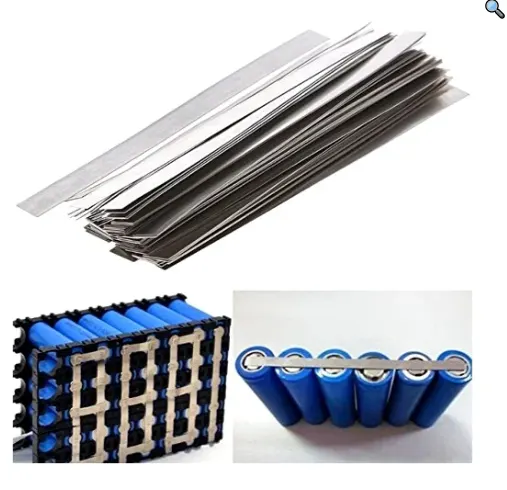
We have two options two connect the 18650 cells together: 1. Soldering 2. Spot Welding
The best choice is always Spot welding, but Spot Welder is much costlier than a good quality Soldering Iron.
Soldering :
We should know why Spot welding is preferred over soldering, the problem with soldering is that we apply a lot of heat to the cell and it doesn’t dissipate very quickly. This enhances the chemical reaction in the cell which damages the cell's performance. Ultimately, we will lose some capacity and life of the cells.
But if we are not interested to buy a costly Spot Welder, we can solder the nickel tabs to the cell by following some precaution and tricks :
- To minimize the contact time of our soldering iron on the cell, make sure the surface is scuffed up sufficiently and we use plenty of flux to allow for fast solder flow.
- It is better to have a good quality high wattage ( min 80W ) iron with good thermal capacity so it can deliver the heat to the joint quickly so we don't have to hold the iron to the battery for ages and let the heat seep into it, causing damage to the battery.
Spot Welding :
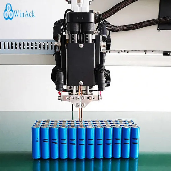
The reason we spot weld because it securely joins the cells together without adding much heat to them. There are two grades of spot welders currently available in the market: hobby grade and professional grade. A decent hobby-grade Spot welder costs around $200 to $300, whereas a good professional grade may cost around ten times more.
Checking the Cell Voltage
Before connecting the cells in parallel, first, check the individual cell voltages. For paralleling the cells, the voltage of each cell should be near to each other, otherwise, a high amount of current will flow from the cell with a higher voltage to the cell with a lower voltage. This can damage the cells and even result in fire on rare occasions.
If you are using brand new cells, the cell voltage is near 3.2 V to 3.4 V, you can join them together without worrying much. But if you are going to use an old laptop battery, be sure the cell's voltage is nearly the same, otherwise, charge the cells to the same voltage level by using a good Li-Ion Battery Charger.
Battery Pack Capacity and Voltage
We have already calculated the number of cells required. First, we have to integrate cells for a module. We know a module consists of 3 series and 5 Parallel cells. The place holder helps us to arrange the cells in the module properly. Strips are placed such a way that the module is connected with 3 series cells and 5 Parallel cells.
Spot Weld the Nickel Strips
Now it is time to know the procedure for using the Spot Welder. The Spot welder has three welding choices: fixed welding head, fixed welding head with foot switch, movable spot-welding pen with the footswitch. I prefer to use the second option. Before welding, you have to prepare the nickel strips and welder.
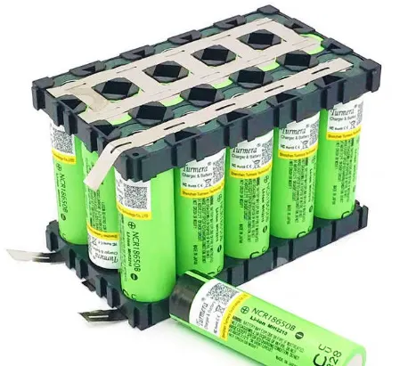
Weld the Battery Strips :
This spot welder can be used to weld the pure nickel as well as nickel-plated steel strips. You have to adjust the welder pulse and current knob according to the thickness of the nickel strips.
For 0.15 mm nickel strips, press the pulse knob 4P and current knob to 4-5. Similarly for 0.2 mm nickel strip, press the pulse knob 4P,6P, and current knob to 7-8. Make sure the welding pen is compressed with the nickel strip and battery terminal, then press the footswitch. You will notice a small spark and two-dot mark on the strip.
Successful Welding :
You can check the weld quality by pulling on the nickel strip. If it doesn’t come off with hand pressure or requires a lot of strength, then it’s a good weld. If you can easily peel it off, then you have to increase the current.
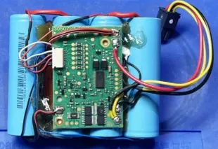
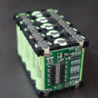
Adding the BMS :
A battery management system (BMS) is an electronic system that manages a lithium battery pack and the main functionalities are
- Monitors all of the parallel groups in the battery pack and disconnect it from the input power source when fully charged ( near 4.2V )
- Balance all the cells voltage equally
- Doesn't allow the pack from over-discharged.
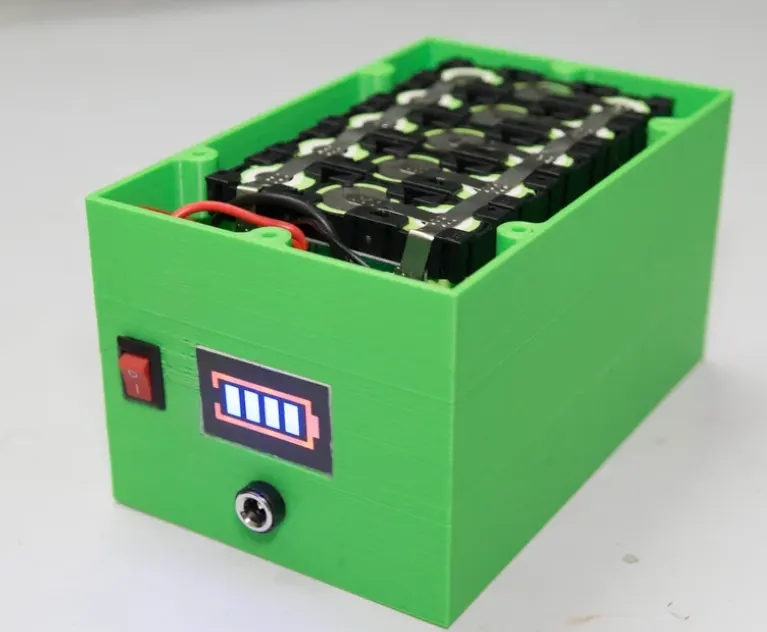
Final Assembly