Project 1 Mechanical design of battery pack
AIM:
Mechanical Design Of Battery Pack
OBJECTIVE:
Battery pack capacity: 18 kWh
Cell: ANR26650M1-B
To Prepare a detailed battery pack drawing along with its enclosure.
INTRODUCTION:
Details Of Battery:Nanophoshate Technology 26650 Lithium Ion Power Cell
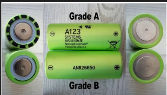
26650 cells are best for Power.Safety.Life applications. They deliver very high power due to their use of patented Nanophosphate battery technology. Based on lithium iron phosphate chemistry (LiFePO4), the cells are inherently safe over a wide range of temperatures and conditions Whether the application requires outstanding cycle life or stable float reliability,
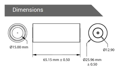
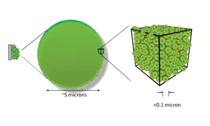
- Nanophosphate battery technology offers thermal-stable chemistry, faster charging consistent output
- low capacity loss over time, and superior total cost of ownership (TCO).
- It provides the foundation for safe systems while meeting the most demanding customer requirements
- Multiple layers of protection are employed at the chemistry,
- cell and system level to achieve an energy storage solution with superior safety
- High tolerance compared to metal oxide lithium-ion chemistries.
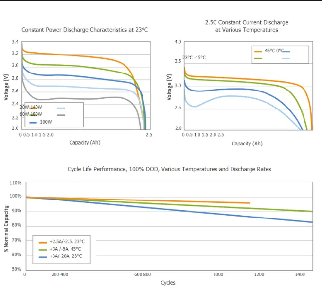
SPECIFICATIONS OF ANR26650M1-B
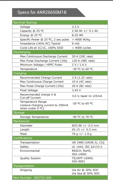
RATED CHARGE AND DISCHARGE CHARACTERSTICS
APPLICATIONS:
• Energy storage
• Frequency regulation
• Uninterruptible Power Supplies
• Communication technologies
• Aviation/Aerospace
• Electrified mobility devices
• Industrial equipment
• Medical devices
• Consumer Products
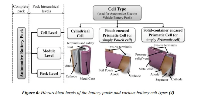
Theory OF Battery
CALCULATION OF BATTERY
Calculation as per the requirement
1.Energy=18Kwh(required)
2.Number of cells (N)
The first thing we need to do is to figure out how many cells will be needed to meet the basic voltage and current requirements of the pack design.
(N)=Energy/(Nominal Voltage *Capacity)
`N=18000/(3.3*2.5)`
N=2182 Nos
The Total no of cells required to get 18Kwh Energy is 2182 no of cells.
Based on this no we need to decide the configuration of series and parallel.
with the desired pack voltage we can easily calculate the number of cells needed to create the system voltage. The system voltage is generally based on thevoltage need for the electric motor(s) in the system.The target voltage is assumed to be 350 V to run our Vehicle by this it is simple enough to determine how many cells are needed in series to generate that voltage by dividing the pack voltage (Vp) by the cell voltage (Vc):
3.Vp/Vc =number of series cells.
For Desired 350 V pack and using 3.3 V (Nanophosphate cell) it would require 106 cells
`Ns=350/3.3`
Ns=106 cells.
Now we need to find the no of cells which will be connected in a parallel configuration.
4.Np(cell in parallel)=Total no of cell /Ns
Np=2182/106
Np=20.58 no of cells=22 cells
One of the reasons to round up or down here is also to end up with an even number of cells which will allows to divide them equally in the modules that will make up the pack.
Cell architecture=106 cells series and 22 cells parallel is given as 106S22P.
5.Calculating Pack Energy and Capacity
To calculate the pack energy (Ep), We are considering 18-kWh pack , multiply the pack voltage (Vp) by the capacity (Ip).
Ep = Vp × Ip
We know that in parallel configured cell multiplies individual cell capacity as Follow,
Capacity =parallel cell in row*individual cell capacity
Capacity=2.5*22
Capcity=55.0Ah
here we Considered that we are using a 3.3-V nominal Nanophosphate cell and 106 of them in series to get a pack Voltage of 350V and in order to achieve the desired energy we are using 55 Ah of cells. This could be accomplished by using 22 2.5 Ah cells in parallel .
the required capacity is generally determined by the electric motor current requirements and energy is typically determined by the end user based on the application type.
6.To calculate how much current the electric motor or system will need to draw
We have already calculated battery capacity which is 55Ah means it is going to supply 55 A current per hour.
A 55 Ah cell will by definition be able to supply 55 A for a 1-h period and will be able to offer higher power pulses at different rates.
7.RANGE;
if the end-use application is an all-electric vehicle that is targeting about 129Wh/Km of driving range with a system that is capable of providing 70% power train efficiency then
Range=1800/129
Range=139km
So,Our Electrical vehicle is assumed to cover around 139Km with Current parameter
8.Calculating pack energy at End of Life
From above all of these calculations assume that we can use 100% of the battery to achieve that range, in reality we may only be able to use about 80–90% of that battery depending on the cell selection and usage profile That means that the 18kWh must be the amount of energy that is usable in this system design. In other words, we must be able to remove 18kWh of energy from the pack and, therefore, if we are to maintain the safety margins on the top and bottom and only use 80% of the total energy, we will need to determine how much total energy is needed. That means another quick calculation by dividing the usable required energy by 80%
18kWh/80 % = 22.5 kWh total battery pack energy needed.
This means that in order to remove 18 kWh of energy from the pack to achieve the 139 Km range, the battery will really need to be sized up to over 22kWh in order to achieve these goals.
9.Calculating System Power
System power can be calculated by using the formula:
P=I^2 ×R
if the cell that we are using has an internal resistance of 7mΩ, then we cancalculate the power for each cell as follows:
(55 Ah)^2 × 7 mΩ =21.175 W per cell
To estimate the power in kW of a pack by multiplying the total number of cells times the power in watts (W)
2180*21.175=46.203 KW
10.Maximum Continous Discharge
To calculate the maximum continuous discharge current that the system can provide,we need to multiply the number of cells in parallel (Np) times the cell current (Ic) multiplied by the maximum C-rate (CMax) to get the maximum discharge current (IMax Continuous) in amperes.
Np × Ic ×CMax =IMax Continuous
22*2.5*10=550AMax Continuous Discharge
11.Calculating Charge Voltage
Maximum charging voltage is simply equal to the total number of cells in series multiplied by the cell’s maximum voltage as defined by the cell manufacturer.
106 cell × 3.6Vmax=380 V Maximum
Minimum is calculated in the same manner: number of cells in series multiplied by the cell’s minimum voltage as defined by the cell manufacturer.
106 cells × 2V =212 V Minimum
12.Battery Dimensions
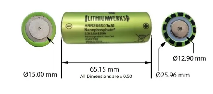
ANR cell has a 26mm diameter and 65 mm height.on the basis of that we need to decide the battery Size for Battery Casing
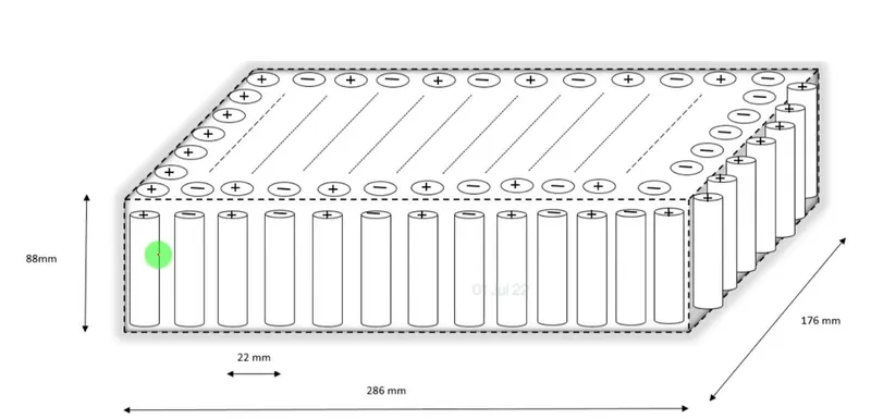
Length of Casing(L)=number of cell at mid*(Cell diameter(26)+margin at both side of cell (4))+clearnance at side(diameter at side (diameter of edged cell+margin)
L=106*(26+4)+60
L=3240mm.
Breadth of casing(B)=cell diameter(26)+marging at both side of cell(4)+clearance at side (diameter of edge cell+margin)
B=22*30+60
B=720mm
Height of casing(H)=65+35(Height of cell+margin for wiring,cell holders and metal strips)
H=100 mm
Weight of battery pack
Cell weight=76 g
no of cells=2182
Battery pack weight(W)=cell weight*no of cells+weight of accessories
W=76*2182+4.5=165.8+4.5=170.3kg
Battery pack Assembly
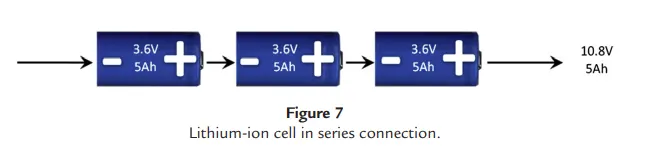
Series—A series configuration refers to a grouping of cells connected in series (e.g.,negative to positive, etc.). Connecting cells in series increases the voltage of the overall system. Putting lithium-ion cells in series is similar to connecting multiple garden hoses end to end, just as the garden hoses are in series so are the batteries. The difference is that in batteries connecting them in series increases the voltage but not the capacity.
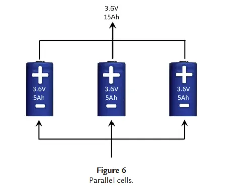
Parallel—A battery with parallel connections refers to cells that are connected in parallel (e.g., positive to positive, negative to negative, etc.). In a parallel connection, we are feeding current into all of the cells at the same time and pulling current out of them at the same time. When connecting cells in parallel, the system capacity is increased.
Battery Pack Components
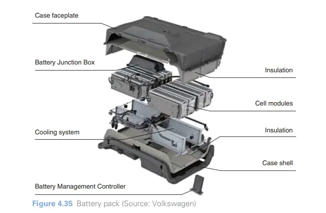
The most common battery technology now is lithium-ion. The complete battery pack consists of a number of cell modules (the actual battery consisting of 200–300 cells), a cooling system, insulation, junction box, battery management and a suitable case or shell. These features combine so that the pack is able to withstand impacts and a wide range of temperatures.
Mechanical Design of Battery Pack Construction:
Using various cell-Module-Pack
Step 1-
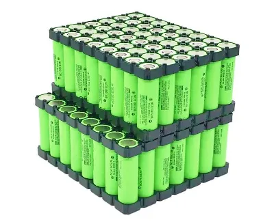
The First step is to start snapping the square cell holder togther.One can use the cell terminal block but they will take more space than a hexagonal block.Lego connectors and Battery Holders are used to connect the battery
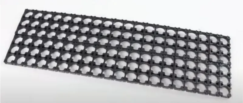
The cells are placed with insulator gasket

Step 2-
Placing the cell in the holder and put the second holder in the place Cell Fixtures the better Housing to be designed for the Battery pack
Step 3-
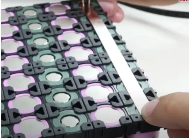
Connecting the cells with nickel strips using spot welding process the nickel has a issue in heat generating the SIGMAClad is recommended.The series connection will be made by connecting the positive terminal of the cell to negative terminal.The parallel connection will be made by connectin all the positive terminal to positive side and all the negative terminal to negative side.
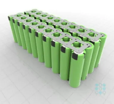
connecting the complete matrix of the cell together
Step 4-
Connecting the heat sink to the Battery pack.Better Pack Fixture Should be given for cooling and Thermal Management
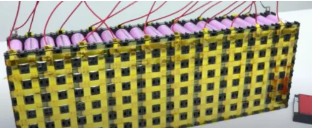
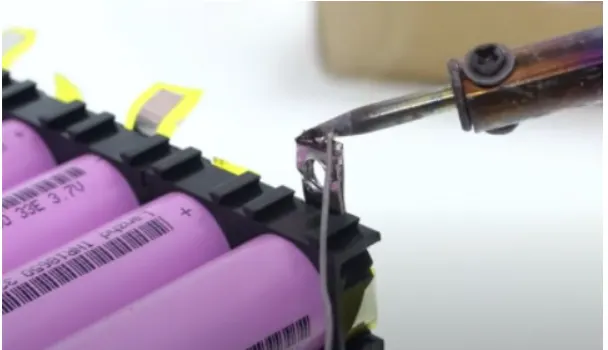
The soldering of battery wire is done to ensure the internal structure of the battery pack is assembled and all the terminals are connected as per the connections.
Step 5-
connect the balancing wire pin to the Battery Management System

Step 6-
After the battery management system the next and final step is to place the battery in Enclosure
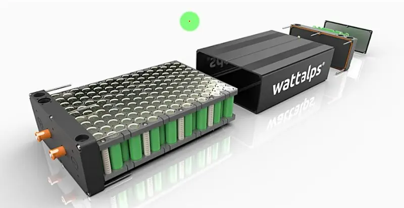
The Complete Battery pack is Designed as shown in the below figure with BMS ,Thermal Management to overcome the Thermal Runaway and meet the high power and High Energy Requirement.
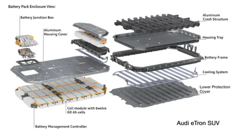
CONCLUSION: The Mechanical Design of the Battery Pack is Designed and Calculated the Basic Calculation of the cell for the given ANR26650M1-B considering the Parameters from the Manufacturers DataSheet to meet the High power and high Energy asumming the required Parameter to meet the requirement for 18Kwh Battery pack capacity.
Reference:file:///G:/My%20Drive/Handbook-of-lithium-ion-battery-pack-design-_-chemistry-components-types-and-terminology-PDFDrive-.pdf