Project 1 Mechanical design of battery pack
Aim-
The Aim of this project to make a detailed report on constructing a fully equipped 18kWh battery pack with using ANR26650 M1-B cell.
Making of A Battery Pack-
To make a battery pack we need to select a cell first, which can be used for creating a battery pack with series and parallel combination. In this project we use an lithium iron phosphate battery with nano phosphate technology and for this we use ANR 26650M1-B cell by A123 manufacturer(datasheet attached). along with this we need to decide connection arrangement with mechanical placement of each cell and all mechanical aspect including encloser and safety measures. then we have to design BMS system for this battery pack along with all calculations needed in cell level + module level + battery pack level.
ANR26650 M1-B Li-ion Cell-
ANR26650 M1-B cells is having 3.3V nominal and 2.6Ah capacity comes in cylindrical design and due to nanophosphate technology it can deliver upto 50A continous discharge current. It has lower energy density and it can supply upto 8.25Wh but kit comes with higher specific power ie. around 2600W/kg, so we can easily drive a high power load without compermising battery life and safety.

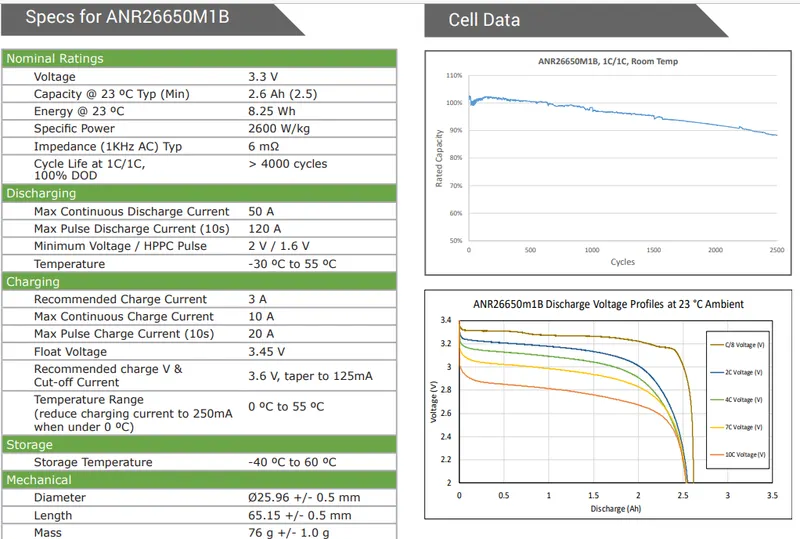
In above figure, the specification of this battery is given in dettailed manner along with the discharge characteristics and thermal effect. and we use this data for plenty of time in our project.
Electrical Connection:- To supply 18kWh with these 8.25Wh cells, we needs 18k/8.25 =2182 cells(min.) which we need to connect in serries and parallel combination such that It can together will be used as 15kWh Battery pack. To go further in this procedure we need to assume operating voltage of battery pack.
In this case we consider 330V nominal value of operating voltage of our battery pack such that 10 modules will together connected in seies and make our 18kWh battery pack. First we have to find operating voltage and Ah capacity of each module. so we do some calculations.
Nominal Voltage of each module = `(330V)/10 =33V`
Ah capacity of Battery pack = Ah capacity of each module(all are in series) = `(18000Wh)/(330V)~~54.6Ah`
So now we know the Voltage and Ah capacity of each module so now we will find the series and parallel connected cells to meet this capacity. Before that I want to do one simple modification, ie. all cells will connect in "xPyS" connection. where, x are the no. of cells in parallel and y is no. of cells in series. The purpose of this connection is to have better balancing of cell's voltage as parallel connected cells always have same operating voltage. therefore, we firstly connect cells in parallel then connect these combination to series.
Now,
No. of cells in parallel per module = module Ah capacity/cell Ah capacity = `(54.6Ah)/(2.5Ah)~~22`
No. of cells in series per module = module voltage/cell voltage = `(33V)/(3.3V)=10`
Now we have 22P10S connected cells in each module and 10such modules are connected in series to form a 330V / 54.6Ah batterypack and we need 22x10x10= 2200 cells to form this battery pack.
Mechanical Design:- Now as we known the connections of the cells, we can talk about the arrangement of the cells, first we talk about the how series and parallel connections are done and their arrangement to reduce the overhang that will reduce the overall resistance of the Battery pack. then we discuss the space required by the Battery pack and then encloser for module with safety features.
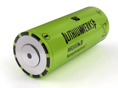
First we discuss the cell level arrangement, as we know the whole body except from the upper portion is the negative terminal of cells so the curvy part of the cylindrrical cells should be electrically isolated that was done by manufacturer itself, they give an insulation(Green) covering the body of the cell except upper and lower part where we do connections.
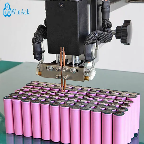
So in this case kwe use spot weld connections with SIGMAclad(Trimetalic strips) because the Discharge capacity of our cells are very high and we need to prevent temperature rise in the connection which is why we're not using pure nickel strips. This strips are used to connect 22 cells in parallel first than 10 such combination is connected in parallel such that all parallel cells are connected along with length of rectangle and series connections as width of rectangle, and the height of the module is equal to the height of cells.
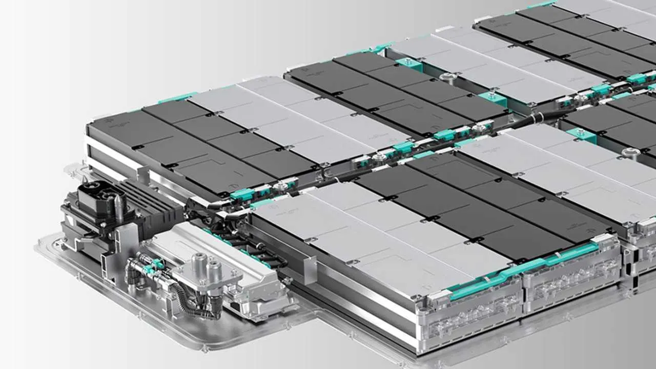
Before going connected by spot welding we install liquid cooled Aluminium fins/strips to remove excessive heat from Battery pack and this strips filled with coolent that will go to radiator to transfer heat to the enviroment.
We also use temperature sensors inside the module in different locations such as centre and among a group of cells to measure body temperature of the cells. and the connections of this sensors along with voltage sensing terminals are take out by using foil based component.
after this we closed this arrangement with take out Two power terminal and sensor connections used by BMS and all this arrangemt will mount on a high grade plastic material and Steel housing with air tight arrangement and one directional protection venting to let gases out the gases from the inside and prevent anytthing to go from outside to inside.
Now we move ahead for calculating the spacee required for Battery pack that include all cells and module along with form factor of battery pack and wiring harness with BMS controller. First we need to calculate the space required by the cell that is given in the datasheet of battery;
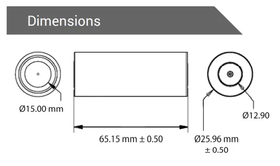
here we can see the cylindrical cell having 65.65mm(max) length and 26.46mm(max) length and such cells are connected to make a module, so now we calculate the space required for one module that includs 22 such cells in length and 10 such cells in width. we take 2mm gap between each cells(exclude volume expansion of cells) for Al strips (heat sink).
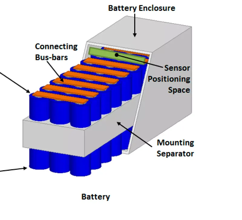
length of encloser = 26.46*22 + 2*(22+1) = 628mm
width of encloser = 26.46*10 + 2*(10+1) = 287mm
Height of encloser = 65.65 + 15 (sensor positioning space) = 82mm
Total volume of encloser = 62.8*28.7*8.2 = 14780 cm^2
Now we talk about the battery pack level spacing where 2x5 modules arrange in ground level and their connection brought out at the inner side abd directly goes along battery pack to the BMS, that is mounted on the side of the Battery pack. therre is also connectors for connecting power cables and communications wires. so we take space between 5 modules negligible but the space in the centre is around 10 cm. and the outer side of the Battery pack is fitted with steel fittings (2cm).
length of battery pack = 2*62.8 + 10 + 4 = 140cm(approx)
width of battery pack = 5*28.7 + 4 = 148cm(approx)
Height of battery pack = Height of module encloser(aprrox) = 8.2cm
Volume require by battery pack = 1.4*1.48*0.082 = 0.17 m^2 (approx)
Total volume including BMS = 0.17 + 0.017(BMS+Connectors) = 0.187 m^2
All the modules and BMS and connectors are mounted on the steel sheet.
Battery Management System:- BMS is mandetories for all High power Battery pack as it provides safety features and also improve Battery performance and lifecycle. In this Battery pack we will provide BMS that monitor 100 Voltages connected in series and maintain this cell voltage with passive cell balancing to use full capacity of battery pack throughout the procedure. then we use one temperature sensor in the centre of the module as this is the hottest area in module. so we got 10 temperature sensors for 10 modules. there are a resistive current measuring device installed in the negative terminal of battery pack such that BMS can monitor the current and charges supplied by the Battery pack, If current is larger than max current limit then BMS will disconnect the Battery pack to the load. and current also monitor regularly to calcullate the SOC of the battery pack.
BMS will instantaniously Disconnect The battery pack in case of any module temperature reaches Higher Temperature limits(we doesn't need lower temp. limits as we assume BMS used in Intertropical region) to avoid thermal runaway, or overcurrent condition of Battery pack, or any of the 100 series connected cell voltages reaches maximum or minimum voltage permissible limits.
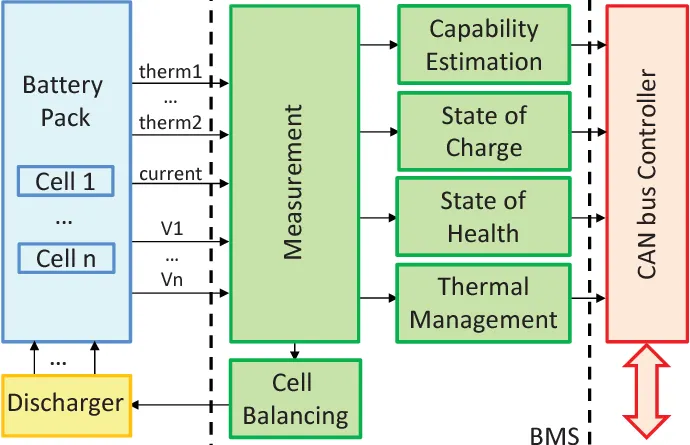
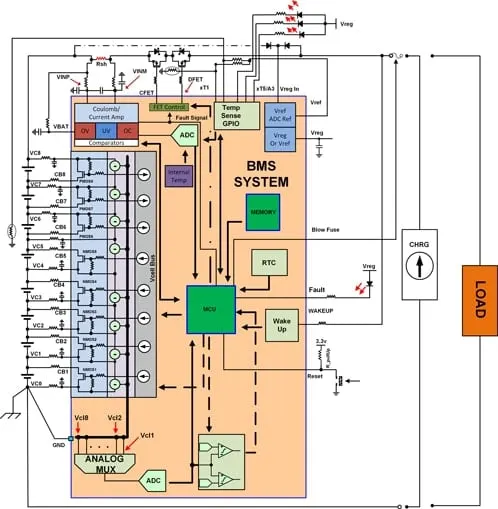
We use Relays instead of FET(architecture) as a main switch and implement Relay control logic instead of FET control. Rest of architecture is same as given in figure which reflects ADC voltage sensor implemented in BMS chip, the current will also measures by measuring voltage across small resistance(I=V/R) and passive balancing of cell is done by controlling FET's connected to each voltage terminal and signal to this FET is given by BMS to maintain cell Voltage difference in limit. The wokeup command is given by user to activate BMS system and all parameters are monitor by MCU of the BMS, MCU is also programmable and give information if asked.
BMS will try create best possible condition to enhance battery performance such as It tries to operate every cells in the permissible limits given by the manufacturer datasheet by maintaining the temperature with controlling coolent flow from the thermal management system and do cell balancing and to limit max discharging current as well as chargers Battery voltage to ensure the higher capacity with good battery life.
BMS also communicate with user and other devices through communication channels for providing information regarding the current operating parameters and also calculate the remaining km range left in case of used in EV. It can also intruppt the supply or making it by taking instructions from user.
BMS limits for this Battery pack:- these limits are taken from the battery datasheet
| Upper Temperature limit | `55^oC` |
| Max cell voltage | 3.45 V |
| Min cell voltage | 2 V |
| Max charge voltage | 3.6*100 = 360V |
| Max charge current | 10*22 = 220 Amp |
| Max pulse charge current | 20*22 = 440 Amp |
| Max continous discharge current | 50*22 = 1100 Amp |
| Max pulse discharge current(10s) | 120*22 = 2640 amp |
| Max cell Voltage Difference(deltaV) | 0.01V |
SOC calculation:- SOC calculations are done by coloumb counting method, where charge outflow of the battery pack is measured by integrating current through time and Divided by th the Total capacity of the Batterypack in Amp-hour. the mathematical logic are programmed into MCU and can be implemented with following equation-
`Q=int((I*dt)/3600)`
SOC = (Total capacity-Q)/Total capacity = 1-DOD