Project 1 Mechanical design of battery pack
Battery pack capacity: 18 kWh
Cell: ANR26650M1-B
Prepare a detailed battery pack drawing along with its enclosure. State your assumptions.
Answer:
ANR26650M1-B cell:
High performance nanophosphate lithium ion phosphate battery technology delivers high power and high energy dendity combine with excellent safety performance and extensive life cycling in a ligher weight, more compact package. Our cells have low capacity loss and impedance growth over time as well as high usable energy over wide state of charge range, allowing our system to meet end-of-life power and energy requirement with minimal pack oversizing.
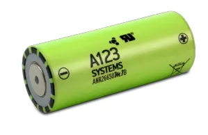
Specification of the ANR26650M1-B cell:
https://www.batteryspace.com/prod-specs/6610.pdf
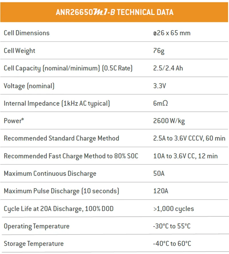
As seen from the specification of cell,
Nominal voltage = 3.3 V
Capacity = 2.5 Ah
So, the energy provided by the battery is calculated as follows:
E = V * I
E = 3.3 * 2.5
E = 8.25 Ah
Required battery pack capacity is 18 kWh
Number of cells required = battery pack capacity/cell capacity
= 18000/8.25
= 2182
As common nominal pack voltages in current vehicles range from 100V-200V for hybrid/plug-in hybrid vehicles and 400V to 800V and higher for electric-only vehicles. The reason for this is higher voltages allow more power to be transferred with less loss over the same diameter (and mass) of copper cable.
Here the nominal voltage for battery pack is assumed as 400 V.
The number of cells connected in the series is calculated as follow:
No. of cells in series = Total voltage/voltage of each cell
= 400/3.3
= 122
Number of cells connected in parallel = 2182/122
= 18
Thus, for 18 kWh capacity of the battery pack, we required 122 series connected cells and 24 parallel connected cells.
Procedure for designing the battery pack:
1)
- First check each cell voltage before connecting in the parallel.
- For the parallel connection of the cell the voltage of the each leg should be same, so the voltage of each cell should be same.
- Otherwise, higher amount of current will flow from the cell from higher voltage to lower voltage.
- This can damage the cell and eventually damage the battery pack and sometime caught fire.
- For the new cell, the cell voltage is near to 3.3 – 3.5 V, you can join them together without worrying much, otherwise charge the cell to the same voltage level by using a good Li-ion battery charger.
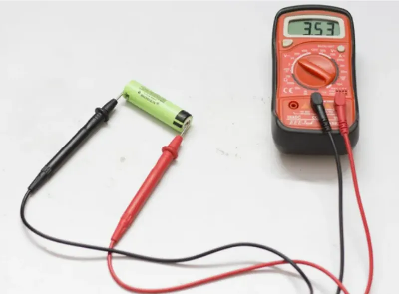
2)
- The cell which has a low voltage is charged by using the battery charger as shown below.
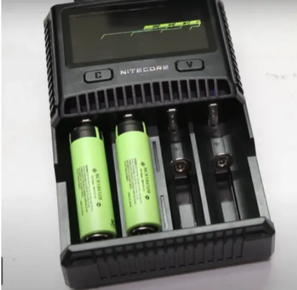
3)
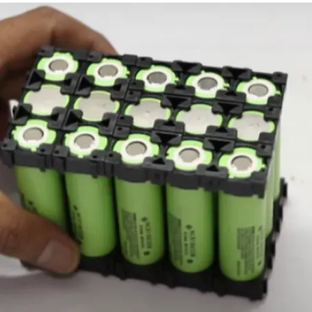
- Now we have to take the battery holder and assembled the cells into it.
- The advantage of using the cell holder are:
- You can make a custom pack of any size according to your requirements.
- It provides space between the cells, which allow fresh air to pass and the battery gets cooled easily.
- It makes your battery solid and reliable.
- It provides safety anti – vibration to your battery pack.
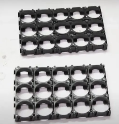
4)
- Now insert cells with positive terminals upward.
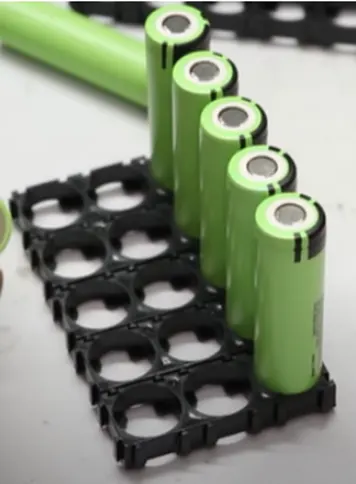
- Now insert the cell in the next row with negative terminals upward.
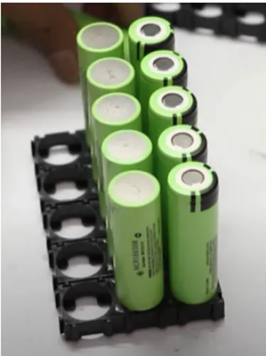
- Again in the next row insert cells with the positive terminals upward.
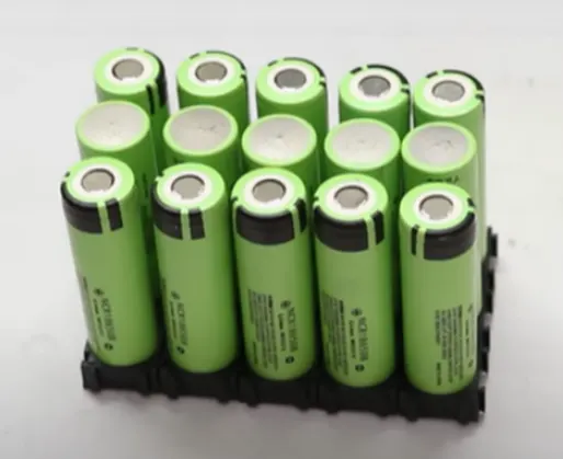
5)
Then align the battery holder and secure it.
6)
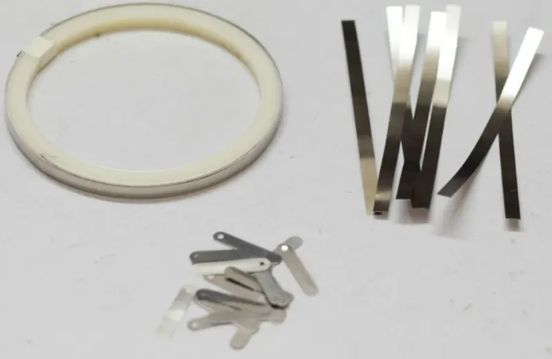
- We have to connect the cells together by means of nickel strips or thick wire to make the battery pack.
- Generally nickel strips are widely made for this.
- In general two types of nickel strips are available in the market.
- Nickel plated steel strips and pure nickel strips.
- Usually pure nickel strips are used.
- It is little bit costlier than nickel plated steel.
- But it has much lower resistance.
- Low resistance means less heat generation during the charging and discharging which leads to longer useful battery life.
- Nickel strips comes with different dimensions and lengths.
- We have to choose the strips according to the current ratings.
7)
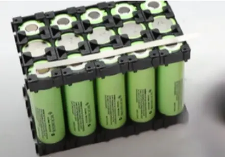
- Then place a nickel strip on the first row.
8)
- Now there are two options to connect the cells together
- Soldering
- Spot welding
Soldering
- Spot welding is preferred over soldering because in soldering we apply lot of heat to the cell and it doesn’t dissipate very quickly.
- This enhances the chemical reaction in the heat which damages the cell’s performance.
- Ultimately we will loose some capacity and the life of the cells.
- But if we are not interested to buy a costly spot welder, we can solder the nickel tabs to the cell by following some precaution and tricks.
- To minimize the contact time of your soldering iron on the cell, make sure the surface is scuffed up sufficiently and you use plenty of flux to allow for fast solder flow.
- It is better to have a good quality high voltage iron with good thermal capacity so it can deliver the heat to the joint quickly so you don’t have to hold the iron to the battery for ages and let the heat seep into it causing damage to the battery.
Spot welding
- The reason we spot weld because it securely joins the cells together without adding much heat to them.
9)
- By using the spot welding spot the nickel strip on each cell of first row.
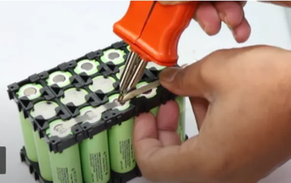
- Then spot the nickel strips on 2nd negative terminal row and last positive terminal row as shown.
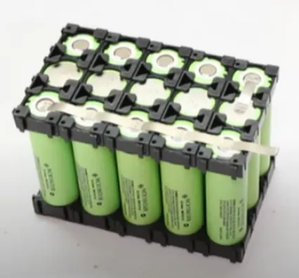
- Similarly spot weld long nickel strip to last row positive terminals of cells and repeat same procedure on bottom side.
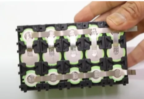
10)
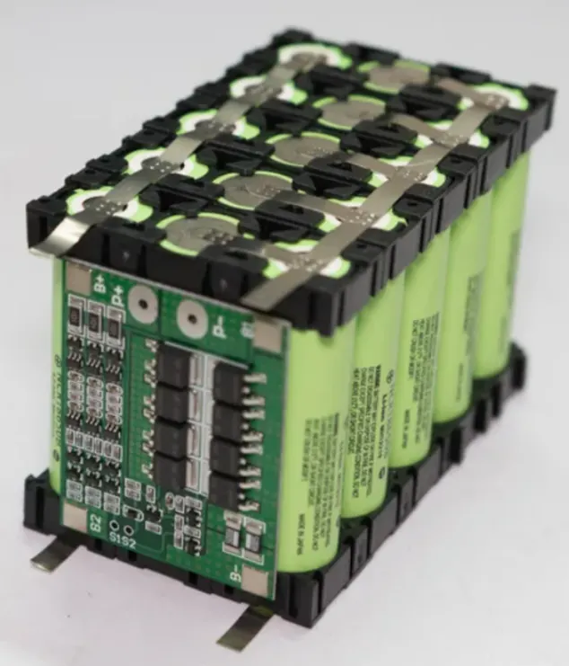
Take battery management system
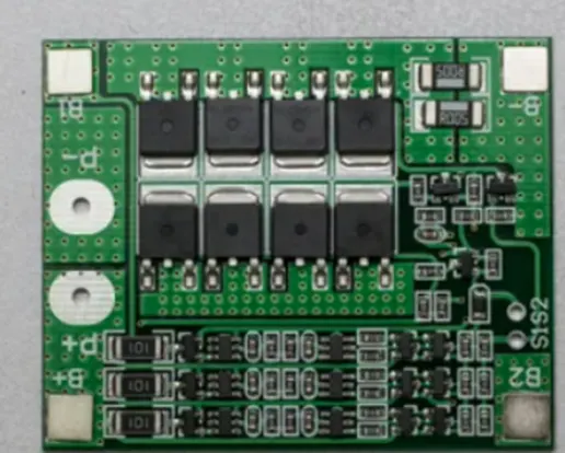
Then connect the BMS as shown in the below diagram. The BMS has four soldering pads B-, B1, B2 and B+. We have to connect the first parallel group negative terminal bus to the B- and positive terminal bus to the B1. Similarly the third parallel group negative terminal bus to the B2 and positive terminal bus to the B+.
We can spot weld the nickel strips to the BMS or solder it to the PCB pad. We prefer to solder the nickel strips to the PCB for a sturdy connection. First apply soldering flux to the PCB pads and end of the nickel strips. After that tin all the pads by applying a little amount of solder and then solder them together.
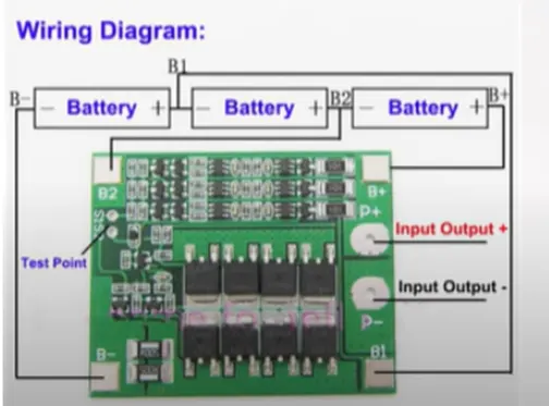
11)
Place a BMS on a battery pack and connect BMS to battery pack as shown in wiring diagram.
12)
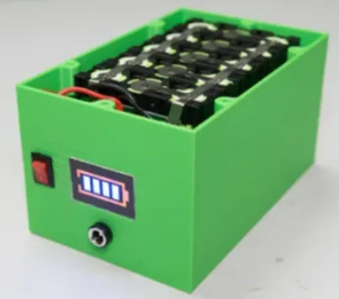
Now take a casing and place that battery pack inside that casing.

To calculate the dimensions of battery pack:
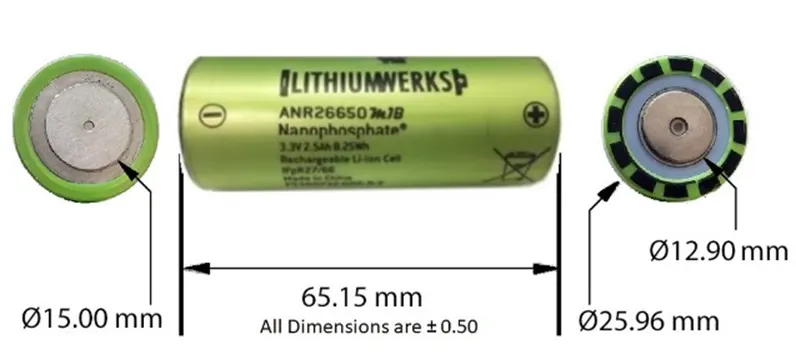
Dimension of a ANR26650M1-B cell:
In the battery pack we design there 122 series cells and 18 parallel cells
Length of the battery pack = (no. of cells in series*cell diameter) + (no. of cells in series-1) * 4mm + 10mm
Length of battery pack = (122 * 25.96) + (122-1) * 4 + 10 = 3661.12 mm
Breadth of battery pack = (no. of cells in parallel * cell diameter) + (no. of cells in parallel-1) * 4mm + 10mm
Breadth of battery pack = (18*25.96) + (18-1) *4 + 10 = 545.28 mm
Height of pack = height of cell + 2mm * 1mm of bus plate + space for ventilation
Height of pack = 65.15 + 2 * 1 + 2.85 = 70 mm
Design options available are
- Aluminium, 10 mm base plate
- Stainless steel, 5 mm base plate
- Stainless steel, 4 mm base plate
To calculate the outer dimensions of the battery pack
1. Aluminium, 10 mm base plate
Length = 3661.12 +20 = 3681 mm
Breadth = 545.25 + 20 = 565.25 mm
Height = 70 + 20 = 90 mm
Volume = final volume – initial volume
Volume = (3681.12*565.25*90) – (3661.12*545.25*70)
Volume = 47531979 mm^3
Density = 0.003 g/mm^3
Thus mass = volume * density = 142595 g = 143 Kg
2. Stainless steel, 5 mm base plate
Length = 3661.12 + 10 = 3671.12 mm
Breadth = 545.25 + 10 = 555.25 mm
Height = 70 + 10 = 80 mm
Volume = final volume – initial volume
Volume = (3671.12*555.25*80) - (3661.12*545.25*70)
Volume = 23335352 mm^3
Density = 0.007 g/mm^3
Thus mass = volume * density = 163347 g = 164 Kg
3. Stainless steel, 4 mm base plate
Length = 3661.12 + 8 = 3669.12 mm
Breadth = 545.25 + 8 = 553.25 mm
Height = 70 + 8 = 78 mm
Volume = final volume – initial volume
Volume = (3669.12*553.25*78) - (3661.12*545.25*70)
Volume = 18599572 mm^3
Density = 0.008 g/mm^3
Thus mass = volume * density = 148796 g = 149 kg
The battery pack design with stainless steel, 4 mm base plate is most suitable because though its weight is more than aluminium, 10 mm base plate but the stainless steel, 4 mm base plate design saves a lot of space than aluminium, 10 mm base plate design.
Results:
For battery pack capacity: 18 kWh
And cell: ANR26650M1-B
We require 122 series connected cells and 18 parallel connected cells.
Battery pack dimension
Inner dimension = 3661.12 mm * 545.25 mm * 70 mm
Outer dimension = 3669.12 mm * 553.25 mm * 78 mm
The pack material is stainless steel, 4 mm base plate