Project 1 Mechanical design of battery pack
Project- (1):- Mechanical design of battery pack.
Objective:-
- Battery pack capacity:- 18 kWh
- Cell:- ANR26650M1-B
- Prepare a detailed battery pack drawing along with its enclosure. State your assumptions.
Introduction:-
- An Energy storage system is a device which store energy, discharge and also get charge, The common type of Energy storage system used Electric Vehicle applications and Chemical Batteries, Ultracapacitors, Supercapacitor, and Fuel cell. There are a few basic parameters which must be taken into consideration while selecting and Electric Vehicle.They are Specific Energy, Specific Power, Efficiency, Maintenance requirement,cost, environmental adaption,Friendliness and safety.of all these,Specific Energy is the most important parameter as the total range of the vehicle can be obtained from it.
Electrochemical Batteries:-
- The Electrochemical Batteries are energy storage systems which convert the chemical energy into Electrical Energy.A Battery is a collection of individual cells stacked to gether.Each invidual cell processes. The major component of a cell are the positive electrode, the negative electrode and the electrolyte.
Types of Battery Technologies:-
There are mainly 3 type of battery Technologies used in Electric Vehicle:-
1] Lead Acid Batterys:-
- The Lead Acide battery are of low cost, have relatively high power capability and also have a good cycle.It is the oldest type of electrochemical battery.These have a very low energy density and below 10 deg c the specific power and energy are greaty reduced.
2] Nickel batted Batteries:-
- Nickel is lighter than Lead and also has excellent electrochemical properties. There are 3 mojor types of Nickel Based batteries:-
(i) Nickel / Iron Batteries
(ii) Nickel/ Cadmium Batteries
(iii) Nickel/Metel Hydride batteries
3] Lithium Based Batteries:-
- Lithium is the lightest of all metels and has excellent electrochemical properties. It's highniminal voltage leads to its high specific energy and power. There are mainly two types of Lithium Based Batteries.
(i) Lithium Polymer Batteries:-
- It has Lithium and Metal intercalation oxide as the negative and positive electrode respectively. It has solidified polymer as the electrolyte and has a nominal voltage of 3V.
(ii) Lithium Ion Batteries:-
- This is considered the battery of the future.Its negative electrode is lithiated carbon intercalation material instead of metallic lithium and Its positive electrode is lithiated transition metel intercalation oxide.the elctrolyte is either liquid organic solution polymer and each cell has a nominal voltage between 3.5 -4 V.
Working of a Battery:-
- There are two major activities which take place in every cell. During discharge, the negative elctrode or the anode reacts with the elctrolyte and gauns excess of electrons. These electrons are then passed to the positive electrodes and the positive elctrode reacts with the electrolyte and also gains the two excessive electrons transferred from the negative electrode. This is how electricity is generated in each cell.The Charging of the cell is more or less the opposite process of Discharge.
What is Battery Pack:-
- A battery pack is a set of any number of (preferably) identical battery or individual battery cell. They may be configured in a series, parallel or a mixture of both to deliver the desired voltage, capacity, or power density. The term battery pack is often used in reference to cordless tools,RC toy Car and BEV.
- Components of battery packs include the individual batteries or cells, and the interconnection which provide electrical conductivity between them. Rechargeable battery packs often contain a temperature sensor, which the battery charger uses to detect the end of charging. Interconnects are also found in batteries as they are the part which connects each cell, though batteries are most often only arranged in series strings.
- When a pack contains groups of cells in parallel there are differing wiring configurations which take into consideration the electrical balance of the circuit. Battery Regulators are sometimes used to keep the voltage of each individual cell below its maximum value during charging so as to allow the weaker batteries to become fully charged, bringing the whole pack back into balance. Active balancing can also be performed by battery balancer devices which can shuttle energy from strong cells to weaker ones in real time for better balance. A well-balanced pack lasts longer and delivers better performance.
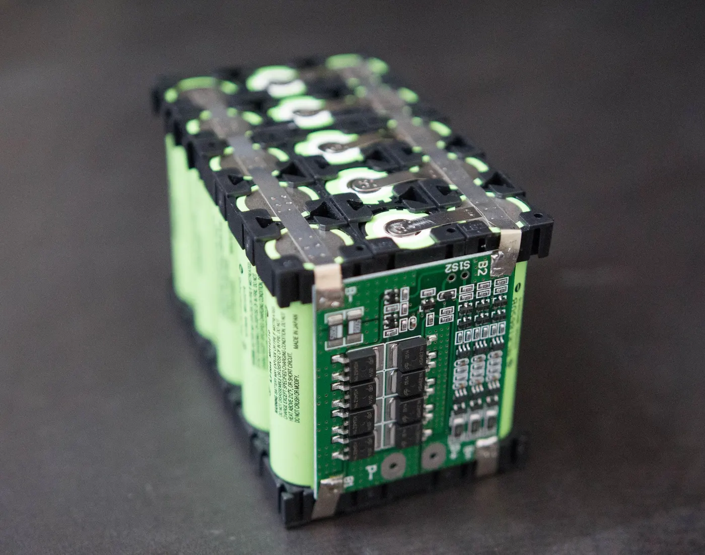
Figure (1):-Lithium Ion Battery Pack
- A rechargeable battery used in portable computer device, such as notebook computer. The most common substances used in computer battery packs are nickel cadmium (Nicad), nickel metal hydride (NiMH), and Lithium Ion.
- A new type of battery, called a smart battery, provides the computer with information about its power status so that the computer can conserve power intelligently. With a normal battery, the computer makes estimates about the battery’s condition that are not always correct.
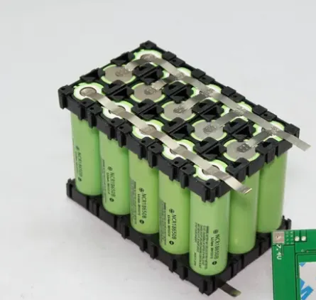
Figure (2):- Rechargeable battery pack
- Battery packs are constructed from two or more individual cells or batteries. There are two basic types of battery packs:- primary and secondary or rechargeable. Primary Batteries are disposable, non-rechargeable devices. They must be replaced once their energy supply is depleted. Secondary Batteries contain active materials that can be regenerated. When the energy produced by these industrial batteries drops below optimum efficiency, they may be recharged according to various methods, depending on the battery construction. Secondary batteries are useful in applications where frequently replacing disposable batteries is more costly, such as in electric vehicles, handheld power tools and automobile starters.
- All batteries have positive and negative terminals, marked (+) and (-) respectively, and two corresponding electrodes. The electrodes must not touch each other, and are separated by the electrolyte, which facilitates the flow of electric charge between the electrodes. A collector conducts the charge to the battery's exterior and through the load.
- When a battery is inserted into an electrical device, the device completes the circuit between the two terminals and triggers electrochemical reactions within the battery. The anode undergoes an oxidation reaction with the electrolyte and releases electrons, while the cathode undergoes a reduction reaction and absorbs the free electrons. The product of these two reactions is electricity, which is channeled out of the battery and into the device.
- When a secondary battery is recharged, its electrodes undergo an opposite process to the discharging action described above. As the battery charger passes electricity through the battery, one electrode is oxidized and produces electrons which are then absorbed by the other electrode. When the battery is fully charged, it can be connected to a load and discharged again.
Calculating state of charge:-
- SOC, or state of charge, is the equivalent of a fuel gauge for a battery. SOC cannot be determined by a simple voltage measurement, because the terminal voltage of a battery may stay substantially constant until it is completely discharged. In some types of battery, electrolyte specific gravity may be related to state of charge but this is not measurable on typical battery pack cells, and is not related to state of charge on most battery types. Most SOC methods take into account voltage and current as well as temperature and other aspects of the discharge and charge process to in essence count up or down within a pre-defined capacity of a pack. More complex state of charge estimation systems take into account the Peukert effect which relates the capacity of the battery to the discharge rate.
Advantages:-
- An advantage of a battery pack is the ease with which it can be swapped into or out of a device. This allows multiple packs to deliver extended runtimes, freeing up the device for continued use while charging the removed pack separately.
- Another advantage is the flexibility of their design and implementation, allowing the use of cheaper high-production cells or batteries to be combined into a pack for nearly any application.
- At the end of product life, batteries can be removed and recycled separately, reducing the total volume of hazardous waste.
Disadvantages:-
- Packs are often simpler for end users to repair or tamper with than a sealed non-serviceable battery or cell. Though some might consider this an advantage it is important to take safety precautions when servicing a battery pack as they pose a danger as potential chemical, electrical, and fire risks.
Battery pack capacity: 18 kWh
Cell:- ANR26650M1-B
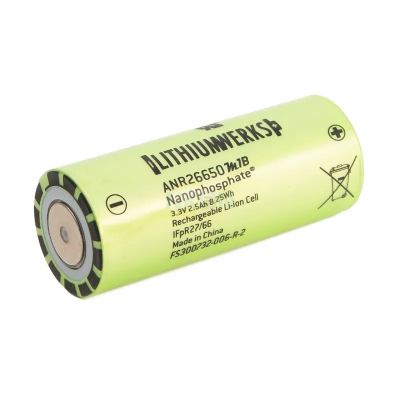
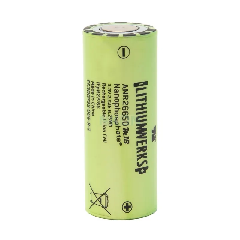
Prepare a detailed battery pack drawing along with its enclosure. State your assumptions:-
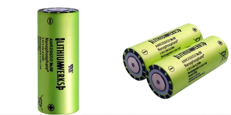
ANR26650M1-B, LithiumWerks Nanophosphate, Lithium Iron Phosphate (LiFePO4) (formerly A123), 3.3 Volts, 2.5 Ah Cylindrical Battery:-
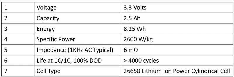
Specifications for ANR26650M1-B :-
1] Nominal Ratings:-
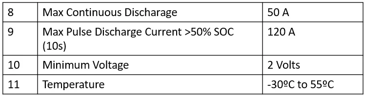
2] Discharging:-
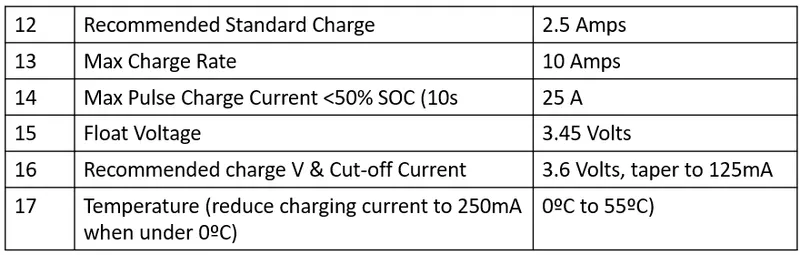
3] Charging:-
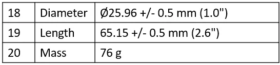
4] Mechanical:-
The Grade A cell has more information on its wrapper than the Grade B one which only is marked "ANR26650"
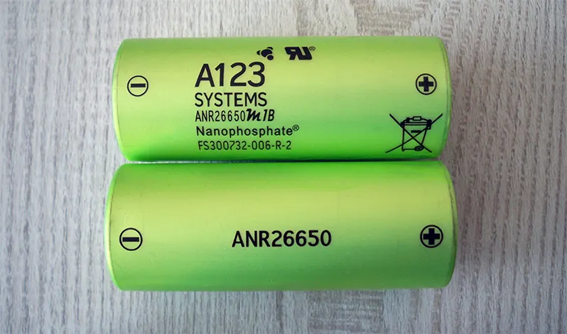
and the Grade B's negative pole has no stripes around the metal

The positive poles are identical

- The LithiumWerks ANR26650M1-B is the next generation of A123 Systems’ pioneering 26650 cylindrical cell, now with greater power and energy density and lower impedance. This versatile lithium ion cell is suitable for a wide variety of applications and system designs. Proven performance in the toughest conditions, combining durability, reliability, and safety, the ANR26650 cell offers an excellent combination of price-performance.
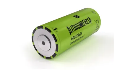
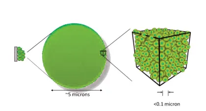
- Lithium Werks’ 26650 cells are capable of delivering very high power due to its use of patented Nanophosphate ® battery technology. Based on lithium iron phosphate chemistry (LiFePO4), the cells are inherently safe over a wide range of temperatures and conditions. Whether the application requires outstanding cycle life or stable float reliability, the Lithium Werks’ 26650 cells are suitable for a wide variety of power, pulse, or stand-by applications.
- Nanophosphate battery technology offers stable chemistry, faster charging, consistent output, excellent cycle life and superior cost performance. It provides the foundation for safe systems while meeting the most demanding customer requirements. Multiple layers of protection are employed at the chemistry, cell and system level to achieve an energy storage solution with superior safety and abuse tolerance compared to metal oxide lithium-ion chemistries.
Dimensions:-
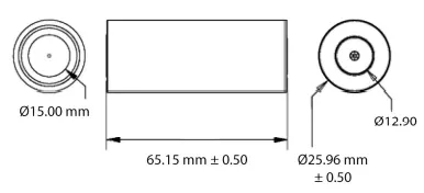
Cell Data:-
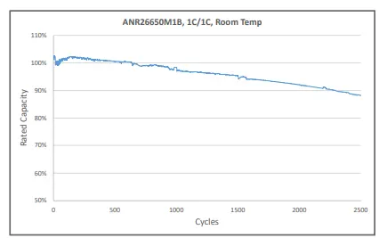
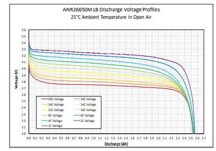
Cylindrical Cell Primary Applications:-
- Portable high power devices.
- Stationary battery backup systems.
- Grid stabilization energy storage systems.
- Commercial truck and bus hybrid electric vehicles (HEVs).
Lithium Ion Cell Benefits:-
- Power:- Over 2,600 W/kg and 5,800 W/L.
- Safety:- Excellent abuse tolerance and environmentally friendly.
- Life:- Excellent calendar life, 10X cycle life vs. conventional lithium ion.
Before designing a Battery Pack, Let's look the basic parameter of battery:-
1) Capacity:-
- The capacity of a battery or cell is defined as the amount of energy that it can deliver in a single discharge. Battery capacity is normally specified in amp-hours for larger batteries and mill-amp-hours for smaller batteries.The battery capacity may also be quoted in terms of watt-hours as this is a measure of the power it can supply, and this measure is the charge capacity in terms of amp-hours or milliamp hours times the voltage.
2) Cell Voltage:-
- Potential difference between the cell terminal.It is differentiated into Max voltage,Min voltage and Nominal voltage.Usually nominal voltage is taken for calculation and design as it is mid range between maximum and minimum voltage.
3) Charge capacity:-
- The capacity of a battery is often referred to as the charge capacity as this is the amount of charge the battery can hold. See "Capacity."
4) Charge Rate (C‐rate):-
- Charge Rate (C‐rate) is the rate of charge or discharge of a battery relative to its rated capacity. For example, a 1C rate will fully charge or discharge a battery in 1 hour. At a discharge rate of 0.5C, a battery will be fully discharged in 2 hours. The use of high C-rates typically reduces available battery capacity and can cause damage to the battery.
5) Constant-Current Charge:-
- This refers to a charging process where the level of current is maintained at a constant level regardless of the voltage of the battery or cell.
6) Constant-Voltage Charge:-
- This definition refers to a charging process in which the voltage applied to a battery is held at a constant value over the charge cycle regardless of the current drawn.
7) Cycle Life:-
- The capacity of a rechargeable cell or battery changes over its life. The definition of the battery life or cycle life of a battery is number of cycles that a cell or battery can be charged and discharged under specific conditions, before the available capacity falls to a specific performance criteria - normally 80% of the rated capacity.
- The cycle life of batteries is gaining even more in importance. Mobile phones are often replaced when their batteries come to the end of their life, and for electric cars the battery life time is of great importance as replacement of the batteries is a very expensive operation.
8) Cut-off voltage:-
- As a battery or cell is discharged it has a voltage curve that it follows - the voltage generally falling over the discharge cycle. The definition for a cell or battery of the cut-off voltage cell or battery is the voltage at which the discharge is terminated by any battery management system. This point may also be referred to as the End-of-Discharge voltage.
9) Deep Cycle:-
- A charge discharge cycle in which the discharge is continued until the battery is fully discharged. This is normally take to be the point at which it reaches its cut-off voltage, typically 80% of discharge.
10) End of Life (EoL):-
- End of Life (EoL) of a battery is reached when the battery cannot perform according to its predefined minimum specifications. EoL can be quantified in several ways:-
(i) Capacity fading is based on a given percentage drop in the battery capacity compared to its rated capacity under specified conditions.
(ii) Power fading is based on a given percentage drop in the battery’s maximum power compared to the rated power, also under specified conditions.
(iii) Energy throughput quantifies the total amount of energy a battery is expected to handle during its life, for example, 30MWh, based on specific operating conditions.
11) State of Health (SoH):-
- State of Health (SoH) of a battery measures the percentage of useful life remaining before the battery reaches EoL.
12) Rated Capacity:-
- The capacity of a battery is expressed in Ampere-hours, Ah and it is the total charge that can be obtained from a fully charged battery under specified discharge conditions. This is effectively a more exact term for the capacity of the cell or battery.
13) Self-Discharge:-
- It is found that batteries and cells will lose their charge over a period of time, and need re-charging. This self-discharge is normal, but various according to a number of variables including the technology used and the conditions. Self-discharge is defined as the recoverable loss of capacity of a cell or battery.
14) Specific Energy:-
- The gravimetric energy storage density of a battery, expressed in Watt-hours per kilogram (Wh/kg).
15) Specific Power:-
- The specific power for a battery is the gravimetric power density expressed in Watts per kilogram (W/kg).
16) State of Charge:-
- State of charge (SoC) is the level of charge of an electric battery relative to its capacity. The units of SoC are percentage points (0% = empty; 100% = full). An alternative form of the same measure is the depth of discharge(DOD), the inverse of SoC (100% = empty; 0% = full).
17) Depth of Discharge(DOD):-
- A battery’s depth of discharge (DoD) indicates the percentage of the battery that has been discharged relative to the overall capacity of the battery. Depth of Discharge is defined as the capacity that is discharged from a fully charged battery, divided by battery nominal capacity. Depth of discharge is normally expressed as a percentage.
Battery capacity basics:-
- Most frequently the capacity of a battery is measured in terms of the actual charge that it stores. It relates to the current that it can supply and for how long.
- As we all know, batteries only last for a certain time, and it often seems that they run out of charge at the most inconvenient moment, however by understanding a little more about battery capacity and battery life it can be possible to plan their usage a little better.
- The capacity of a battery, whether rechargeable or non-rechargeable is most commonly measured in amp hours or milliamp hours.
- Typically amp hours are used for much larger items such as car batteries or many other electrical items where the current is measured in amps, the units will be amp-hours, whereas for smaller items like batteries used for powering electronic equipment, the capacity is typically measured in milliamp-hours.
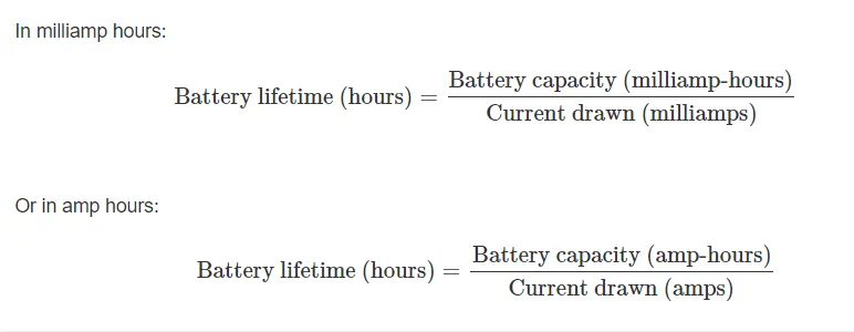
Battery capacity in terms of Wh:-
- Another way of looking at the capacity of a battery is to look at the power it can provide. In other words it looks at the voltage as well as the current it can provide.
- Essentially using watt hours provides the power capacity for the battery. The power capacity defines how much energy is stored in the battery.
- In terms of a definition, a Watt hour can be determined by multiplying battery voltage by the amount of current the battery delivers over the time before it becomes discharged.
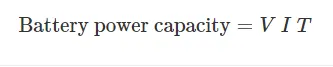
Where:-
V = voltage in volts
I = current in amps
T = time for which current flows before battery is exhausted.
Calculation for 18 KWh battery pack:-
Calculation for Vehicle Parameter:-
Maximum speed to be achived (m/s)-
1] `V=100 (Km)/(hr)` Assumed
`V=100*0.278`
`V=27.8 m/s`
2] Vehicle Mass (Kg)-
`M=Mv+Mp`
`M=1000+200`
`=1200 Kg`
Where,
Mv = Vehicle Mass
Mp = Weight of Passenger
3] Let calculate Rolling/ Friction Force-
Rolling Force(N)-
`Fr=Cr*m*g`
Where,
Cr = Coefficient of rolling resistance. (Cr value from 0.01 to 0.02 for cars on asphalt)
Cr = 0.015 Assume
g = Acceleration due to gravity = 9.81
`Fr=Cr*m*g`
`=0.015*1200*9.81`
`Fr= 176.58 N`
4] Now, we calculate the Drag force (N)-
`Fd=0.5*Cd*Af*d*V^2`
Where,
Cd = Drag Coefficient
Cd = 0.2 to 0.3 for cars = 0.25 Assume
d = Fluid density = 1.2 Kg/m^3 (Air)
Af = Frontal area of car = 2.2 m^2 Assumed.
`Fd=0.5*0.25*2.2*1.2*27.8^2`
`= 255.0372 N`
5] Net Force and Power required for vehicle-
`Ft=Fr+Fd`
`=176.58+255.0372`
`Ft=431.62N`
6] Calculation Power required for Vehicle-
`P=Ft*V`
`=431.62*27.8`
`=11999.036 W`
`P=11.99`
`P=12Kw`
7] Calculate the Energy used-
`E=P*T`
`T=D/V`
Where,
D= Range or distance covered
D= 250 Km Assumed.
T= Time required to cover that distance.
`T=250/100`
`=2.5 hr`
`E=12*2.5`
`=30kWh`
For our example we will consider Cylindrical Lithium-Ion Cells-
Chemistry- Namophosphate Higt Power Lithium-Ion Cell ANR26650M1-B as shown below-
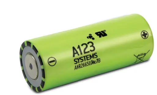
Figure(3):- Cylindrical Lithium-Ion Cells
Cell Parameter-
Cell Dimension = `phi26*65`
Where, Diameter of Single cell = 26 mm= 0.026m
Length of Single cell = 65mm= 0.065m
Cell Capacity (Nominal/Minimum [0.5C Rate]) = 2.5/2.4 Ah
Nominal Voltage of Single cell = 3.3 V
Mass of Single Cell = 76 g = 0.076 (1 gram= 0.001 Kilogram)
Maximum Continuous Discharge = 50 A
Maximum pulse Continuous Discharge (10 Sec) = 120 A
Mathemathical calculation for battery Pack:-
Cc = Cell Capacity = 2.5 Amper-hr
Vc = Cell Voltage = 3.3 V
Selecting Voltage for our Battery Pack-
Battery Pack Calculation:-
1] Cb = Battery Capacity
`Cb=E/(Vb)`
`= 30000/150`
`Cb=200 Ahr`
2] Now, Find the value of Watt:-
Voltage = 3.3 V
Ampere = 2.5 Ahr
Watt = `3.3*2.5`
= `8.25 Whr`
3] Calculation of Volume of Single cell:-
`Vcell = pir^2h`
`=3.14*0.013^2*0.065`
`=0.0345m^3`
4] Calculation of Energy Density for Single cell:-
Volumetric energy = Single cell energy / Vcell
`=8.25/0.0345`
`= 239.13 (Wh)/(m^3)`
Gravimetric energy = Single cell energy / Single cell mass
`=8.25/0.076`
`=108.55 (Wh)/(Kg)`
Now, We calculate the Total No of cell required for the EV Battery Pack:-
Let assume Nominal Voltage for series connection=150, This depends upon the motor power.
5] Calculate the no of cell in Series Combination-
`Sc=(150)/(Vc)`
`=150/3.3`
`Sc= 46 Cells`
Where,
Ct = Total no of Cells
Sc = Cell in Serier Combination
Pc = Cell in Parallel Combination
6] Calculate the no of cell in Parallel Combination-
`Pc=(Cb)/(Cc)`
`= 122.22/2.5`
`Pc=49 Cells`
7] Calculate the Total no of cells:-
`Ct=Sc*Pc`
`= 46*49`
`Ct= 2254 Cell`
8] Calculate the Voltage of Each module-
(i) The Voltage of the module is the product of the number of cell arranged in series and Nominal voltage of each cell induvidual cell.
Voltage of each module = Number of cells in series*Single cell Voltage
`=46*3.3`
`=151.8 V`
Capacity of each module= Number of cells in Parallel*Nominal cell capacity
`=2.5*49`
`=122.5 Ah`
(ii) Energy = Voltage * Capacity
`=151.8*122.5`
`=18.6 kWh`
9] The total energy per modul is obtaine from the product of the cell capacity, the total voltage of the module and the number of cell arranged in parallel-
Total Energy per module = `3.3*46*49`
`= 7.4382Kwh`
10] Calculate Volume of our Battery pack:-
Volume of Battery Pack = Vcell *Ct
`=0.0349*2254`
`=78.664 m^3`
11] Mass of Battery pack:-
Total Mass of Battery pack = Total No. of cell (Ct) * Mass of Single Lithium Ion cell
= 2254*0.076
= 171.304 Kg
12] Calculate of high Voltage Battery Pack:-
For design of the battery pack, Here we assume a vehicle 200 Km in 18000Wh Battery Pack-
We will calculate per Km average-
Energy `=18600/200`
`=93(Wh)/(Km)`
13] Calculate Maximum Current of battery pack:-
Cmbp = Our Battery Pack Capacity/ 150
`=18600/150`
`=124 Ahr`
The above we have calculate the Battery Pack of Lithium Ion Cell for Battery Elctric Vehicle(BEV).
Cylindrical Lithium Batteries:-
- Cylindrical lithium batteries, as the name suggests, feature electrodes that are encased in a cylindrical cell that is wound very tightly within a specially designed metal casing. This unique makeup helps to minimize the chances that the electrode material inside will break up, even under the heaviest of use conditions.
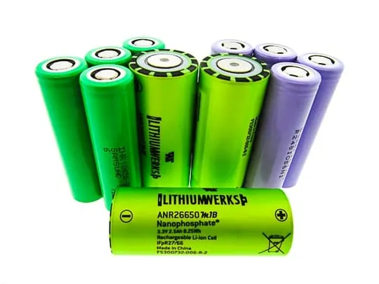
Figure (4):- Cylindrical Lithium Batteries
- Mechanical vibrations, thermal cycling from charging and discharging, and the mechanical expansion of current conductors are all things that can affect a battery's lifespan. Therefore, the design of these cylindrical units is intended to help mitigate risk from these and other factors as much as possible.
- On the inside of a cylindrical battery, a series of cells are combined and operate in parallel to one another. This is done to help increase both the voltage and the overall capacity of the battery pack.
- For these reasons, cylindrical batteries are usually the kind that are found in the a forementioned Medical Device System. Smaller, more specially designed cylindrical cells are also commonly found in portable devices like laptop computers. Notably, Tesla also made headlines recently by selecting cylindrical lithium batteries to power its fleet of popular electric cars.
Battery packs are designed by connecting multiple cells in series; each cell adds its voltage to the battery’s terminal voltage. Figure (5) below shows a typical EarthX 13.2V LiFePO4 starter battery cell configuration.

Figure (5):- multiple cells connecting in series
Batteries may consist of a combination of series and parallel connections. Cells in parallel increased current handling; each cell adds to the ampere-hour (Ah) total of the battery.an example of a series and parallel configuration.13.2V / 12.4A
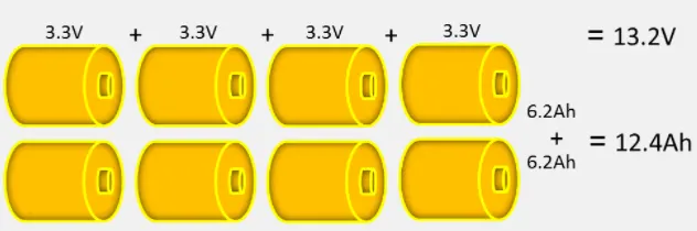
Figure (6):- combination of series and parallel connections
Parallel Operation:-
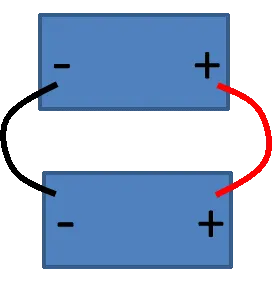
- Like individual cells, you can combine batteries together in parallel to achieve higher energy/power (amp-hours, amps). Up to two batteries can be put in parallel. To combine batteries in parallel, connect positive to positive and negative to negative as shown in Figure (7).
- Our batteries can be connected in series to increase the operating voltages. Two batteries can be used in series with a nominal system voltage of 26.4V (a single battery’s voltage is 13.2V). See the example below for series wiring Figure (8).

Figure (8):-Series Operation
Series / Parallel Operation:-
- Below is the approved series and parallel configuration Figure (9) series are wired as two separate series battery paths, meaning there is no cross ties between the centers of the two separate paths. Figure (9) shows an incorrect connection with a cross tie between the centers of the two separate series paths.

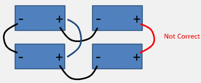
Figure (9):- Series / Parallel Operation
Voltages and Capacity:-
- Cells can be combined together either in series or in parallel to achieve higher operating voltages and capacities, respectively.
Series Strings:-
- Cells combined in series strings can achieve higher operating voltages by connecting the positive terminal of one cell to the negative terminal of the next cell. Connect strings of series cells using their current collection tabs in a manner similar to that illustrated in Figure 4.
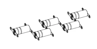
Figure (10):- Cells Connected in Series
- Two cells in series: 2 x 3.3V = 6.6V (nominal)
- Three cells in series: 3 x 3.3V = 9.9V (nominal)
Parallel Strings:-
- Cells combined in parallel strings can achieve higher operating capacities by connecting like-polarity terminals of adjacent cells to each other. Connect strings of parallel cells using their current collection tabs in a manner similar to that illustrated in Figure 5.
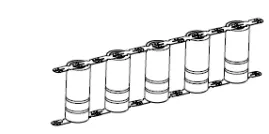
Figure (11):- Cells Connected in Parallel
- Two cells in parallel: 2 x 2.5Ah = 5Ah (nominal for 26650 cells)
- Three cells in parallel: 3 x 2.5Ah = 7.5Ah (nominal for 26650 cells)
Mechanical Connection and Protection:-
- Design mechanical interconnects to prevent accidental short circuits. Size these mechanical interconnects to carry the expected maximum rated current for both the maximum time and ambient temperature in which the pack is expected to operate.
Cell Interconnects:-
- Size cell interconnects for the expected maximum current carrying capability. Improperly sized tabs could heat up excessively, resulting in even higher resistivity. For reliable welded connections at the terminals, A123 Systems recommends either pure nickel tabs or nickel-clad copper tabs. In addition, other alloys afford both the weldability, strength and low resistance, which are all desirable features of a good interconnection. Cell interconnects (tabs) should be neither soldered on the end caps nor attached using extreme heat. A123 Systems recommends tabs be resistance or laser-welded to both ends of the cells. Resistance welding provides a constant current for a specified period of time through a salient feature in the weld tab. These parameters can be specified and regulated for a consistent high-quality weld every time.
Nickel Strips:-
- Nickel strip is commonly used in battery building due to its ease of use in spot welding and soldering as well its high corrosion resistance over time. Nickel is magnetic at or near room temperature.
- It is because the conductivity and effectiveness of nickel depend heavily on its purity. However, there is a small amount of impurity that may get into the product while casting it. To avoid this, we try to maintain the lowest temperature that prevents the impurities from getting into the material.
- Nickel strips are used as the battery connectors because they have 20-30% more conductivity than other materials. The manufactures look for high conductivity because it allows them to produce batteries in different sizes and shapes. That too, without worrying about the capabilities of the battery to handle power and heat.
- This product directly from raw materials of high purity nickel plate rolling, more than 99.96% of nickel content, with a guarantee of high purity nickel, low-resistance (15% lower than the traditional process so), to avoid the traditional craft materials in the smelting process of adding resulting decrease of nickel with purity, resistance increases the defect, this method does not change the chemical composition of energy nickel plate.
Pure nickel tape / sheet (nickel purity above 99.96%):-
1] With Good gloss, ductility and weldability.
2] No peeling, no spots, no oxidation, no scratches.
Figure (12):- Nickel Strips
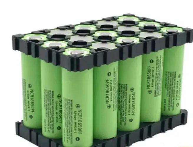
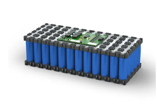
Cell Holder For Lithium-ion Battery:-
- A battery holder is one or more compartments or chambers for holding a battery. For dry cells, the holder must also make electrical contact with the battery terminals. For wet cells, cables are often connected to the battery terminals, as is found in automobiles or emergency lighting equipment.

Battery Pack Process:-
- The lithium battery pack consists of cylindrical cells, battery protection board, connecting nickel sheet, leading out nickel sheet, green paper accessories, insulating paper, wire or plug wire, PVC outer package or shell, output (including connector), key switch, power indicator, EVA, highland barley paper, plastic support and other auxiliary materials
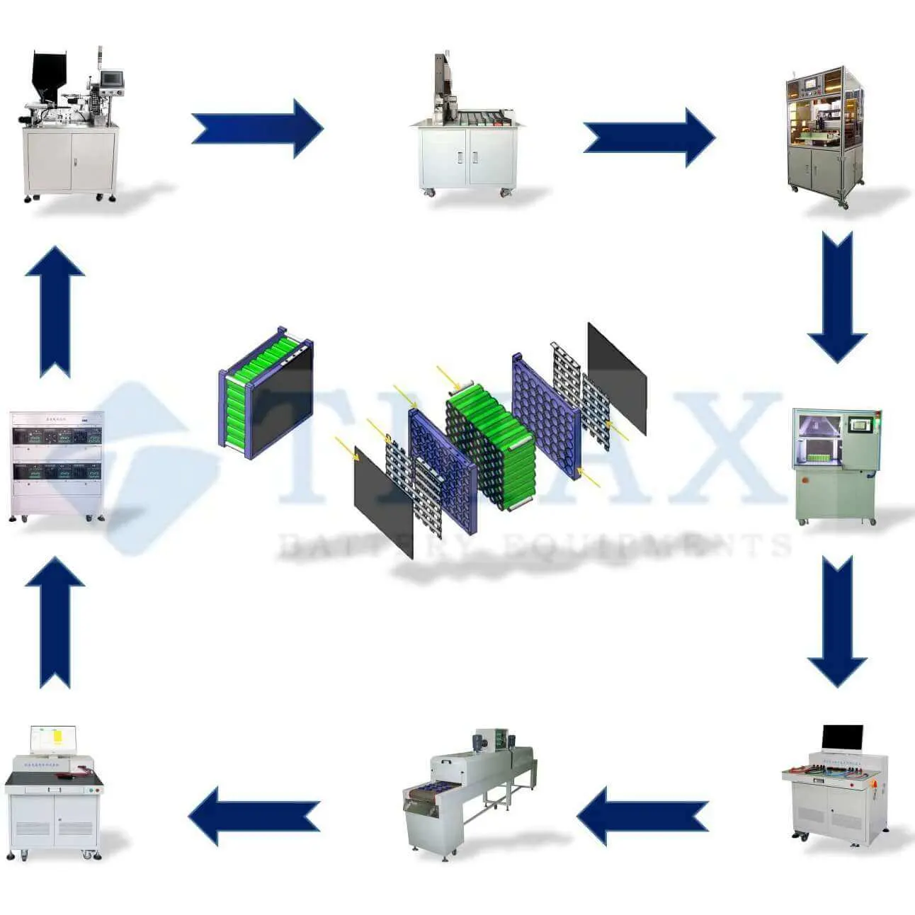
Figure (13):-Battery Pack Process
Battery pack assembly:-
- Depending on the overall dimensions of the vehicle as well as its power and energy requirements, there are different battery configurations with different degrees of complexity. The most basic battery pack
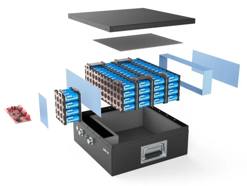
simply has a series of cells arranged in series plus a battery management system or controller (BMS or BMC), plus some safety and connection elements. All these elements are confined within a metallic receptacle that serves as an impact protector and fixing container. - A typical energy storage system is shown in figure 2, indicating some main components. On the left hand, a complete electric vehicle battery pack exploded diagram is shown including the names of the main component. Then, on the right hand, an electric vehicle battery module is shown indicating the names of the components. It should be noted that a battery pack is made up of several interconnected modules, while a battery module is made up of several interconnected cells.
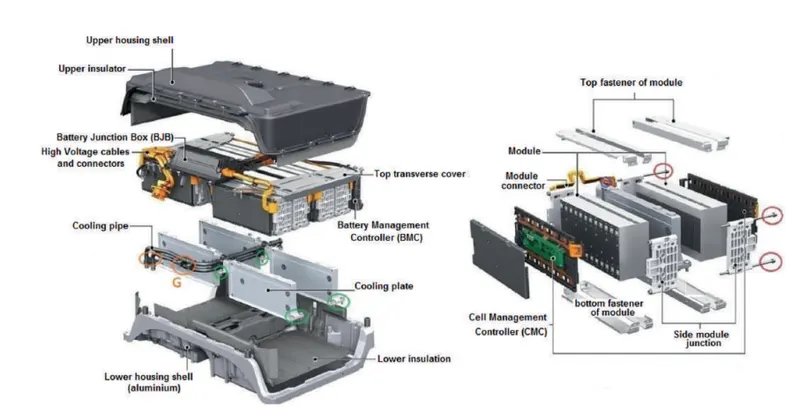
Figure(14):- Battery pack assembly
PRODUCTION PROCESSES:-
- Battery production starts with the preparation of raw materials, like the Li-metaloxides and graphite, which have to be thoroughly ground, mixed and conditioned. Together with solvents they form a slurry of active material.
- Second step is the electrode production, which involves coating of the active material slurry on top of metal sheets in a roll-to-roll process, followed by drying and compactation (called calendering).
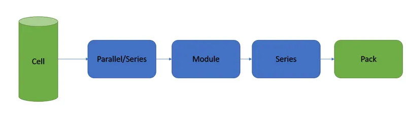
The next step is the cell production. Slitting, separation, stacking or winding, contacting of the electrochemical cell units, packaging are the single processes employed here. Formation (initial charging) and ageing are important, but time consuming steps (24 hours and up to a month, respectively) to finalize cell production. - The last step in battery production is the module and pack assembly. Important overall processes are inspection and test, clean room and dry room technologies, line integration and automation.
The production of Li-ion batteries for high-power applications today is basically low volume manufacture. Producers work hard on increasing yields, reliability and process stability. However, inspection and test for all critical process steps are often missing. A continous in-line operation is not realised yet, mostly in cell production, due to roll-to-roll processing.
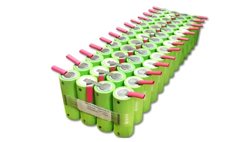
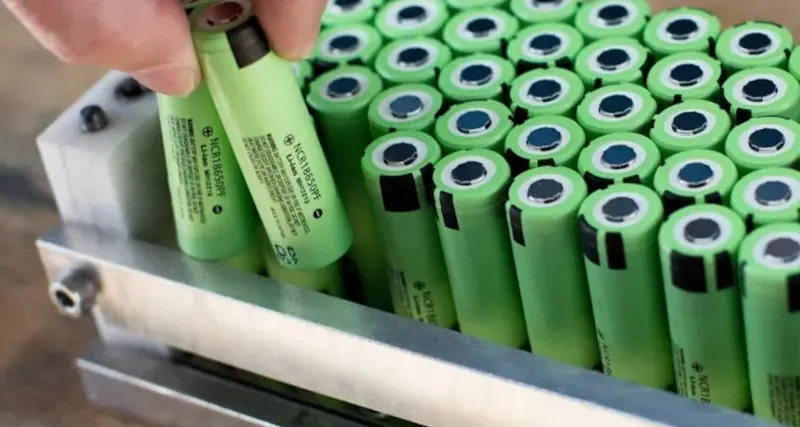
Process Characteristics:-
1] Adopt qualified lithium battery
2] Low internal resistance and good consistency
3] The structure of the battery adopts ventilation design, and the space between the two adjacent batteries is not less than 2mm. This structure requires the use of plastic bracket to fix the battery.
4] Pack battery factory uses slotted nickel strips in spot welding, the size of nickel strip meets the requirements of high current discharge, the nickel strip material ensures low internal resistance, the spot welding machine ensures stable operation, and the welding needle ensures quality.
5] Different batches of batteries are made into typical finished products and life tests are carried out. When the experience of lithium battery pack design specification is summarized, the battery finished products are tested to get the actual cycle life.
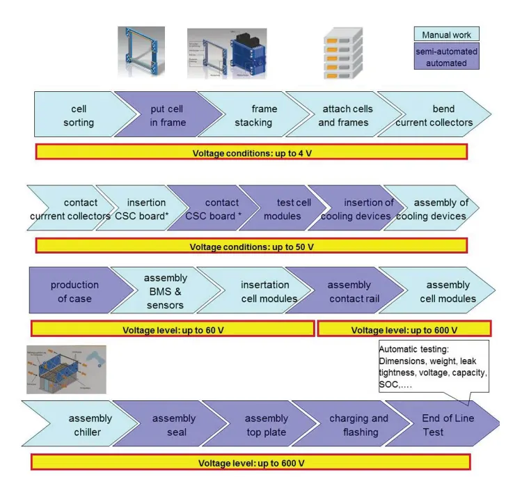
Figure (15):- Typical module and pack assembly
Detailed Process Cylindrical Battery Pack Assembly:-
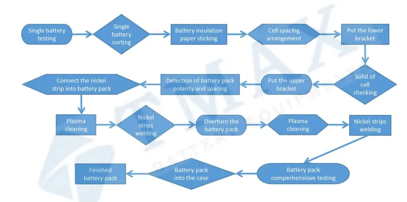
Figure (16):- Flow Chart for Process Cylindrical Battery Pack Assembly
Refurbishing process:-
- An electric vehicle battery pack traces a cycle or path that consists of the following steps. First of all, it is manufactured by a battery assembler under the requirements of the vehicle manufacturer (OEM).
The OEM requirements will be established in terms of power (kW), storage capacity (kWh), dimensions and fixing points, control and communication with the on-board computer, as well as type of connectors. - Secondly, the battery pack is installed by the OEM in the electric vehicle where it is used until it reaches a State of Health (SoH) of between 70% and 80% of its initial value, depending on the manufacturer’s
specifications. At this point, the battery pack has reached the End of Life (EoL), where decisions regarding further steps need to be taken.
Diagnosis & Classification:-
- Before starting the refurbishing process, it is necessary to perform a diagnosis and classification, in order to determine if the battery pack can be repurposed, remanufactured or recycled. This result of the assessment depends on the degree of aging, degradation or damage. Extensive information originated during the battery automotive life is crucial in order to make an early diagnosis and an easier classification.
After the diagnosis, the classification depends on several factors such as the SOH, the remaining useful life (RUL), the safety conditions and specific costs of reparation. A complexity analysis that includes all those factors is made in order to define the way to follow. After classification, the refurbishing process takes place. It is composed of the following steps:-
1) Screening
2) Disassembly
3) Repair (cellreplacement & refit)
4) Reassembly and 5) Testing, before a new installation for another application. The whole process is shown in figure (17).
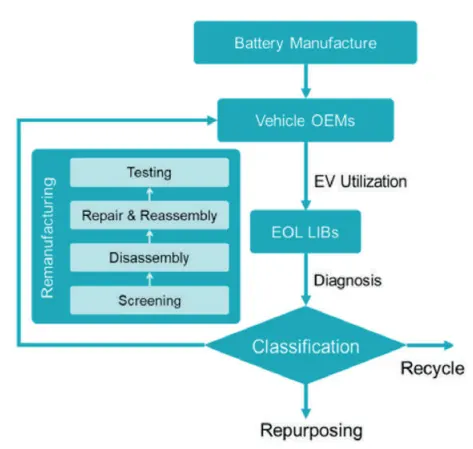
Figure (17):- Refurbishing flowchart
1] Screening:-
- The screening step in a refurbishing process is carried out in order to identify the damaged or degraded cells inside an EV battery pack. The process can be performed by using the on-board computer´s information. The BMS of the EV could provide critical information in order to determine the SoH of each cell. Testing the battery pack is another option to make the same determination, discarding useless cells.
2] Disassembly:-
- As it was shown before, the structure of the battery systems can be very complex. In the disassembly process, the battery system is dismantled at module or cell level. The disassembly step includes opening the battery framework, removing the electrical and mechanical connections between the components, as well as removing auxiliary electronic parts. Currently, a standard for lithium ion cells and battery packs does not exist; the disassembly of an EVB needs to be handled manually. Due to the high voltage, the disassembly process is dangerous, requiring skilled technicians and specialized equipment. Robotic battery disassembly could decrease the risk of human injury and reduce production costs.
3] Cell replacement & refit:-
- The repair stage in the refurbishing process is one of the critical phases in order to obtain a good refurbished product. One of the first steps is to replace cells that have been identified as defective, both by analysing the historical data or by testing modules and/or cells once the pack has been opened.
- Another important step in the repair step is the verification and refit of the entire electrical circuit, including power cables, control wiring and connectors. Likewise, the BMS at the battery pack level or at the module level must be tested and verified in such a way that its correct operation is ensured to avoid future failures.
- At this stage, it is important to ensure that all installed cells have identical operating characteristics to ensure that their operation is within a safe range, avoiding undervoltages and overvoltages. Programming or reprogramming of the BMS must be done in order to ensure a safe operation.
4] Reassembly:-
- The reassembly process is very similar to the disassembly step if the remanufactured packs are used for the same purpose. If not, a new design must be carried out to be able to build a new battery pack. The same concept applies to the original battery management system (BMS), thermal management system (TMS), and equalization management system (EMS). They do not need additional modifications if the remanufactured packs are used for the same purpose but a new design must be done to build a new battery pack.
5] Testing:-
- Final tests must be carried out in order to verify that the performance of the battery pack is satisfactory. For this, certain standards must be met in such a way that the test step is adequately validated by the repair agent. Certain external validation (of the process or of the product) and certifications may eventually be required.
Safety of The Battery Pack:-
- Proper handling and battery pack design must be followed to make sure the A123 Systems Nanophosphate cells operate safely. These cells can store significant amounts of energy, and (unlike most other types of cells) deliver this energy very quickly. Appropriate pack design must provide sufficient mechanical and environmental protection to ensure the cells operate within the proper voltage, current, and temperature limits.
- Secondary (rechargeable) lithium batteries are comprised of rechargeable cells containing an intercalated lithium compound for the anode and cathode. Rechargeable lithium batteries are commonly referred to as “lithium-ion” batteries.
- Single lithium-ion batteries (also referred to as cells) have an operating voltage (V) that ranges from 3.6–4.2V. Lithium ions move from the anode to the cathode during discharge. The ions reverse direction during charging. The lithiated metal oxide or phosphate coating on the cathode defines the “chemistry” of the battery.
Lithium-ion batteries have electrolytes that are typically a mixture of organic carbonates such as ethylene carbonate or diethyl carbonate. The flammability characteristics (flashpoint) of common carbonates used in lithium-ion batteries vary from 18 to 145 degrees C. - The use of rechargeable lithium-ion batteries in consumer products is very common and they are generally considered safe to use. But as with any energy storage device they carry safety risks including overheating, fires and explosions. Lithium-ion batteries are more susceptible to being damaged than other types of batteries and can become hazardous in certain conditions. Take precautions when using, charging and storing these batteries.
- Once the battery pack design is over, the safety of the battery pack must be ensured.The batteries operate at high energies.Thus they are prone to catching fire easily if proper safety measures are not taken.One of the most common safety device used is a fuse.It break open when excess current passes throuth it.Some fuses reset once the temperature goes down the maximum limit while others make the batteries completely useless once the open.A switch is used in wired networks to connect to other devices using ethernet cable, the switch allows each connected device to talk to the others. Wireless only networks do not use switches because devices such as wireless router and adapters communicate directly with one another.In electronics and electrical engineering, a fuse is an electrical safety device that operates to provide over current protection of an electrical circuit. Its essential component is a metal wire or strip that melts when too much current flows through it, thereby stopping or interrupting the current. Positive Thermal Coefficient (PTC) is one such device which resets once the temperature is below the threshold limit.
Result:-
The Detailed Specification of the Cell:- ANR26650M1-B as shown below:-
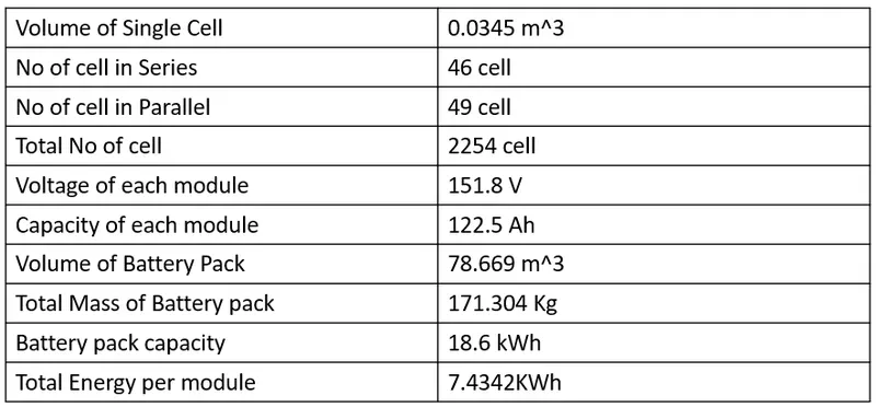
Conclusion:-
- Design of the Battery Pack of an Electric Vehicle.It fulfills all the requirements of the Battery Electric Vehicle.The Safety parameters of the Battery Pack have also been discussed above.
Referance Links:-
3) https://www.buya123products.com/uploads/vipcase/c9dec23d34292dd9e30058723737edee.pdf
4) https://www.master-instruments.com.au/products/62294/ANR26650M1B.html