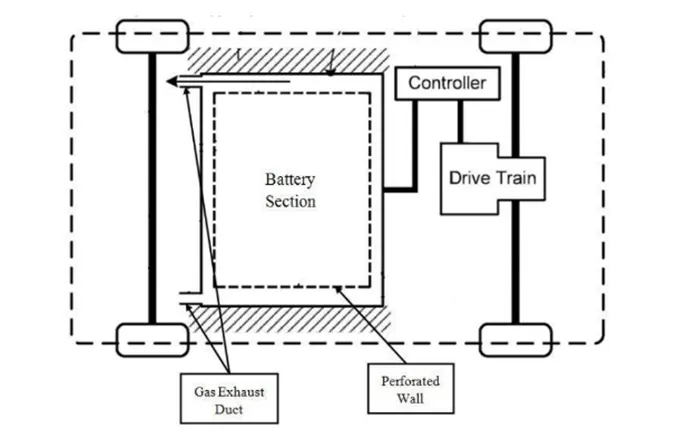
Project 1 Mechanical design of battery pack
In order to design a Baterypack, Cells have to chosen, assembled as Modules. The Modules will thene integrated to achieve the needed
power requirements.
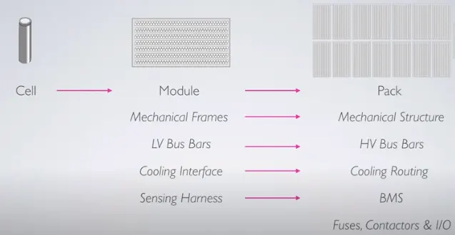
Basic Calculations:
Based on the given Data Cell ANR26650M1-B has been chosen:
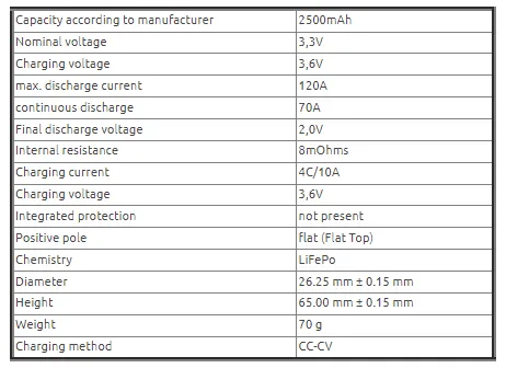
From the data:
Energy from Single Cell = Nominal Voltage * Nomianl Capacity
= 3.6*2.5 = 8.25Wh
We know,
Usable Pack size: KWh x 0.80 x Peukerts Coefficient = Usable KWh
Peukerts Coefficient for LiFePO4 = 1.0
Usable Pack size = 18/0.8 = 22.5Kwh
Let us assume required max Voltage is 330 Volts
Number of cells required = maximum Voltage/Nominal Voltage = 330/3.3 =100 cells
100 Cells need to be connected in Series
Energy from 100 Cells connected in Series (1Module) = 100*8.25 = 0.825KWh
Number of Modules required = Total Energy/Energy from one Module = 22.5/.825 = 28
28 Modules should be connected in Parallel so that Maximum Voltage remains constant and required Energy is obtained.
Hence the configuration of the Battery pack is 100s28p.
Overall capacity(Ah) of Battery pack = 28*2.5 = 70Ah
Modul level:
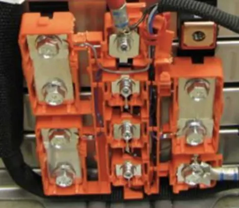
LV Bus Bars:
A busbar is a metallic strip or bar, typically housed inside switchgear, panel boards, and busway enclosures for local high current power distribution. They can also act as fuses to prevent short circuits.
Cooling Interface:
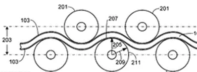
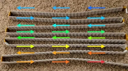
The cooling manifold assembly includes a coolant tube that is interposed between the first row of cells and the second row of cells, where the first and second rows of cells are adjacent and preferably offset from one another. A thermal interface layer is attached to the cooling tube, the thermal interface layer includes a plurality of pliable fingers that extend away from the cooling tube and are interposed between the cooling tube and the first row of cells, and interposed between the cooling tube and the second row of cells, where the pliable fingers are deflected by, and in thermal contact with, the cells of the first and second rows of cells.
Sensing Harness:
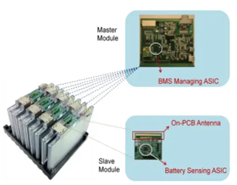
PCM or PCB ( protection circuit module or board ) will protect the Lithium battery pack from overcharging, over-discharging and over-drain, therefore it is a must to have to avoid Lithium battery pack from explosion, fire, and damage. Normally a single master module and multiple slave modules are mounted on battery cells. The slave module has embedded sensors that measure various physical characteristics such as voltage, current, and temperature of the battery cell. The control commands and responses are delivered wirelessly between the master and slave BMS modules. No wire-harness is involved.
Mechanical Frames:
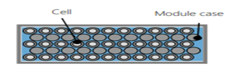
In the architecture of a round cell module, the cells are fixed by the module case. The space between the cells can be used by a cooling system or direct cooling. The metal housing prevents the cell from swelling. At the module level, the cells can be connected both serial and parallel. The cells are contacted via a metal plate on both sides.
Pack level:
HV Busbars:
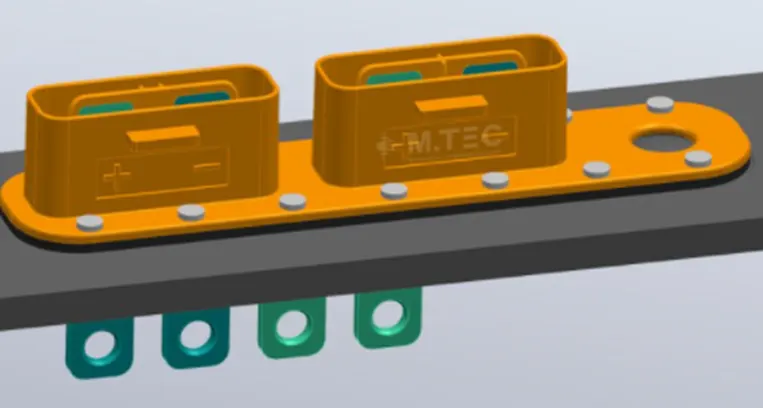
The over-molded busbar is used to safely conduct the electrical current between the high-voltage accumulator, control unit, drive and charging unit.
Cooling routing:
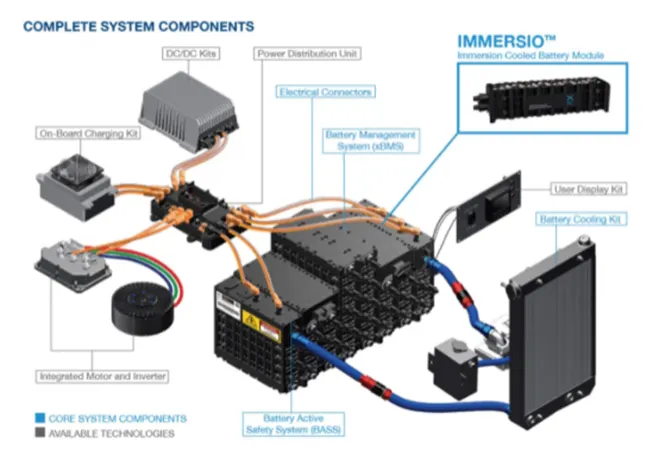
Immersion cooling involves submerging the battery cells in a liquid coolant, in doing so superior thermal contact and homogeneity can be achieved. Additionally, the flame-retardant nature of the fluids acts as a safety feature, suppressing thermal runaway events before they propagate between cells.
Battery Management System:
The main functions of a Battery Management System for electric vehicles are:
- Battery protection in order to prevent operations outside its safe operating area.
- Battery monitoring by estimating the battery pack state of charge (SoC) and state of health (SoH) during charging and discharging.
- Battery optimization thanks to cell balancing improves the battery life and capacity.
Mechanical Structure:
Basically forms the Underbodypanel of the vehicle.