Project 1 : Flow over Ahmed Body
Aim : To simulate the ahmed body with slant height 25 and 35 degrees for drag and lift coefficient with velocity profile at different distances from inlet of the wind tunnel.
Workflow:
- Make a ahmed body with different slant height according to the sketch
- Make a wind tunnel around the ahmed body.
- Make mesh with half of the body and name the plane as symmetry plane
- Assign part to regions with different named selections as inlet,outlet,symmetry plane.
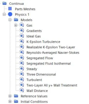
- Select turbulence model with y+ of 10 and model as k-epsilon realizable model
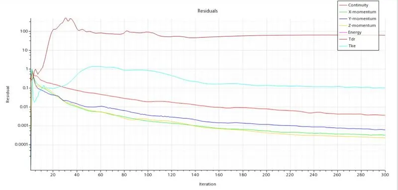
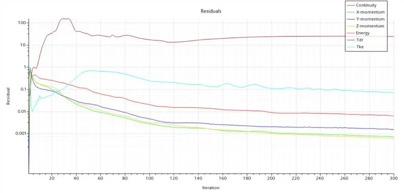
- Run steady state simulation for around 300 iterations
- Post process the results for drag ,lift and velocity profile
Geometry:
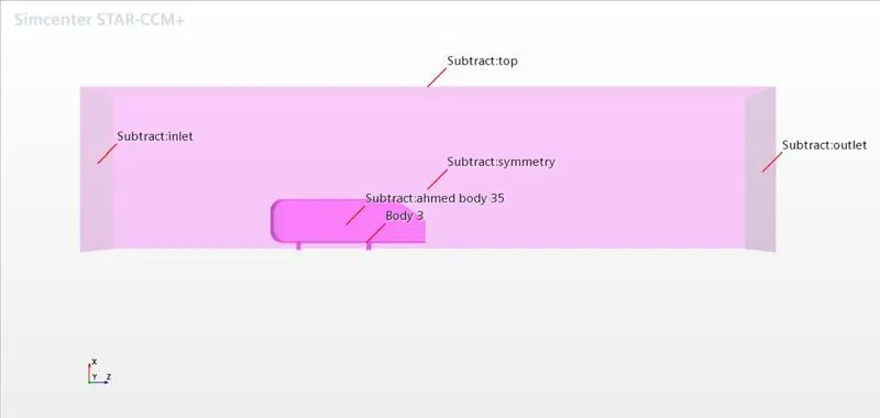
Make geometry for slant height 25 degrees with different selections for inlet, outlet ,symmetry with wind tunnel
Mesh:
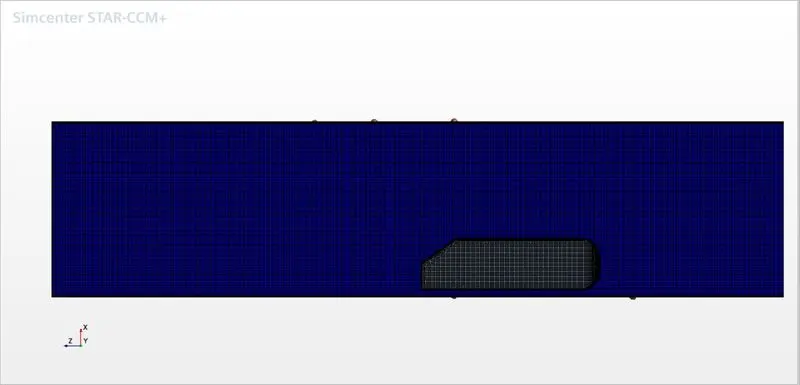
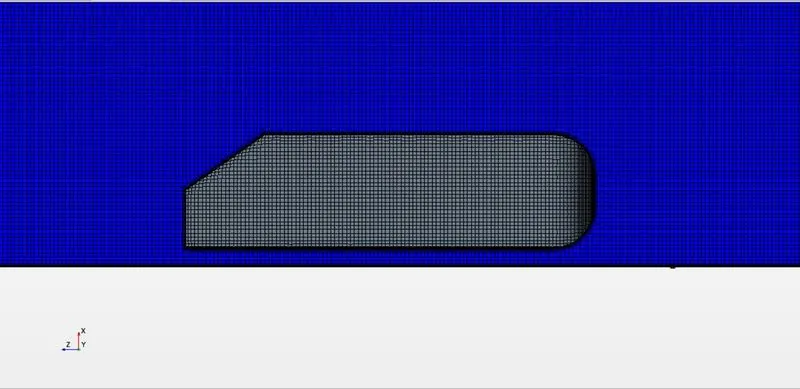
Base size : 0.05 m
Target surface size: 0.01 m
No of prism layers: 12
Prism layer stretch factor: 1.5
prism layer total thickness : 10mm
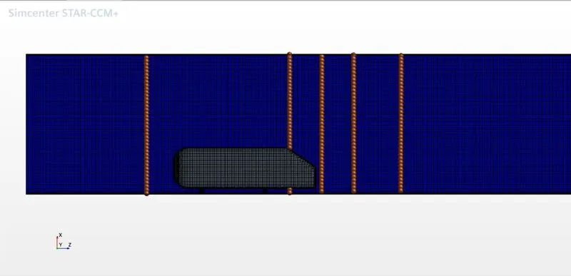
Velocity line probes at different places:
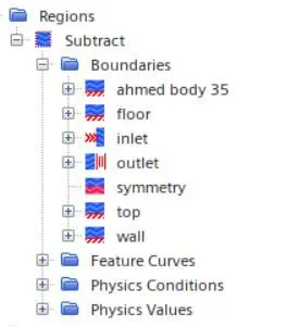
Regions:
Assign parts to regions:
Physics model:
The y+ of 10 is chosen with velocity of 25 m/s
The total prism layer thickness of 10 mm is taken for total 12 layers
k-epsilon reliazable is chosen as the results shows considerable convergence.
Results for slant angle of 25 degrees:
Residuals:
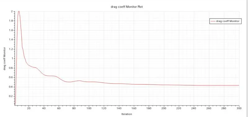
Drag coefficient:
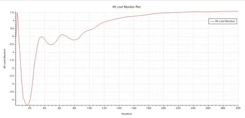
Lift coefficient:
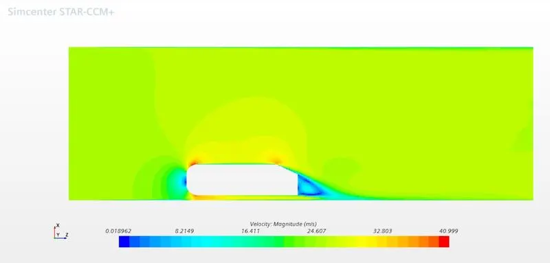
Velocity contour:
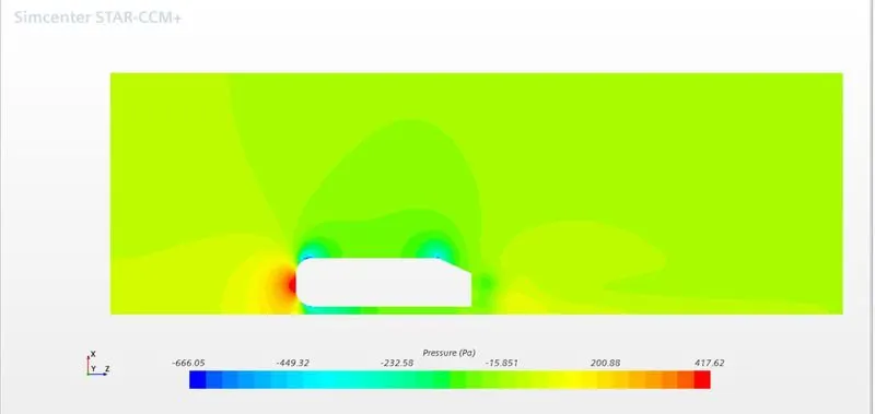
Pressure contour:
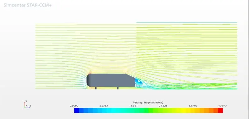
Velocity streamlines:
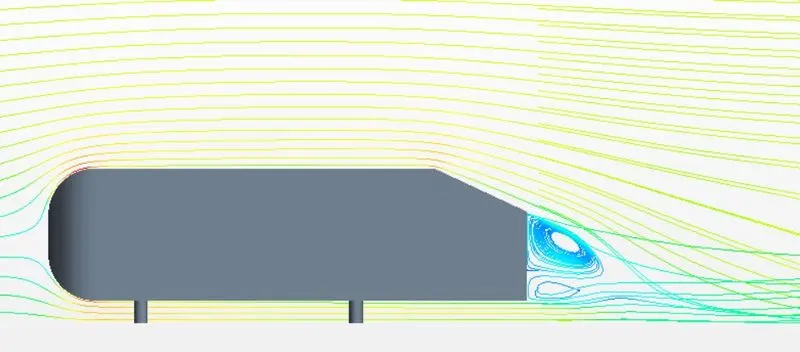
Velocity streamlines in wake region:
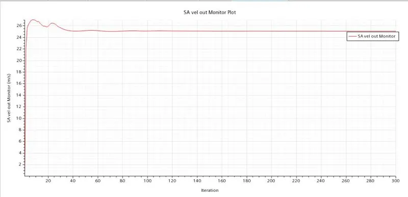
Velocity at outlet:
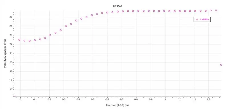
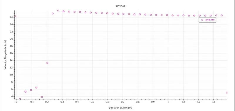
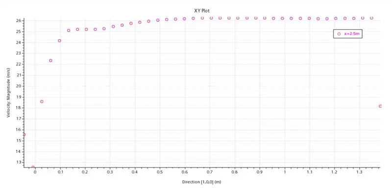
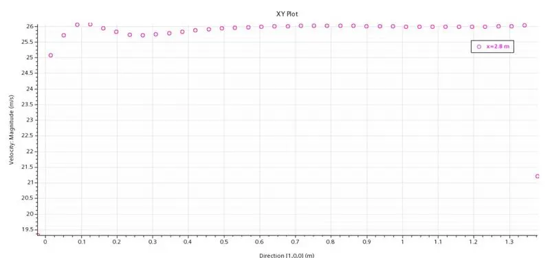
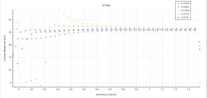
Velocity probes at different distances from start :
At x=0.8m
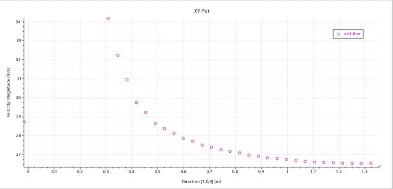
At x=1.8 m
At x=2.1 m:
At x=2.5 m
At x=2.8 m
All velocity line probes:
Drag coeff value:

Lift coeff value:

---------------------------------------------------------------------------------Results for slant angle of 35 degrees:----------------------------------------------------------------------------------
Residuals:
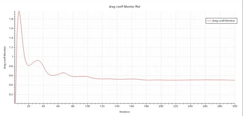
Drag coefficient:
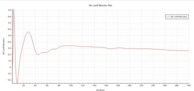
Lift coeffiecient:
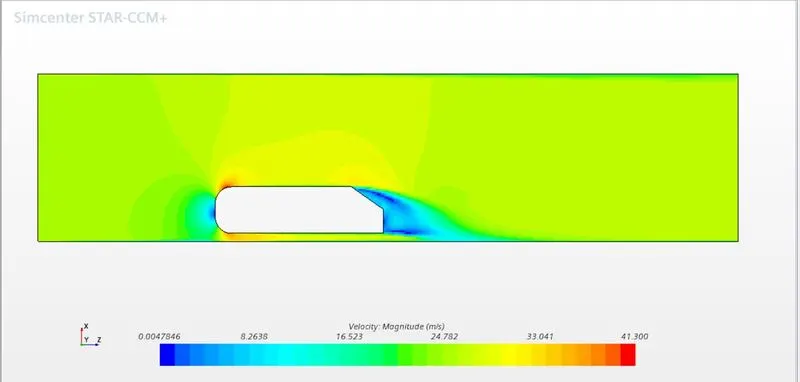
Velocity Contour:
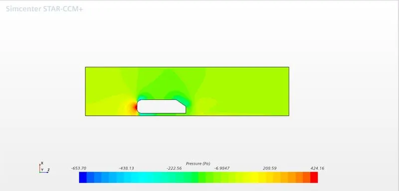
Pressure contour:
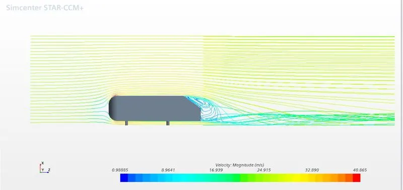
velocity streamlines:
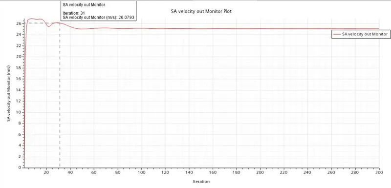
velocity at outlet:
velocity profile at different distances from start:
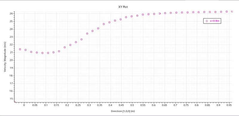
Velocity at x=0.8 m
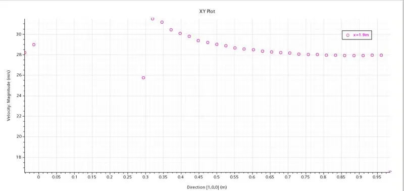
Velocity at x=1.9 m
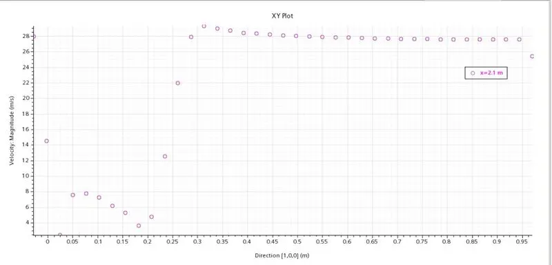
Velocity at x=2.1 m
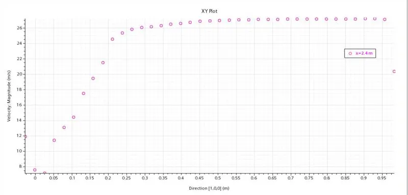
velocity at x=2.4 m
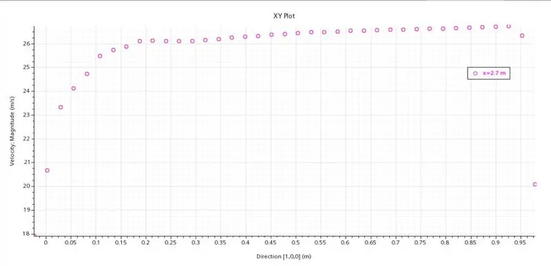
Velocity at x=2.7 m
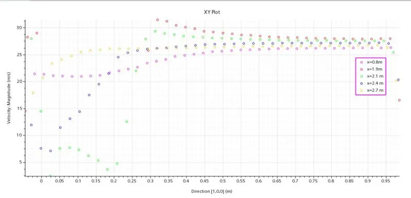
Velocity at all line probes:
Drag and lift values:
drag coeff value:

Lift coeff value:

Results for velocity line probe for both 25 deg and 35 deg:
link for .csv file:
https://drive.google.com/drive/folders/1DisE6ZlIMYwCRJkJzV739tcrft1sP6vr?usp=sharing
Comparision of velocity profile by plot:
If we look at the above plots for slant height 25 and 35 there is a considerable similarities in the velocity profile from x=0.3m to x=0.9m which takes in account for the slant region and wake region along y axis.
This give a pretty good image for value ranging in these plots.
Conclusions and inferences:
- The drag and lift coefficient can be more accurate and the drag coefficient can come under 0.4 but that needs more fine mesh and needs different y+ grid dependency test
- The major y+ of 10 was selected but upon finer mesh good results for upto y+ of 50 can be achieved
- The velocity profile formed on the plot seems to be acurate and shows the behaviour of fluid along y axis.
- The streamlines in the wake region shows negative pressure regions which comprises of turbulence regions and flow separation so the velocity profile at wake regions shows abrupt changes.
- The model k-epsilon was chosen as it resolves good for ahmed body for both the slant angles and gave good results
- The k-omega model can give good results but since the y+ is not so low below 5 so the k-omega is not so needed.
- But for drag coeff on a car we should prefer k-omega sst since its not susceptible to high free stream velocities and gives good results and its pretty stable under grid dependancy test.
- In this case k-epsilon realizable was chosen to reduce computational time and power.
sim files:
https://drive.google.com/file/d/1wr4ZlbPzYPp5reFTjpWHAEkMO7BIwJ4N/view?usp=sharing
https://drive.google.com/file/d/1a7ir0bwws7uvwRld633luQDnzkhuuNBO/view?usp=sharing