Week 8 - BlockMesh Drill down challenge
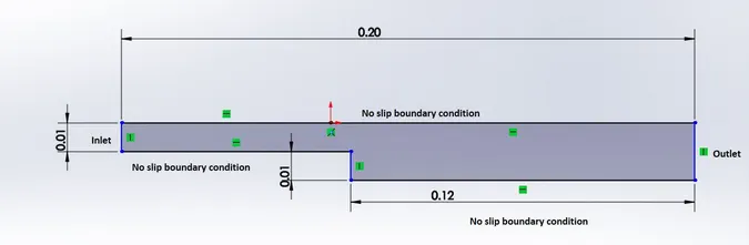
Aim : In this project we analyse the velocity profile of the geometry which have the following figure using Blockmesh in OpenFoam.
Mesh specification
- Number of cells along the x direction (longer dimension) = 200
- Number of cells along the y direction = 10
- Use a graded mesh. Grading factor near all walls should be 0.2
figure:
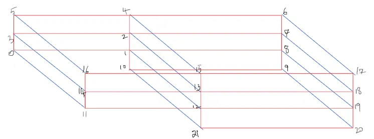
Description: The vertices are descibed in x,y,z axes and and labelled from 0 to 21 axes which sums up to 22 axes. By breaking down the structure into back and front sections.
The mesh is generated using Blockmesh after defining the vertices of the geometry.
Mesh grading factor of 0.2,0.5,0.8 is applied to see the changes in velocity magnitude contour.
The solver used for is icoFoam solver.
paraFoam is used for visuaizing and post processing the results
Boundary condition:
inlet velocity is 0.01m/s
outlet pressure is atmospheric to zero
kinematic viscosity of water is taken i.e 0.00000178m^2/s
BlockMeshDict Structure:
/*--------------------------------*- C++ -*----------------------------------*\
  =========                 |
  \\      /  F ield         | OpenFOAM: The Open Source CFD Toolbox
   \\    /   O peration     | Website:  https://openfoam.org
    \\  /    A nd           | Version:  8
     \\/     M anipulation  |
\*---------------------------------------------------------------------------*/
FoamFile
{
    version     2.0;
    format      ascii;
    class       dictionary;
    object      blockMeshDict;
}
// * * * * * * * * * * * * * * * * * * * * * * * * * * * * * * * * * * * * * //

// Note: this file is a Copy of $FOAM_TUTORIALS/resources/blockMesh/pitzDaily

convertToMeters 1;

vertices
(
    (0 0 0)//0
    (0.08 0 0)//1
    (0.08 0.01 0)//2
    (0 0.01 0)//3
    (0.08 0.02 0)//4
    (0 0.02 0)//5
    (0.20 0.02 0)//6
    (0.20 0.01 0)//7
    (0.20 0 0)//8
    (0.20 -0.01 0)//9
    (0.08 -0.01 0)//10

    (0 0 0.001)//11
    (0.08 0 0.001)//12
    (0.08 0.01 0.001)//13
    (0 0.01 0.001)//14
    (0.08 0.02 0.001)//15
    (0 0.02 0.001)//16
    (0.20 0.02 0.001)//17
    (0.20 0.01 0.001)//18
    (0.20 0 0.001)//19
    (0.20 -0.01 0.001)//20
    (0.08 -0.01 0.001)//21
);

blocks
(
    hex (0 1 2 3 11 12 13 14)
    (200 10 1)
    simpleGrading (0.2 1.2 1)

    hex (3 2 4 5 14 13 15 16)
    (200 10 1)
    simpleGrading (0.2 0.2 1)

    hex (2 7 6 4 13 18 17 15)
    (200 10 1)
    simpleGrading (1.2 0.2 1)

    hex (1 8 7 2 12 19 18 13)
    (200 10 1)
    simpleGrading (1.2 1.2 1)

    hex (10 9 8 1 21 20 19 12)
    (200 10 1)
    simpleGrading (1.2 1.2 1)
);

edges
(
);

boundary
(
    inlet
    {
        type patch;
        faces
        (
            (0 11 14 3)
            (3 14 16 5)
        );
    }
    outlet
    {
        type patch;
        faces
        (
            (9 8 19 20)
            (8 7 18 19)
            (7 6 17 18)
        );
    }
    upperWallNoSlip
    {
        type wall;
        faces
        (
            (16 15 4 5)
            (15 17 6 4)

        );
    }
    lowerWallNoSlip
    {
        type wall;
        faces
        (
            (0 1 12 11)
            (10 21 12 1)
            (10 9 20 21)
        );
    }
    frontAndBack
    {
        type empty;
        faces
        (
            (0 3 2 1)
            (3 5 4 2)
            (2 4 6 7)
            (1 2 7 8)
            (10 1 8 9)
            (11 12 13 14)
            (14 13 15 16)
            (13 18 17 15)
            (12 19 18 13)
            (21 20 19 12)
        );
    }
);

mergePatchPairs
(
);

// ************************************************************************* //
Pressure(p) Boundary conditions text file:
/*--------------------------------*- C++ -*----------------------------------*\
  =========                 |
  \\      /  F ield         | OpenFOAM: The Open Source CFD Toolbox
   \\    /   O peration     | Website:  https://openfoam.org
    \\  /    A nd           | Version:  8
     \\/     M anipulation  |
\*---------------------------------------------------------------------------*/
FoamFile
{
    version     2.0;
    format      ascii;
    class       volScalarField;
    object      p;
}
// * * * * * * * * * * * * * * * * * * * * * * * * * * * * * * * * * * * * * //

dimensions      [0 2 -2 0 0 0 0];

internalField   uniform 0;

boundaryField
{
    inlet
    {
        type            zeroGradient;
    }

    outlet
    {
        type            fixedValue;
        value           uniform 0;
    }

    frontAndBack
    {
        type            empty;
    }

    upperWallNoSlip
    {
        type            zeroGradient;
    }

    lowerWallNoSlip
    {
        type            zeroGradient;
    }
}

// ************************************************************************* //
Velocit(U) boundary condition text file:
/*--------------------------------*- C++ -*----------------------------------*\
  =========                 |
  \\      /  F ield         | OpenFOAM: The Open Source CFD Toolbox
   \\    /   O peration     | Website:  https://openfoam.org
    \\  /    A nd           | Version:  8
     \\/     M anipulation  |
\*---------------------------------------------------------------------------*/
FoamFile
{
    version     2.0;
    format      ascii;
    class       volVectorField;
    object      U;
}
// * * * * * * * * * * * * * * * * * * * * * * * * * * * * * * * * * * * * * //

dimensions      [0 1 -1 0 0 0 0];

internalField   uniform (0 0 0);

boundaryField
{
    inlet
    {
        type            fixedValue;
        value           uniform (0.01 0 0);
    }

    outlet
    {
        type            zeroGradient;
    }

    upperWallNoSlip
    {
        type            noSlip;
    }

    lowerWallNoSlip
    {
        type            noSlip;
    }

    frontAndBack
    {
        type            empty;
    }
}

// ************************************************************************* //
Transport properties text file:
/*--------------------------------*- C++ -*----------------------------------*\
  =========                 |
  \\      /  F ield         | OpenFOAM: The Open Source CFD Toolbox
   \\    /   O peration     | Website:  https://openfoam.org
    \\  /    A nd           | Version:  8
     \\/     M anipulation  |
\*---------------------------------------------------------------------------*/
FoamFile
{
    version     2.0;
    format      ascii;
    class       dictionary;
    location    "constant";
    object      transportProperties;
}
// * * * * * * * * * * * * * * * * * * * * * * * * * * * * * * * * * * * * * //

nu              [0 2 -1 0 0 0 0] 0.000001;


// ************************************************************************* //
here in the above transport proiperties nu kinematic viscosity is 1e-6 or 0.00000178 m^2/s is taken
control Dict text file:
/*--------------------------------*- C++ -*----------------------------------*\
  =========                 |
  \\      /  F ield         | OpenFOAM: The Open Source CFD Toolbox
   \\    /   O peration     | Website:  https://openfoam.org
    \\  /    A nd           | Version:  8
     \\/     M anipulation  |
\*---------------------------------------------------------------------------*/
FoamFile
{
    version     2.0;
    format      ascii;
    class       dictionary;
    location    "system";
    object      controlDict;
}
// * * * * * * * * * * * * * * * * * * * * * * * * * * * * * * * * * * * * * //

application     icoFoam;

startFrom       startTime;

startTime       0;

stopAt          endTime;

endTime         5;

deltaT          0.005;

writeControl    timeStep;

writeInterval   10;

purgeWrite      1;

writeFormat     ascii;

writePrecision  6;

writeCompression off;

timeFormat      general;

timePrecision   6;

runTimeModifiable true;


// ************************************************************************* //
fvSchemes text file:
/*--------------------------------*- C++ -*----------------------------------*\
  =========                 |
  \\      /  F ield         | OpenFOAM: The Open Source CFD Toolbox
   \\    /   O peration     | Website:  https://openfoam.org
    \\  /    A nd           | Version:  8
     \\/     M anipulation  |
\*---------------------------------------------------------------------------*/
FoamFile
{
    version     2.0;
    format      ascii;
    class       dictionary;
    location    "system";
    object      fvSchemes;
}
// * * * * * * * * * * * * * * * * * * * * * * * * * * * * * * * * * * * * * //

ddtSchemes
{
    default         Euler;
}

gradSchemes
{
    default         Gauss linear;
    grad(p)         Gauss linear;
}

divSchemes
{
    default         none;
    div(phi,U)      Gauss linear;
}

laplacianSchemes
{
    default         Gauss linear orthogonal;
}

interpolationSchemes
{
    default         linear;
}

snGradSchemes
{
    default         orthogonal;
}


// ************************************************************************* //
fvSolution text file:
/*--------------------------------*- C++ -*----------------------------------*\
  =========                 |
  \\      /  F ield         | OpenFOAM: The Open Source CFD Toolbox
   \\    /   O peration     | Website:  https://openfoam.org
    \\  /    A nd           | Version:  8
     \\/     M anipulation  |
\*---------------------------------------------------------------------------*/
FoamFile
{
    version     2.0;
    format      ascii;
    class       dictionary;
    location    "system";
    object      fvSolution;
}
// * * * * * * * * * * * * * * * * * * * * * * * * * * * * * * * * * * * * * //

solvers
{
    p
    {
        solver          PCG;
        preconditioner  DIC;
        tolerance       1e-06;
        relTol          0.05;
    }

    pFinal
    {
        $p;
        relTol          0;
    }

    U
    {
        solver          smoothSolver;
        smoother        symGaussSeidel;
        tolerance       1e-05;
        relTol          0;
    }
}

PISO
{
    nCorrectors     2;
    nNonOrthogonalCorrectors 0;
    pRefCell        0;
    pRefValue       0;
}


// ************************************************************************* //
For grading factor remaing code remains the same except for the
grading factor for 0.2:
blocks
(
    hex (0 1 2 3 11 12 13 14)
    (200 10 1)
    simpleGrading (0.2 1.2 1)

    hex (3 2 4 5 14 13 15 16)
    (200 10 1)
    simpleGrading (0.2 0.2 1)

    hex (2 7 6 4 13 18 17 15)
    (200 10 1)
    simpleGrading (1.2 0.2 1)

    hex (1 8 7 2 12 19 18 13)
    (200 10 1)
    simpleGrading (1.2 1.2 1)

    hex (10 9 8 1 21 20 19 12)
    (200 10 1)
    simpleGrading (1.2 1.2 1)
);
grading factor for 0.5:
blocks
(
    hex (0 1 2 3 11 12 13 14)
    (200 10 1)
    simpleGrading (0.5 1.5 1)

    hex (3 2 4 5 14 13 15 16)
    (200 10 1)
    simpleGrading (0.5 0.5 1)

    hex (2 7 6 4 13 18 17 15)
    (200 10 1)
    simpleGrading (1.5 0.5 1)

    hex (1 8 7 2 12 19 18 13)
    (200 10 1)
    simpleGrading (1.5 1.5 1)

    hex (10 9 8 1 21 20 19 12)
    (200 10 1)
    simpleGrading (1.5 1.5 1)
);
grading factor for 0.8:
blocks
(
    hex (0 1 2 3 11 12 13 14)
    (200 10 1)
    simpleGrading (0.8 1.8 1)

    hex (3 2 4 5 14 13 15 16)
    (200 10 1)
    simpleGrading (0.8 0.8 1)

    hex (2 7 6 4 13 18 17 15)
    (200 10 1)
    simpleGrading (1.8 0.8 1)

    hex (1 8 7 2 12 19 18 13)
    (200 10 1)
    simpleGrading (1.8 1.8 1)

    hex (10 9 8 1 21 20 19 12)
    (200 10 1)
    simpleGrading (1.8 1.8 1)
);
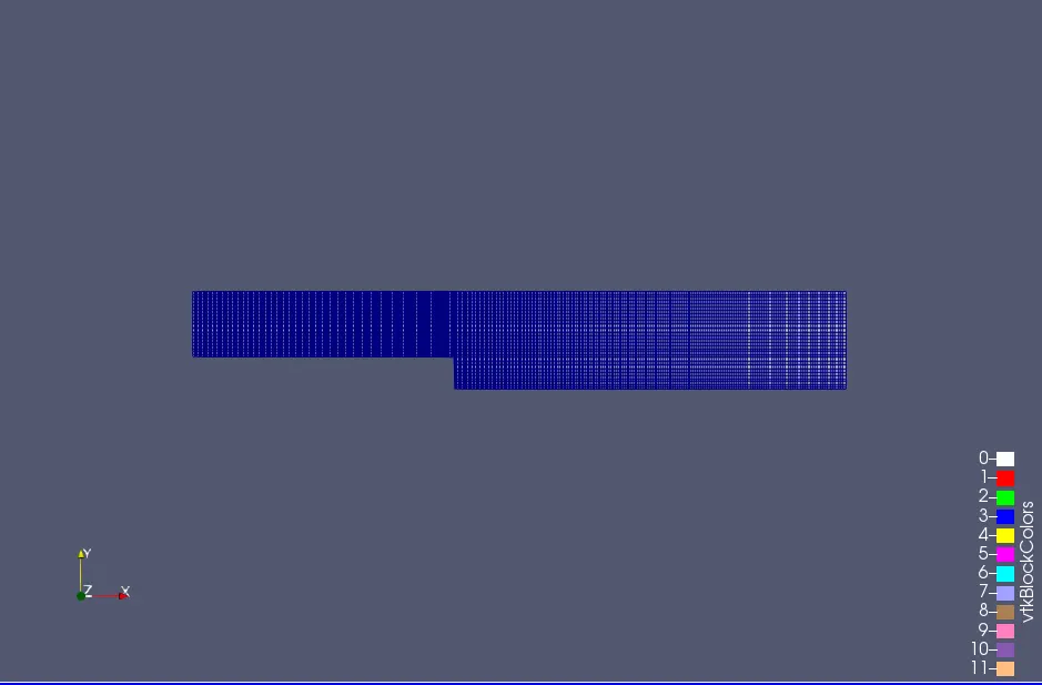
The mesh is generated for 0.2,0.5,0.8:
Grading factor= size of last cell/size of first cell
grading factor 0.2 grading factor 0.5
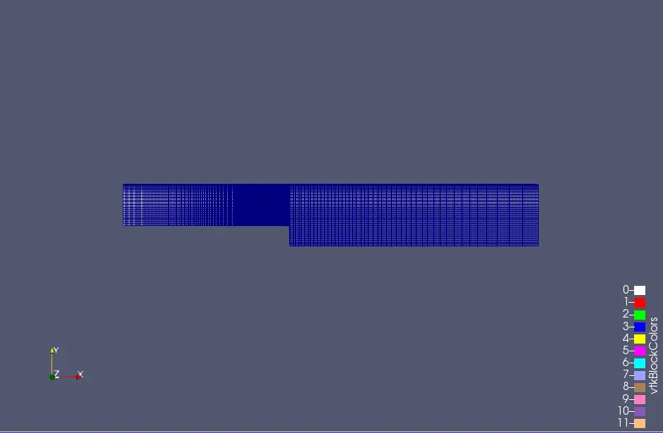
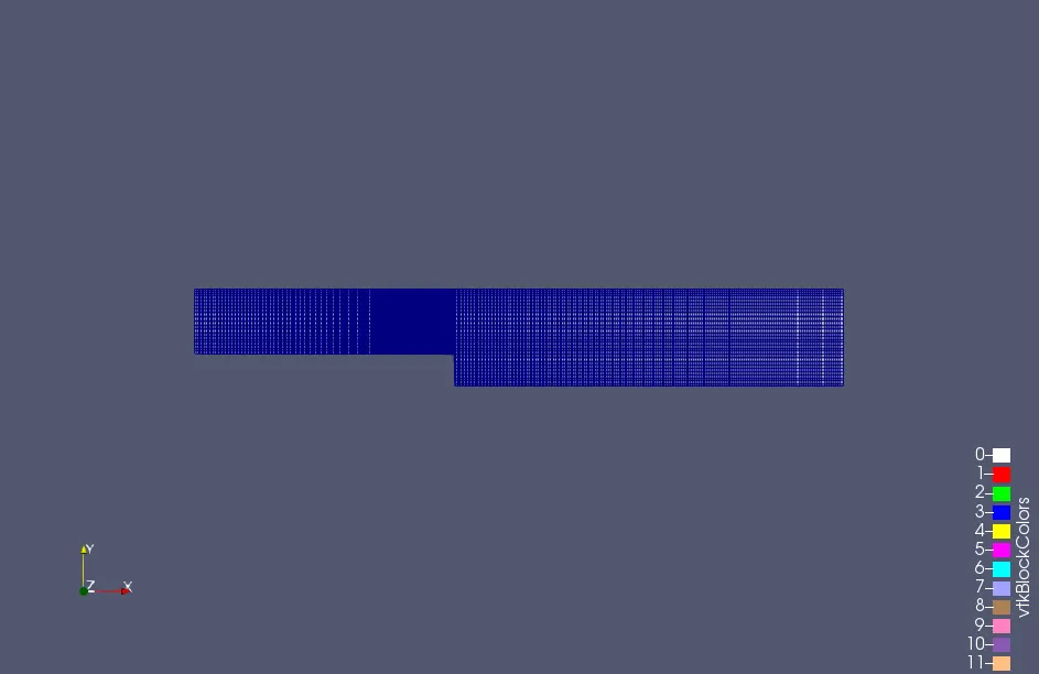
grading factor 0.8
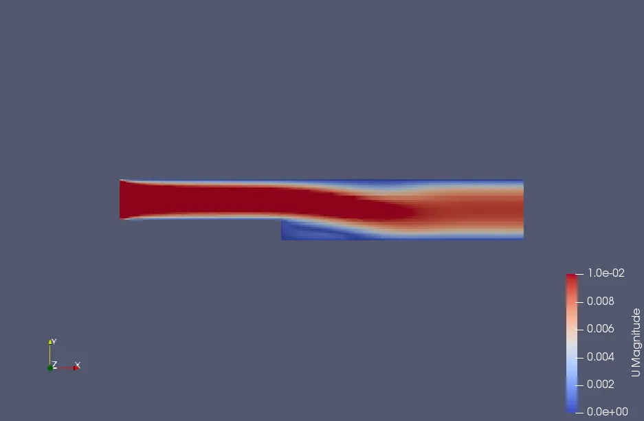
velocity contour:
for mesh grading 0.2 for mesh grading 0.5
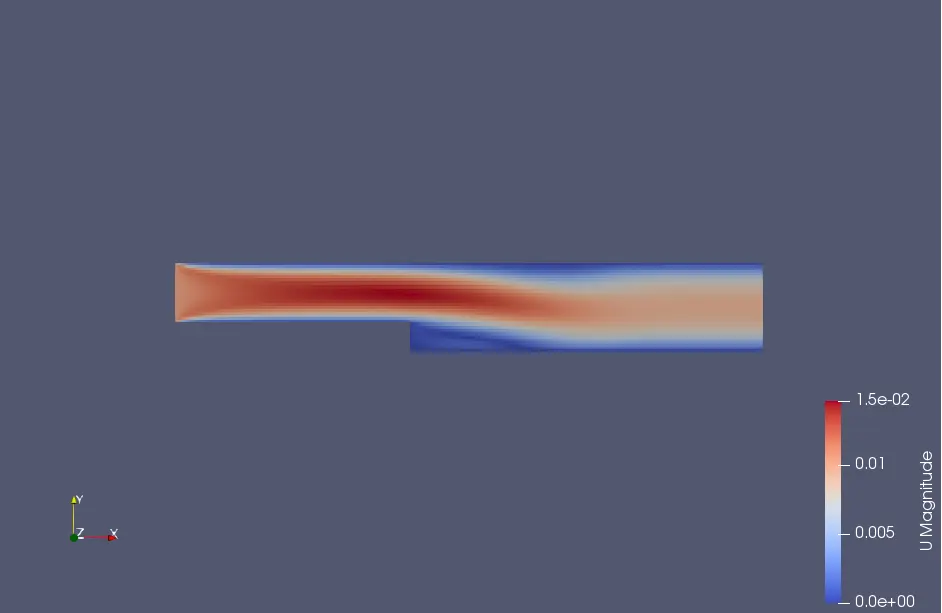
for mesh grading 0.8
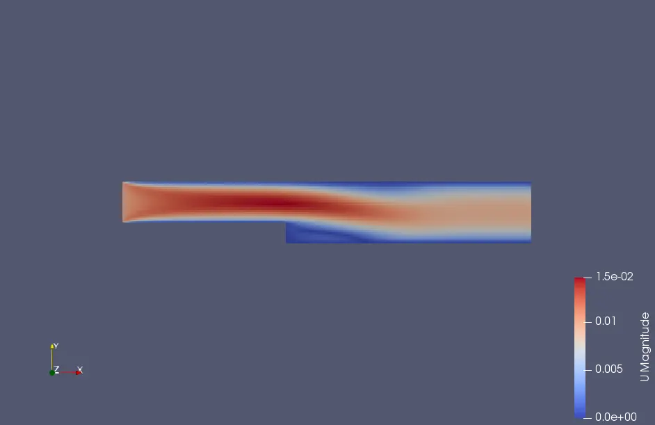
Expanation for velocity contours:
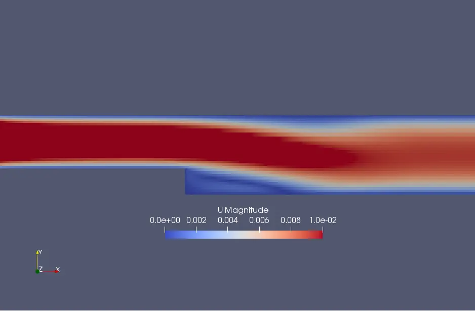
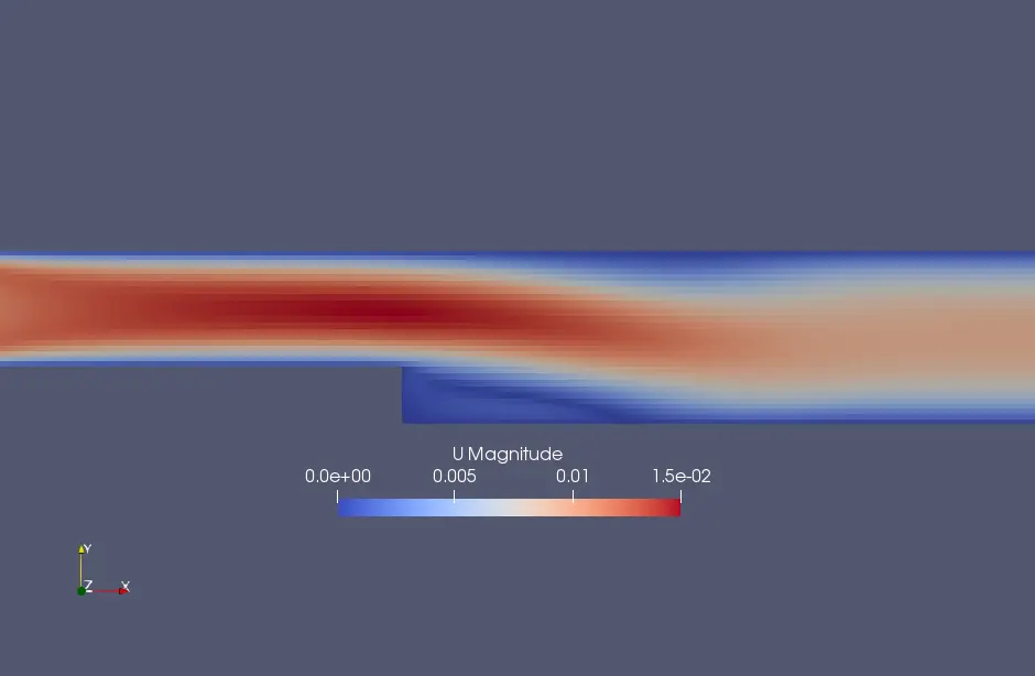
We can observe that there is minimum difference between the mesh grading factor 0.5 and 0.8. But the red region near the inlet face till the length 0.08m ;red region thickness is decreasing
as mesh grading factor increases. The reason should be the fact that the walls are finely meshed than that of interiors due to grading factor and the smooth transition can be seen for different
grading factors.
Velocity magnitude plot:
for grading factor 0.2 for grading factor 0.5 for grading factor 0.8
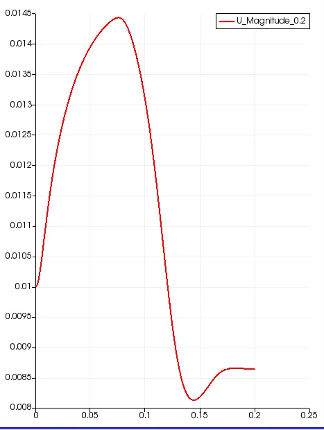
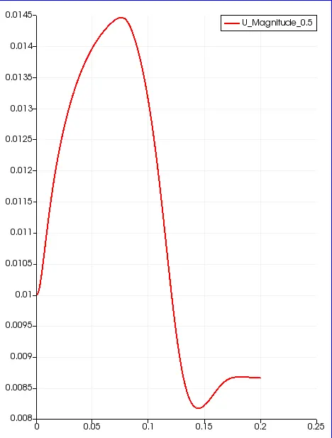
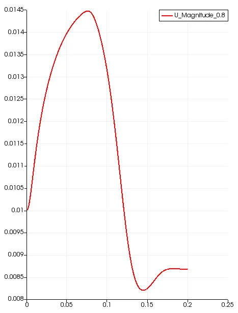
Explanation for velocity magnitude plot: length vs velocity
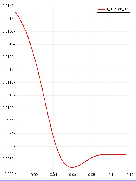
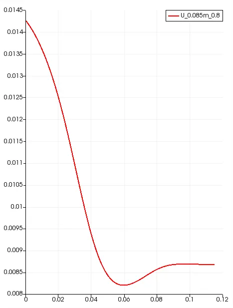
The plots are very much descriptive and there is very less difference in the peak velocity for three plots. according to my understanding it fairly makes any difference in
considering the grading factor ; to be more precise the difference is in 0.01 absolute value of velocity
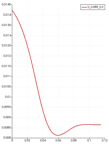
velocity profile at 0.085m from inlet:
grading factor 0.2 grading factor 0.5 grading factor 0.8
velocity contour at the step region:
for grading factor 0.2
for garding factor 0.5
for grading factor 0.8
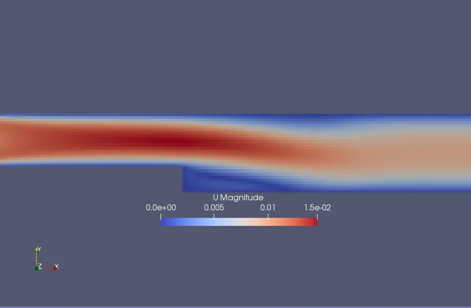
Explanation at the step part of the block:
There are small turbulence or flow reversel or edddies which can be seen if kinematic viscosity is increased a bit more to 1e-5. the present case have the nu value as 0.00000178 m^2/s.
this small eddies can be avoided by smoothning the inner surface for better streamlining the block.
Courant number comparison with different grading factors:
| Mesh grading factor | 0.8 | 0.5 | 0.2 |
| Courant number mean | 0.0788495 | 0.0788127 | 0.0787425 |
| Courant number maximum | 0.205723 | 0.264225 | 0.45288 |
| Execution time | 113.7s | 112.3s | 118.6s |
| Number of iterations | 82 | 83 | 83 |
Explantion for courant number table:
As we can see that as mesh grading factor increases the courant number maximum decreases ,this is due to the fact that courant number is inversely proportional to `Deltax`
since `C=(Deltat)/(Deltax)(a+V)` . But alone `Deltax`is not responsiible but the time steps `Deltat` plays a major role , as we alter the values of `Deltat`there will be a direct impact
on courant number as they are directly proportional . so as `Deltax` is increased `Deltat` shoud be decresed so as to compensate and to make the solution stable or the solver will
automatically stop to execute.
In conclusion optimal grading factor and time steps should be chosen to avoid closer of solver and to reduce the execution time.