Project 1 _Creating an Architectural plan for the provided plot size and develop relevant basic structural drawings
*AVERY DIMENSION GIVEN IN THE DRAWING
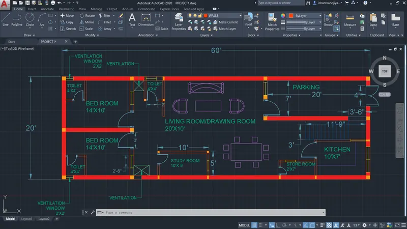
AIM: Design and Draft a layout of a residential building with the Plot Size: 60’x20’(18.3m x6m) Facing East.
Introduction: In this challenge, I have drafted the above-mentioned drawing i.e, Design and Draft a layout of a residential building with the Plot Size: 60’x20’(18.3m x6m) Facing East, using AutoCad. here in this challenge, I have attached all the drawings in an image format and with the proper procedure as possible.
PROCEDURE:
1. ARCHITECTURAL DRAWING
A. FLOOR PLAN
- SELECT UN > SELECT ENGINEERING > SELECT PRECISION 0'0">SELECT SACLE INCHES > PRESS OK
- SET LIMITS > SELECT LIMITS COMMAND > GIVE FIRST COORDINATES LEFT BOTTOM CORNER 0'0" > GIVE SECOND COORDINATES RIGHT TOP CORNER 100'0" > PRESS ENTER
- SELECT XLINE COMMAND > SELECT VERTICAL LINE > SPECIFY POINT PRESS ENTER
- SELECT XLINE COMMAND > SELECT HORIZONTAL LINE > SPECIFY POINT > PRESS ENTER
- SELECT OFFSET COMMAND > GIVE DISTANCE 60' > SELECT VERTICAL LINE AS OBJECT > SPECIFY SIDE PRESS ENTER
- AGAIN SELECT OFFSET COMMAND > GIVE DISTANCE 20' > SELECT HORIZONTAL LINE AS OBJECT > SPECIFY SIDE PRESS ENTER
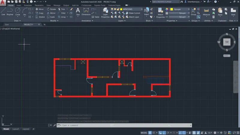
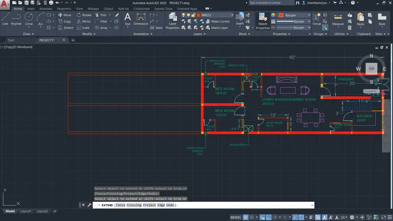
- SKETCH THE DRAWING USING OFFSET COMMAND, TRIM COMMAND, EXTEND COMMAND,
- USING HATCHING TOOL FOR HATCHING THE WALLS
- EXTERNAL WALL 9" AND INTERNAL WALL 4.5"
- USING LAYERS FOR VARIOUS SECTIONS (WALLS, DOORS, WINDOWS, FURNITURE, TEXT, DIMENSION, AND OTHERS)
- LEADER SIZE 3' WIDTH , 9" RISER, 9"TRADE ,3' LANDER
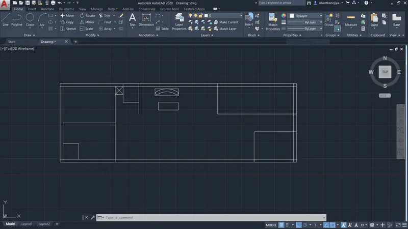
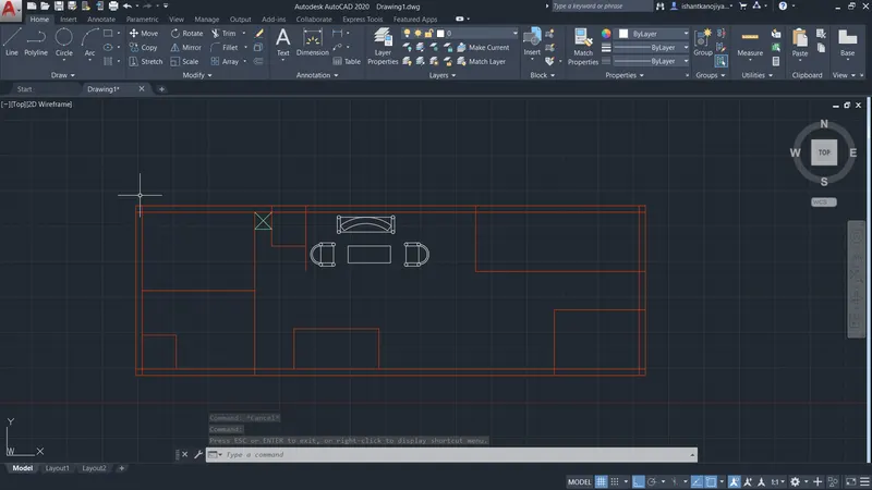
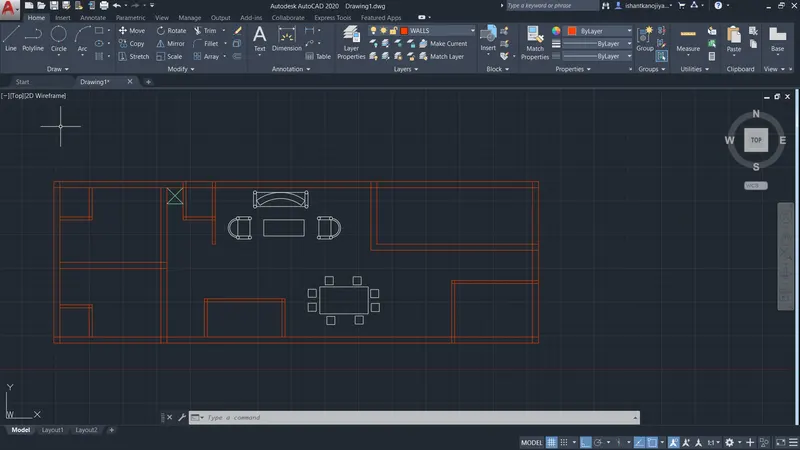
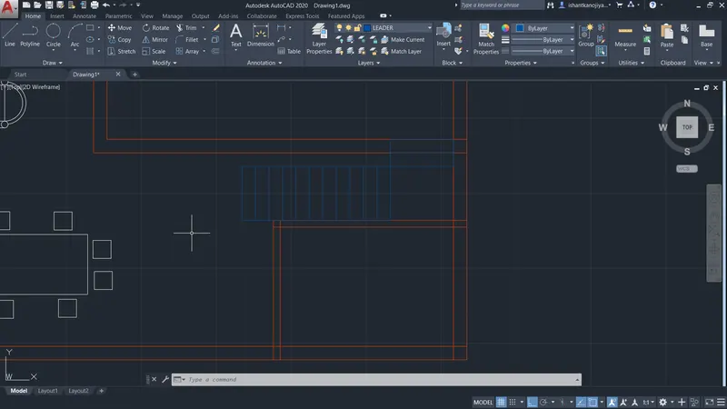
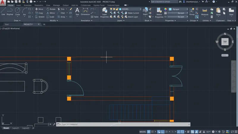
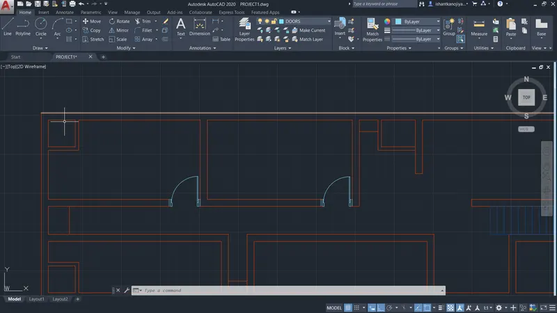
- SKETCHING DOORS AND WINDOWS USING DIFFERENT DIFFERENT LAYERS
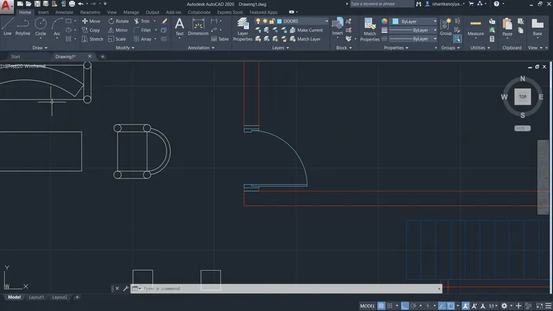
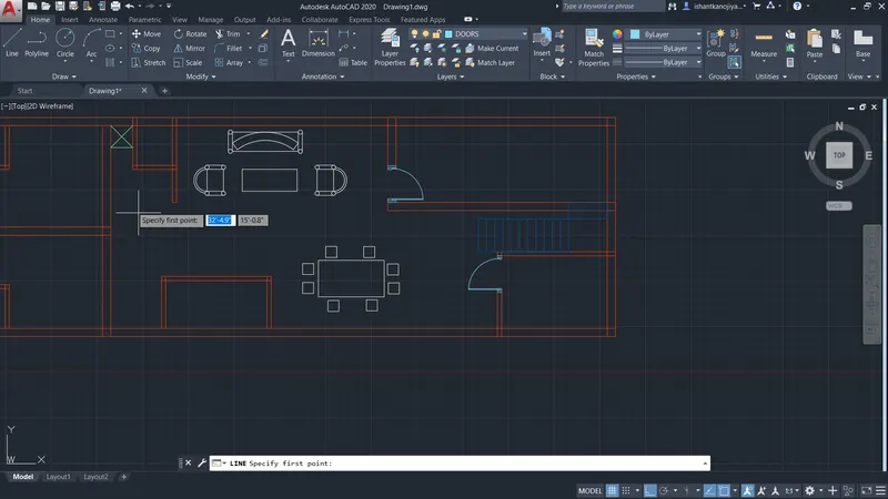
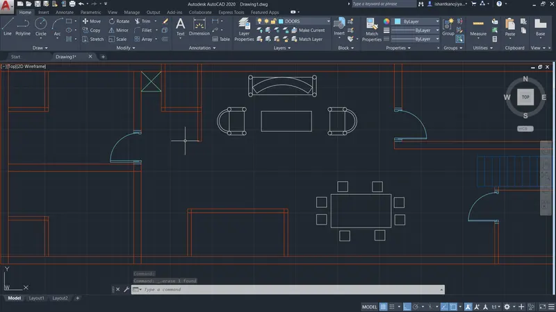
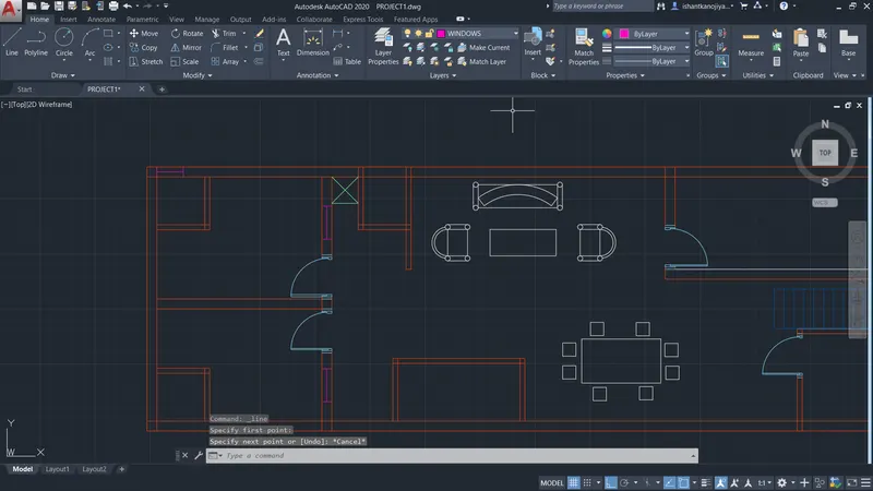
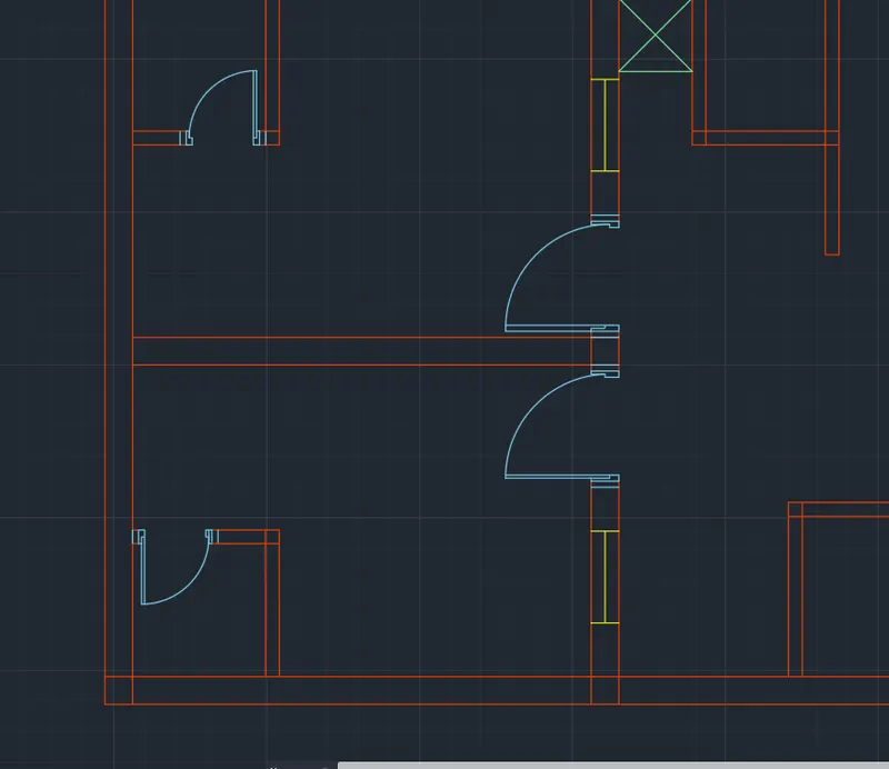
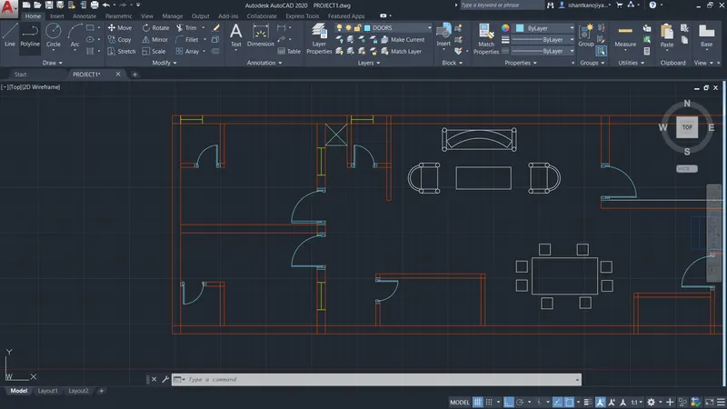
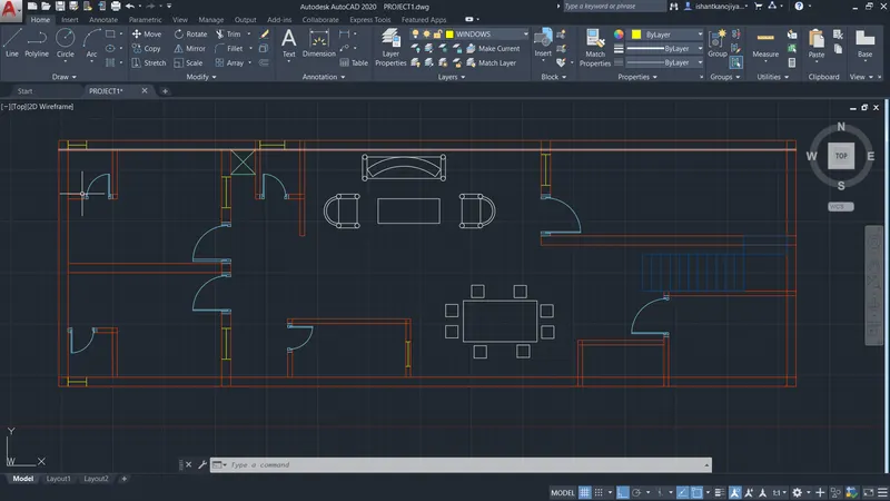
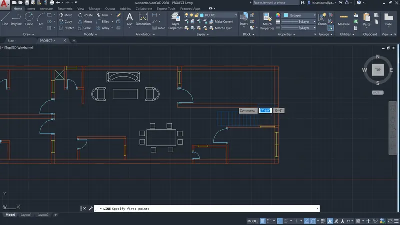
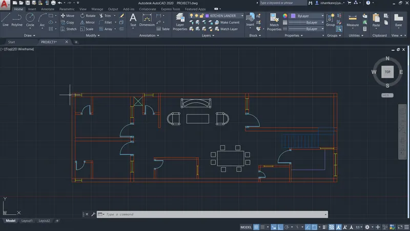
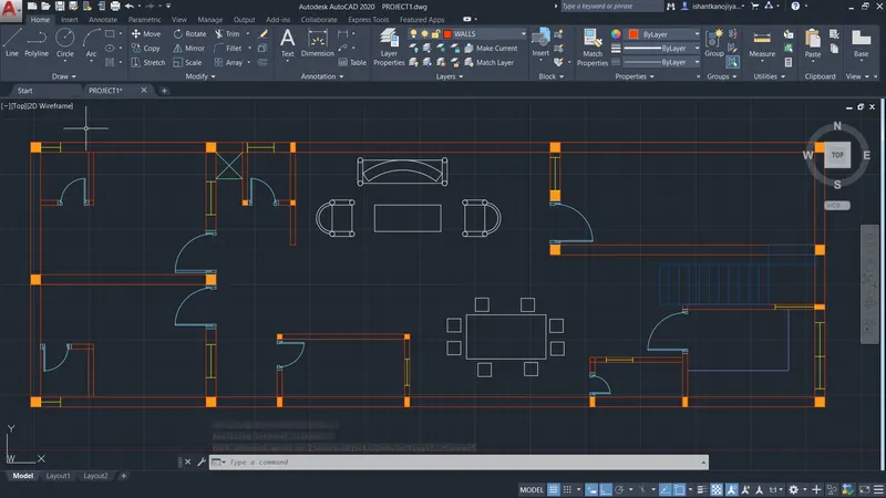
- MAIN DOOR
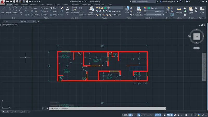
- MULTITEXT COMMAND FOR TEXTING
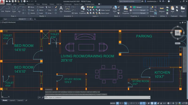
- USING LEADER COMMAND FOR GIVING THE INFORMATION
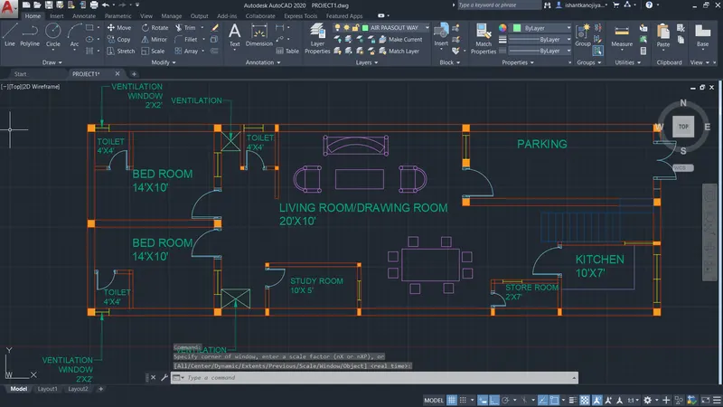
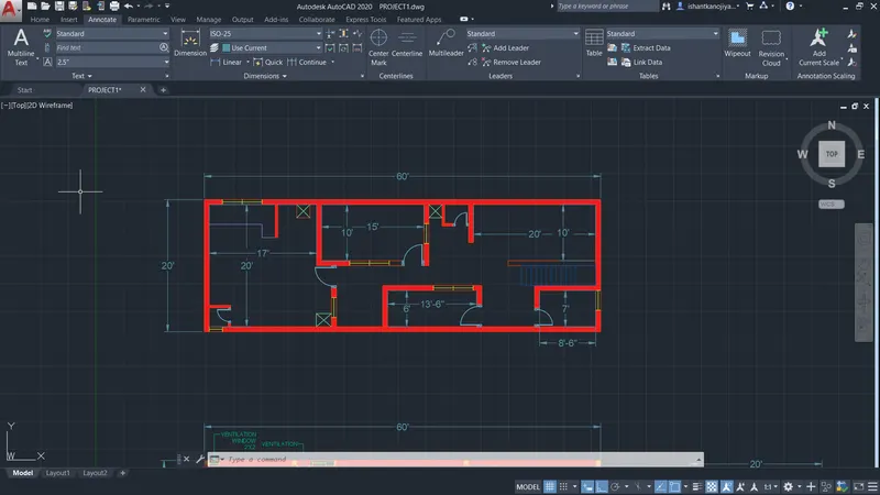
- DIMENSION COMMAND FOR DIMENSIONING
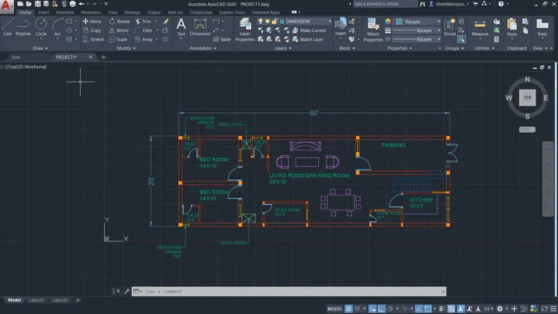
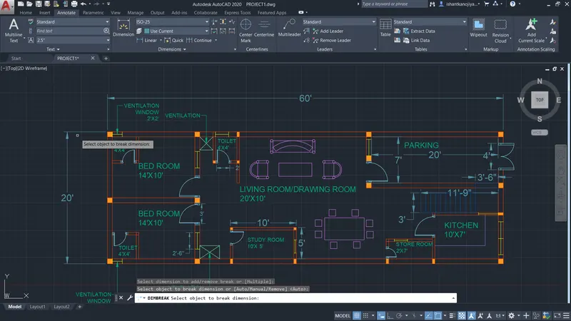
- USING HATCHING TOOL FOR HATCHING
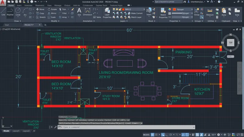
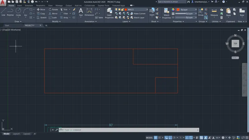
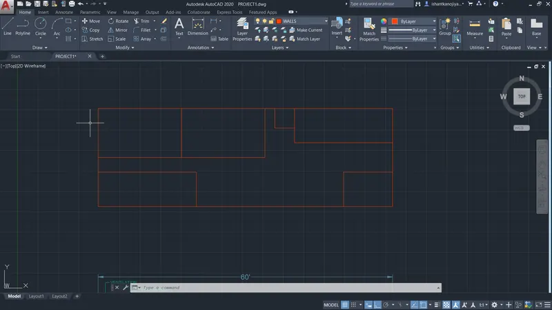
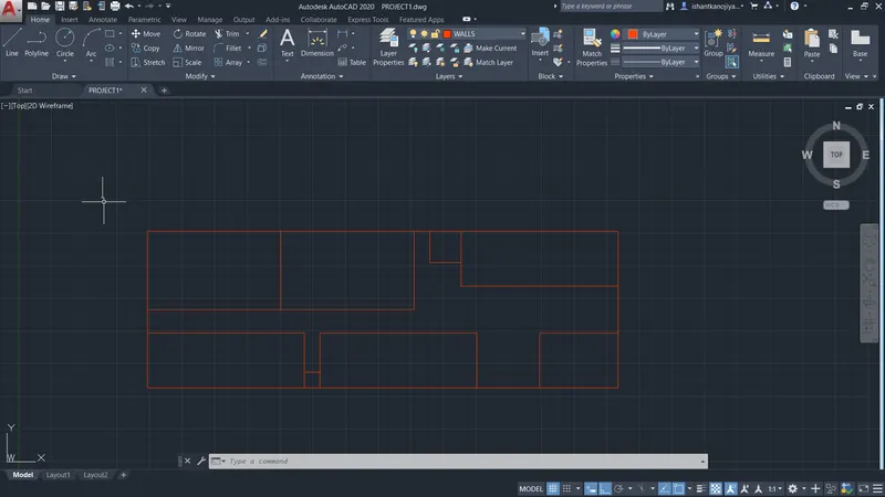
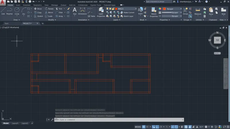
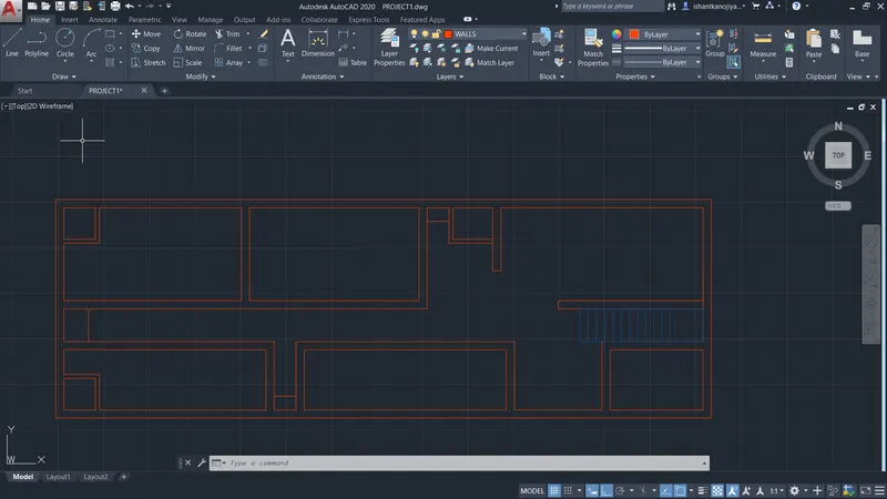
- SOME CHANGES IN ROOMS
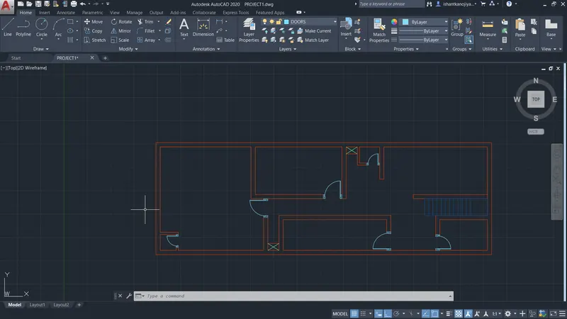
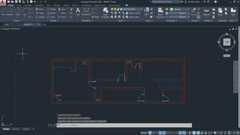
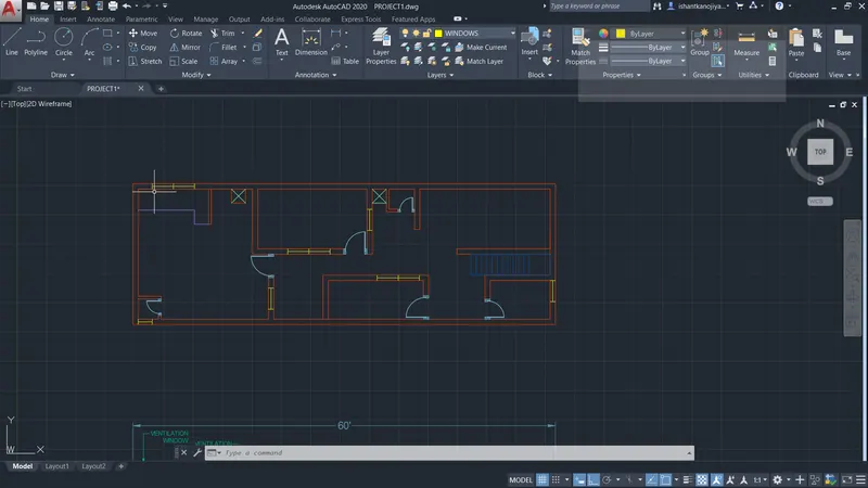
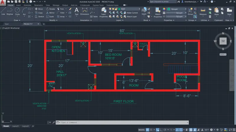
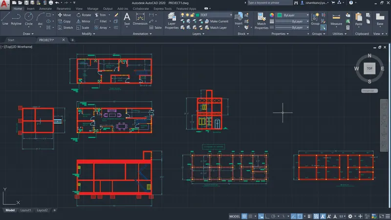
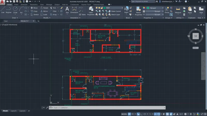
RESULT
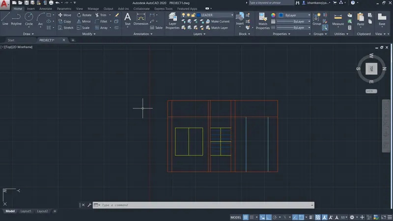
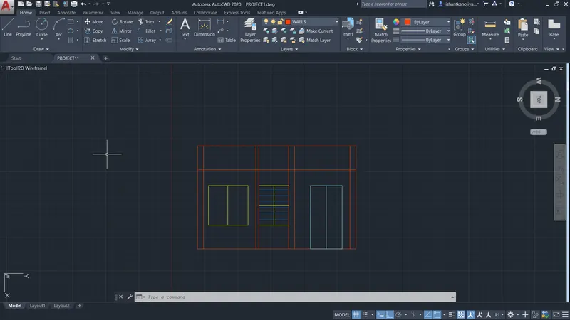
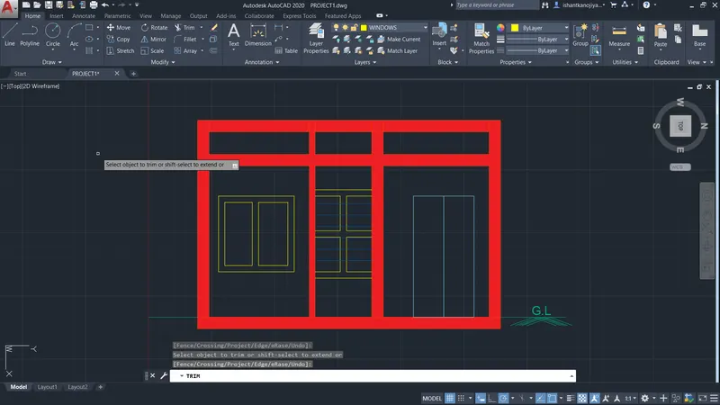
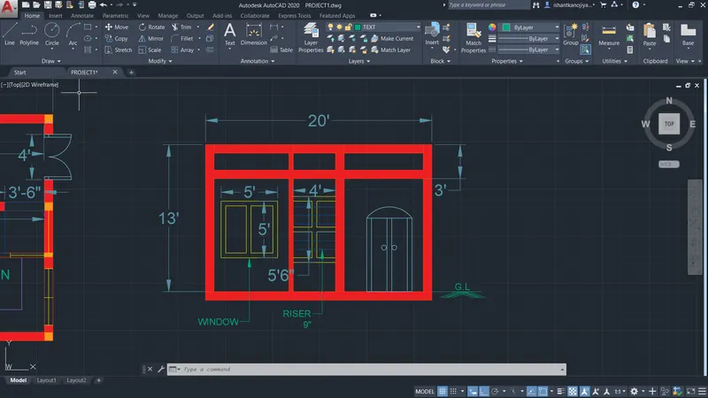
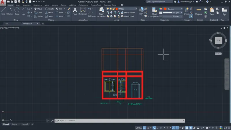
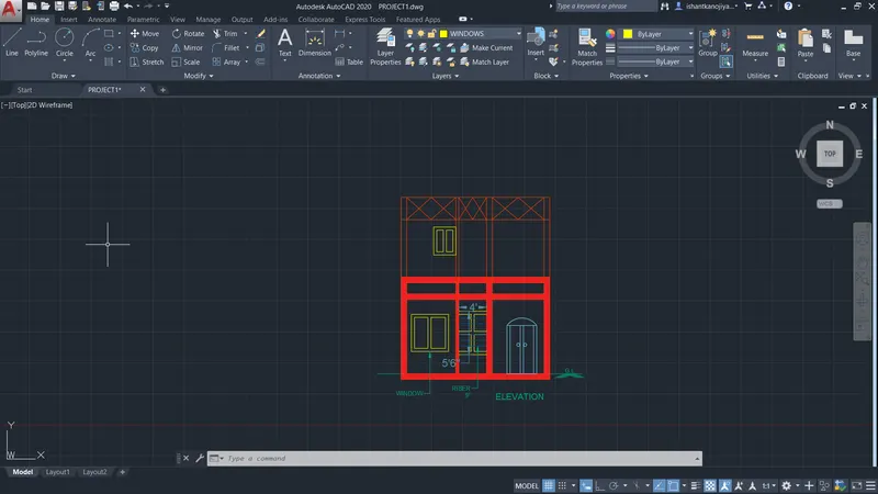
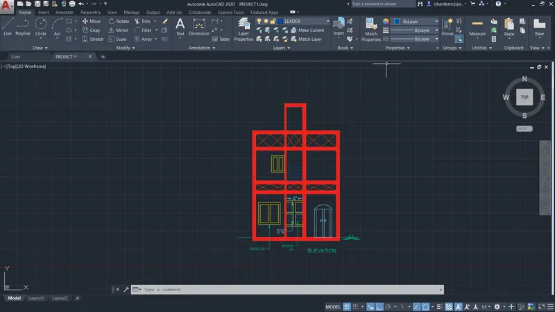
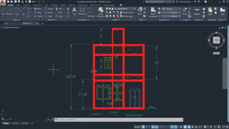
B.ELEVATION
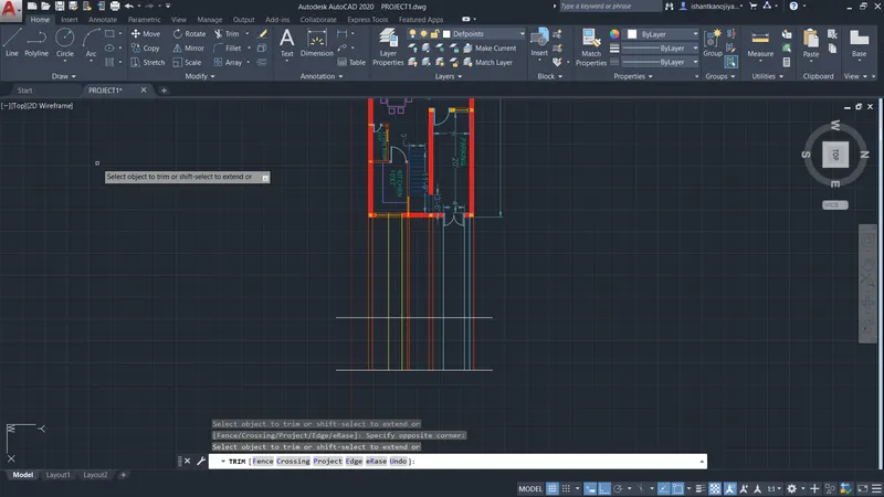
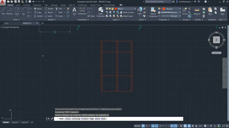
- EXTEND THE LINE USING EXTENSION COMMAND
- WINDOW 5'X5'
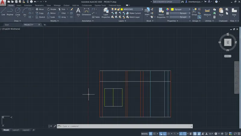

RESULT
C. SECTION-AA
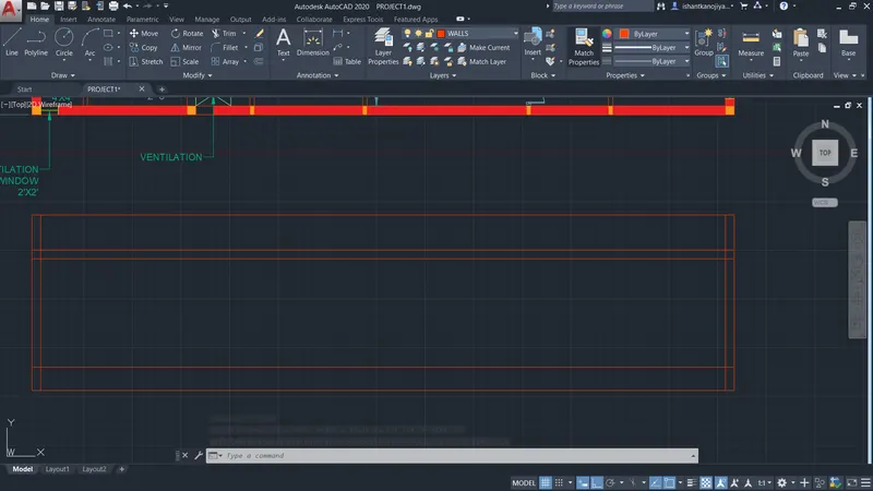
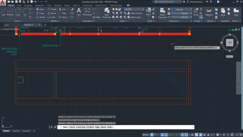
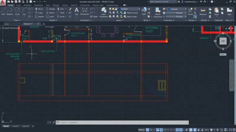
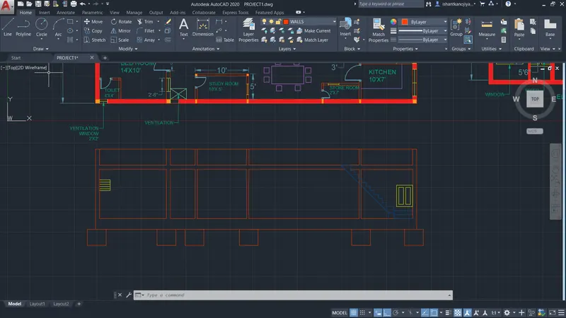
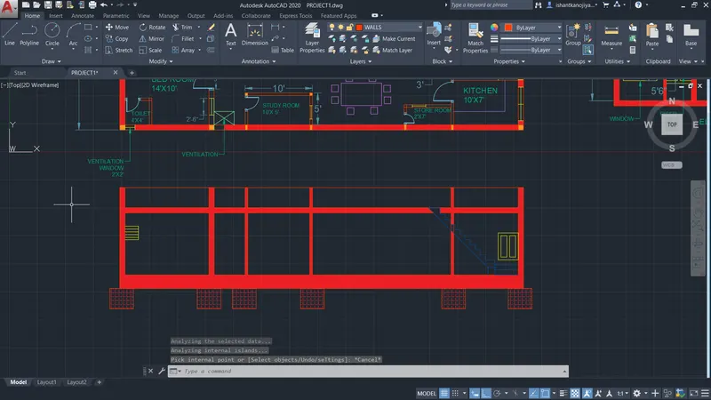
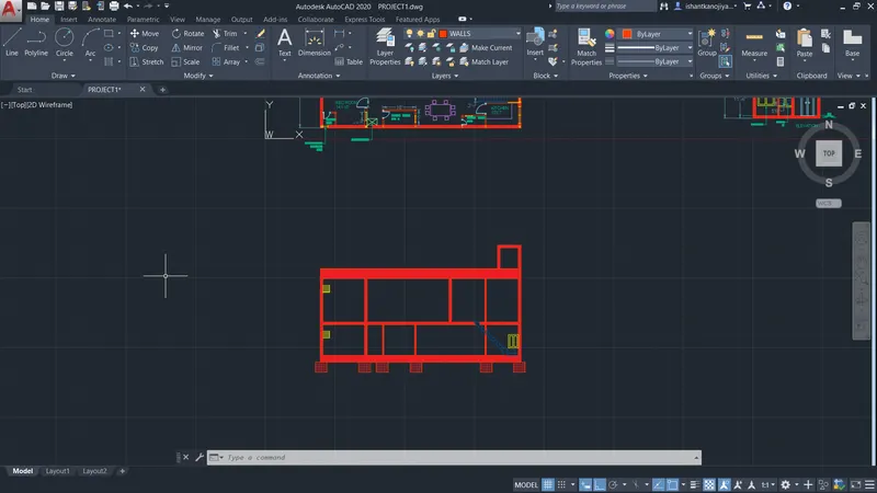
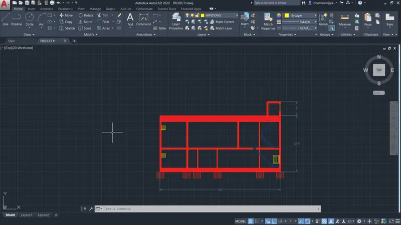
RESULT
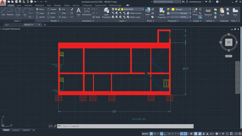
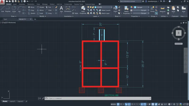
D. SECTION:-BB
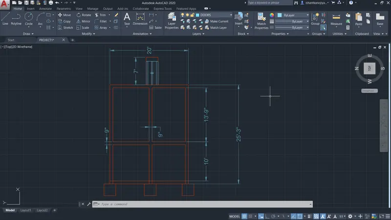
RESULT
2. STRUCTURAL DRAWING
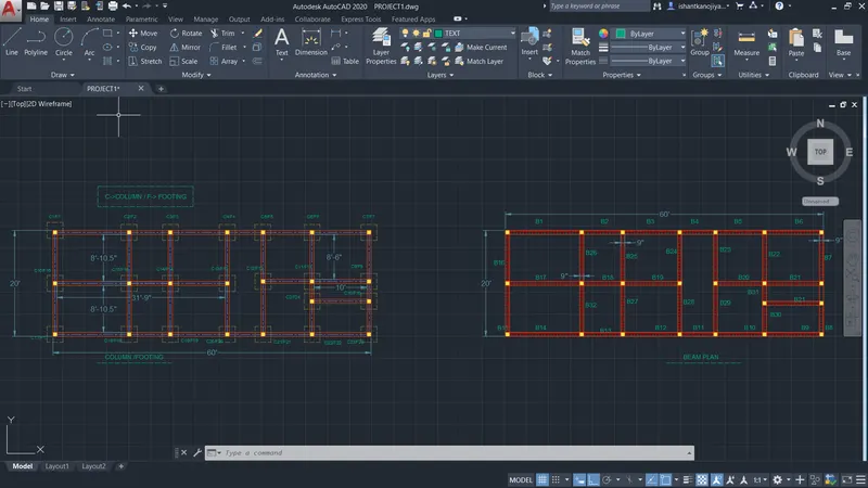
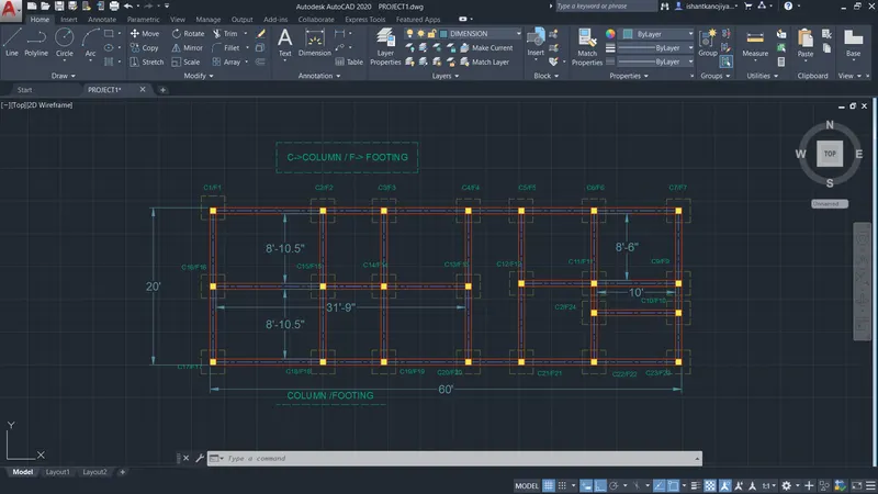
A. COLUMN AND FOOTING DRAWING
- To create a new drawing sheet .
- Type ,,UN’ to set the units of current format of measure.( FEET and INCHES)
- Type ,,LIMITS’ to set the maximum dimension limits on the particular page.
- To take the Column place from the reference of Floor plan.
- Then, to analyze the loading calculation of the entire building for provide the footing designs.
- The projection line is drawn from floor plan required Size.
- Here , we select the column size is 1’ x 9” and 9” x 9”
- The footing size is 4’ x 4’ and 4’6” x 4’6”.
- The Grid lines is drawn to centroidal axis of the column marking to fix the column .
- To give the name of each and every grid lines for better understading.
- Type ,, Tr’ – Trim command is used to trims off an objects cutting the extra edges on objects.
- Type ,, Text’ to create the text ( SINGLE or MULTI ), select and change the properties of standard size.
- COPY – this commands is used to selected objects from a given square to destination, learning a copy at the originally selected location.
- ROTATE – rotate the objects around a specified point.
- MOVE – moves the objects to the destination place from the source place.
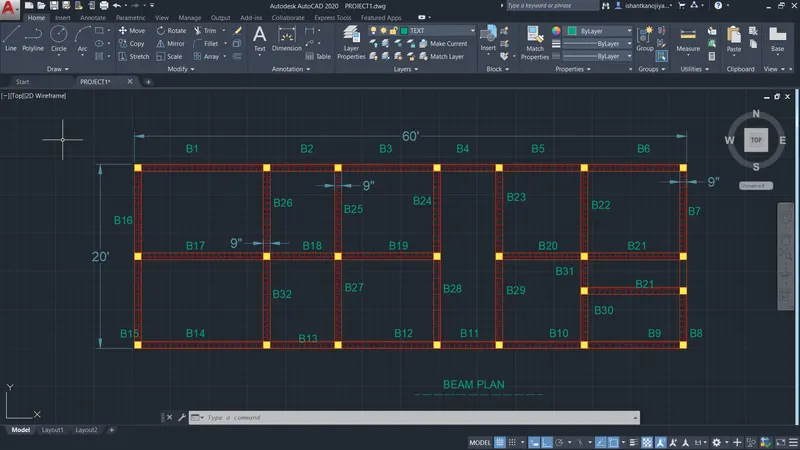
- The same procedure to follow the beam layout.
- Before to check the load acting on the beam, then to design the beam size.
- TYPE ,,D’ in command bar to give the size of the dimension and size of the arrows, changing tool command is DDIM.
- The dimension Color of the layer properties of Green.
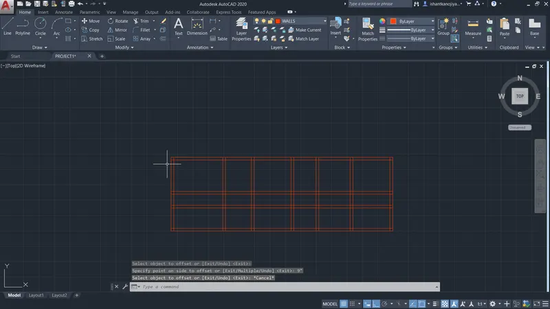
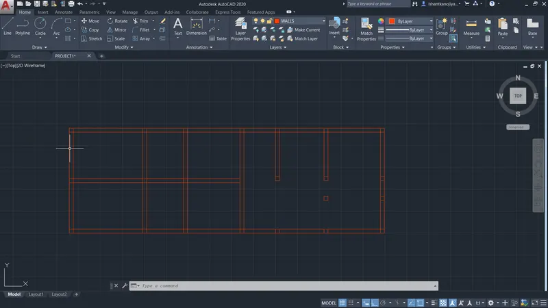
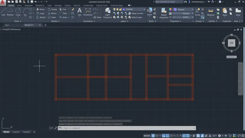
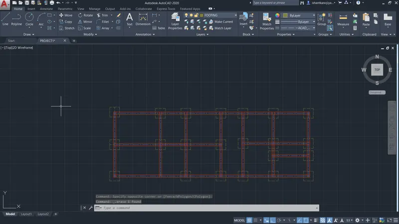
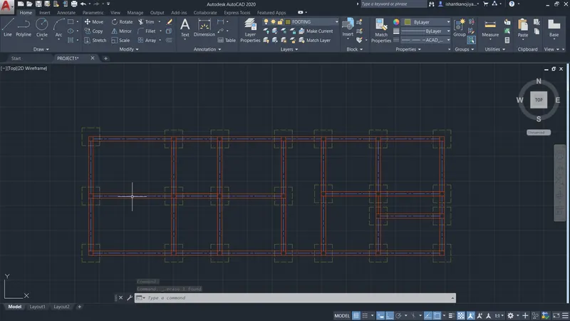
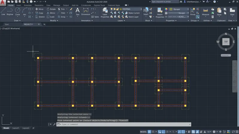
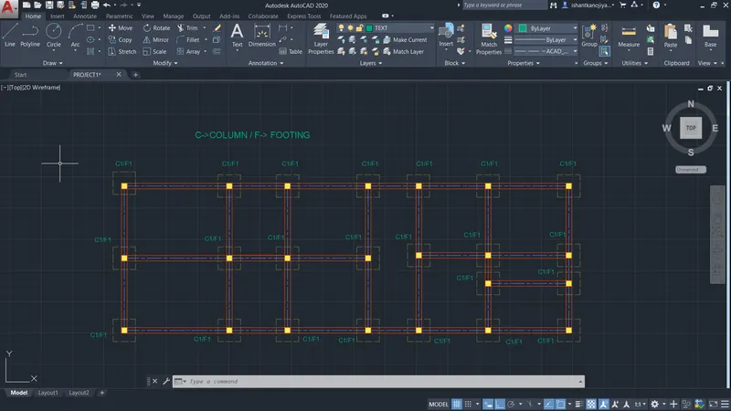
RESULT
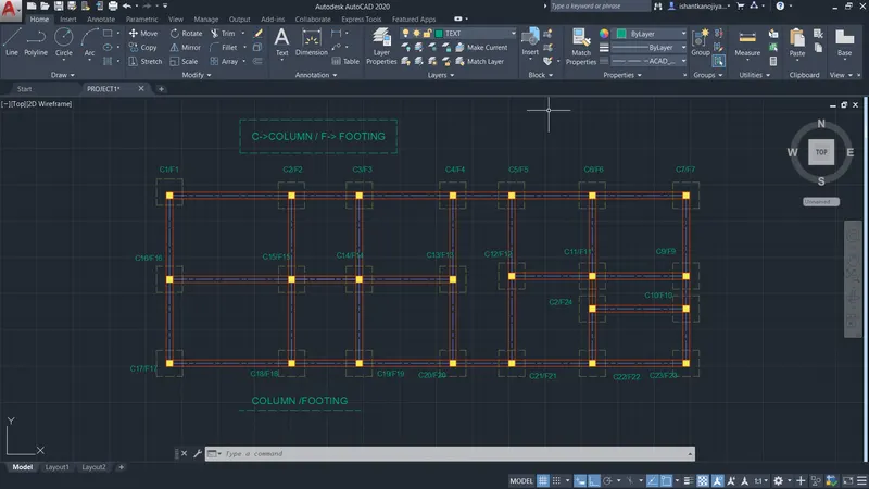
B. BEAMS
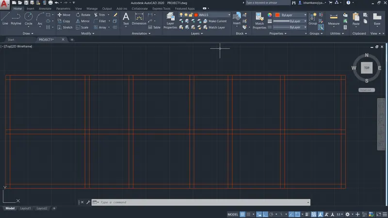
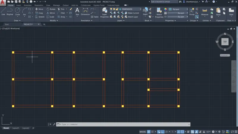
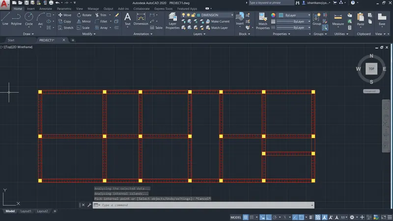
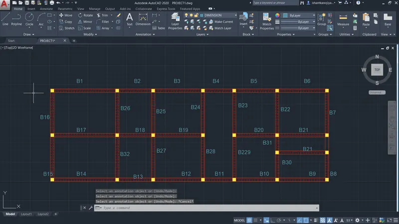
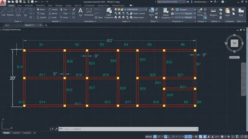
- SKETCH THE BEAMS
- USING LINES TOOS, OFFSET TOOL, TRIM TOOL,AND OTHES TOOLS
-
RESULT