Project 1 _Creating an Architectural plan for the provided plot size and develop relevant basic structural drawings
Aim: To draw the Architectural Drawing (Floor Plan, Elevations, and Sections) and Structural Drawing (Column, Beam, Footing Plan) for the plot size 60'x20' using AutoCAD.
Introduction: The Architectural and Structural drawings are drawn in AutoCAD using various tools / commands. The details to draw in AutoCAD are shown below:
Plot Size - 60' x 20'
Orientation - East Facing.
The plan is drawn with main door at the North-East and facing to north direction. The main gate is provided to east facing at North-East position.
The dimensions of the components of house are as follows
Walls
Thickness of main walls is taken as 9”
Internal wall thickness is taken as 4.5”
Columns and Beams
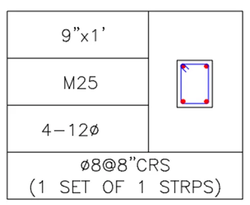
All the columns are of size 9”x18”
All the beams are of size 9”x12”
Doors
Dimension of Main door and entrance 4’x7’ with attached window
Dimension of doors of all bedrooms and Pooja room are 3’x7’
Dimension of doors of all toilets are 2’6”x7’
Windows
Windows in Living/Dining/Hall are taken as 6’x4’
Windows in all bedrooms are 4’x4’
Windows in Kitchen are taken as 4’x3’
Ventilators are taken as 2’x2’
Compound/Parapet wall
Height of compound wall is taken as 6’
Height of parapet is taken as 3’
Thickness of parapet/compound wall is 4.5”
Staircase
The Doglegged staircase is provided with 19 steps. 8 Steps in each flight and a midlanding is provided.
Thread and Raiser are taken as 10” and 6.6” respectively
The drawings are created in AutoCAD using XLine, line and polyline tool, the dimensions and text are provided with the use of layers. The procedure of drawing is explained and the final results are given.
Commands Used:
Units
Limits
Line
Polyline
Circle
Arc
Rectangle
Trim
Extend
Offset
Mirror
Rectangular Array
Hatch
Move
Rotate
Dimlinear
Dimstyle
Fillet
Linetype
Lineweight
Layers
Mtext
Multileader
Procedure:
Step 1
Type unit or UN in the command line and press enter
Set type of unit as Engineering and precision as 0’0”
In insertion scale set unit as millimeter.
Set upper limit and lower limit of the drawing
Step 2
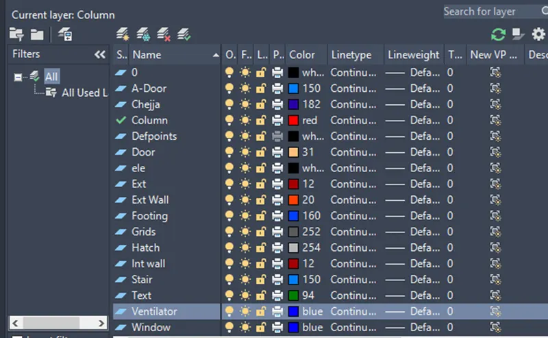
Type layer or LA in the command line and press enter
Create new layers as per requirement
Layers are created as follows
Step 3: Creating Site plan
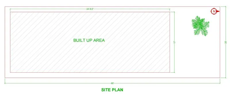
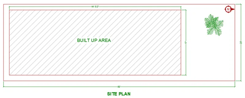
First, draw the plot area of size 60’x20’ with building area using the rectangle and line command with respect to the orientation of site.
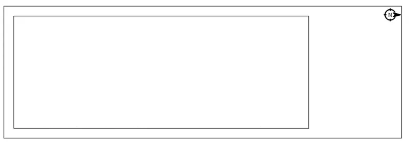
Hatch the built-up area and use dimension tool to measure the dimensions and assign the respective layers to the drawing
Step 4: Creating Ground floor plan
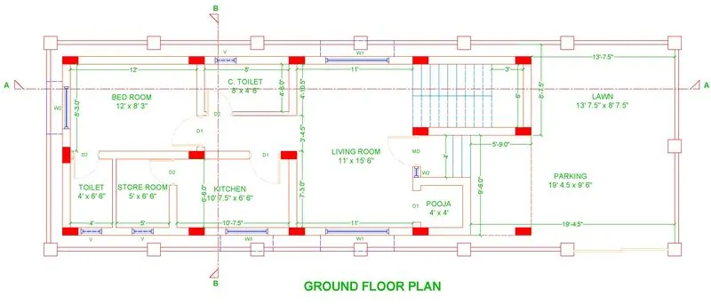
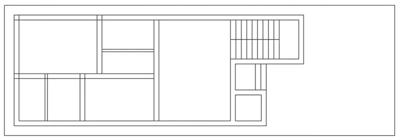
Draw a rectangle of dimensions 60’x20’
Provide front side offset of 14’ and all other side offset of 1.5’
And draw the exterior and interior walls for the respective rooms
Draw staircase with the room size of 10.5’ x 6’, the tread is 10” riser is 6.6” in ground floor
Trim the extra lines
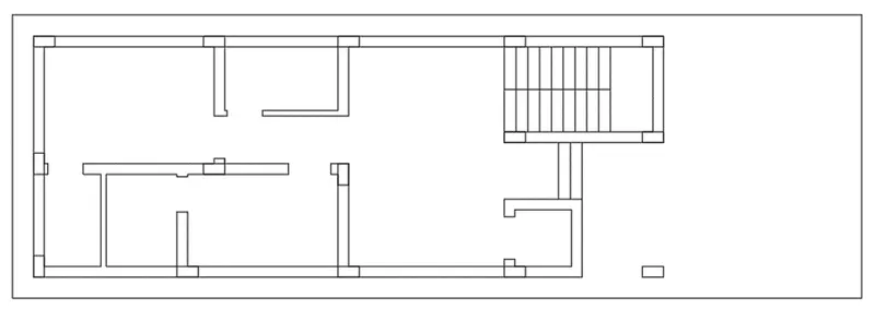
Place columns of 9”x18” for the respective positions
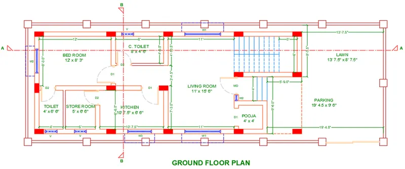
Provide the doors and windows for the respective dimensions and trim the extra lines
Hatch the necessary area, draw chejja, compound wall
Indicate the rooms using the single text command.
Provide dimensions for the given floor plan using the dimlinear command.
And also draw the section lines as given in the figure, and also indicate the doors and windows.
Using hatch command, dimension command and text command complete the floor plan
Step 5: Creating First floor plan
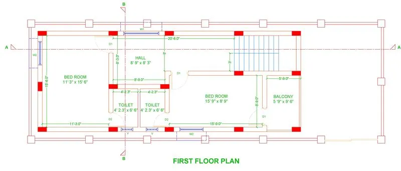
Draw a rectangle of dimensions 60’x20’
Provide front side offset of 14’ and all other side offset of 1.5’
And draw the exterior and interior walls for the respective rooms
Draw staircase with the room size of 10.5’ x 6’, the tread is 10” riser is 6.6” in first floor
Place columns of 9”x18” for the respective positions
Trim the extra lines
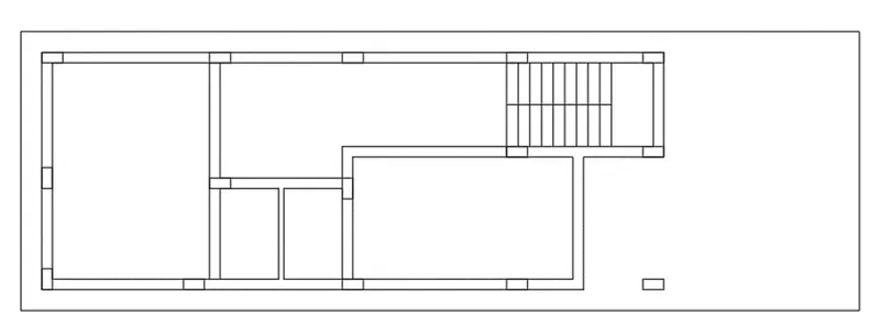
Provide the doors and windows for the respective dimensions and trim the extra lines
Hatch the necessary area, draw chejja, compound wall and assign the respective layers to the drawing.
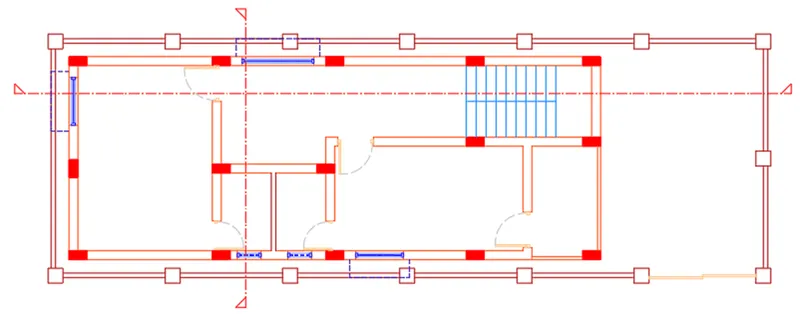
Indicate the rooms using the single text command.
Provide dimensions for the given floor plan using the dimlinear command.
And also draw the section lines as given in the figure, and also indicate the doors and windows.
Using hatch command, dimension command and text command complete the floor plan
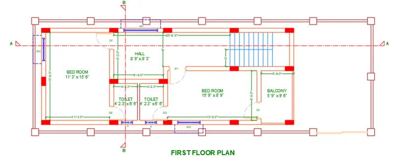
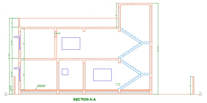
Step 6: Creating Section A-A
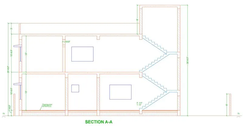
Draw the construction line from Section AA line in the plan to draw the section AA. Use copy tool to replicate construction line
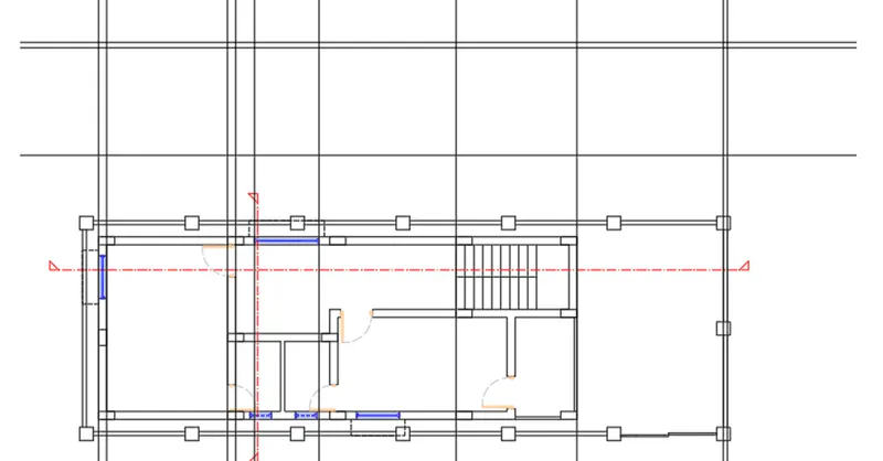
The inner wall thickness is 4.5” and outer wall thickness is 9”
Next, draw the construction line from first floor section and draw the windows in them requires to places in both the floors
Using the line command, offset command and trim command draw the section AA
Draw staircase with the room size of 10.5’ x 6’, the tread is 10” riser is 6.6” in first floor
Trim the extra lines
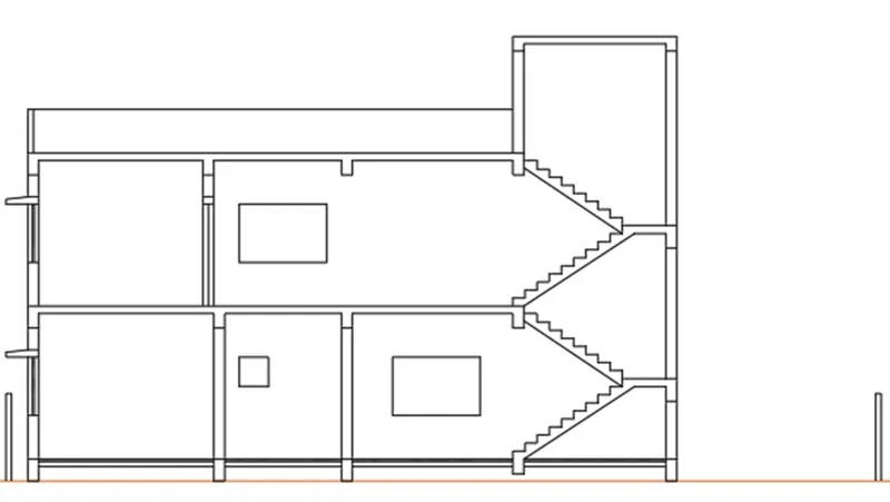
Indicate the necessary details using the single text and leader command.
Provide dimensions for the given floor plan using the dimlinear command.
Draw and indicate the doors and windows assign the respective layers to the drawing.
Using hatch command, dimension command and text command complete the Section AA
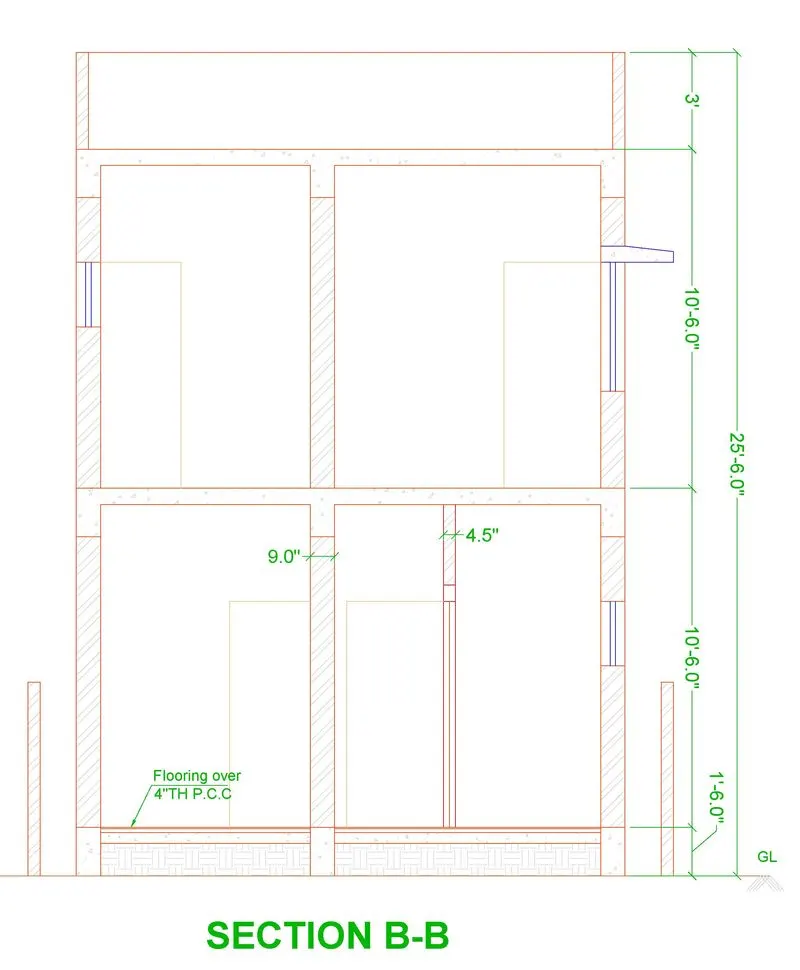
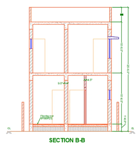
Step 7: Creating Section B-B
Draw the construction line from Section BB line in the plan to draw the section BB. Use copy tool to replicate construction line
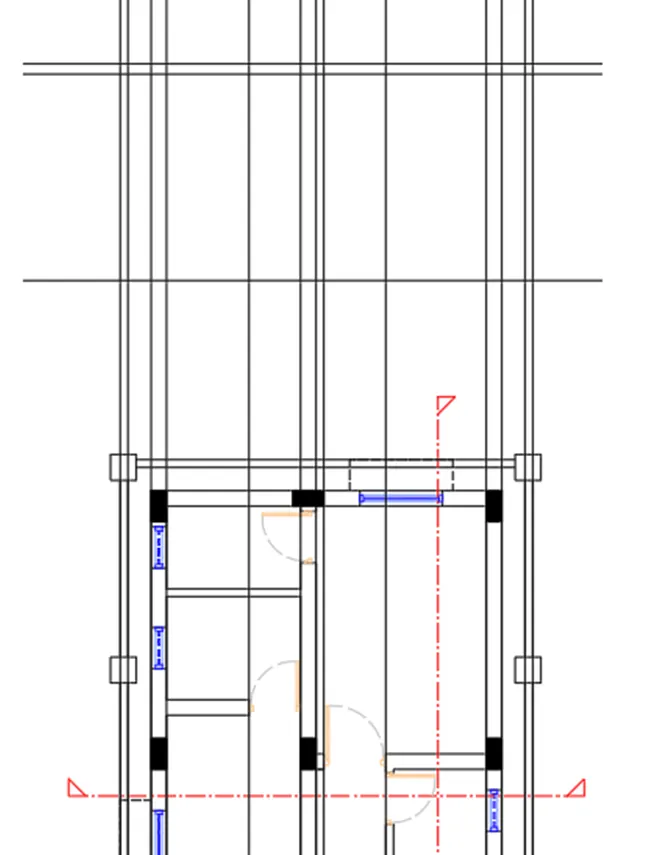
The inner wall thickness is 4.5” and outer wall thickness is 9”
Next, draw the construction line from first floor section and draw the windows in them requires to places in both the floors
Using the line command, offset command and trim command draw the section BB
Trim the extra lines
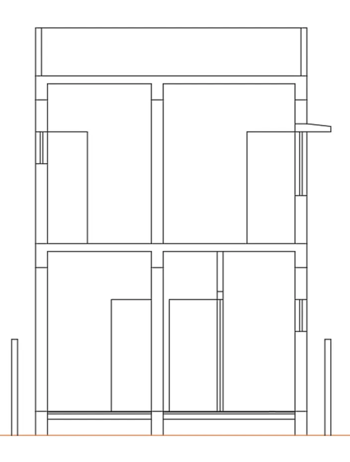
Indicate the necessary details using the single text and leader command.
Provide dimensions for the given floor plan using the dimlinear command.
Draw and indicate the doors and windows assign the respective layers to the drawing.
Using hatch command, dimension command and text command complete the Section BB
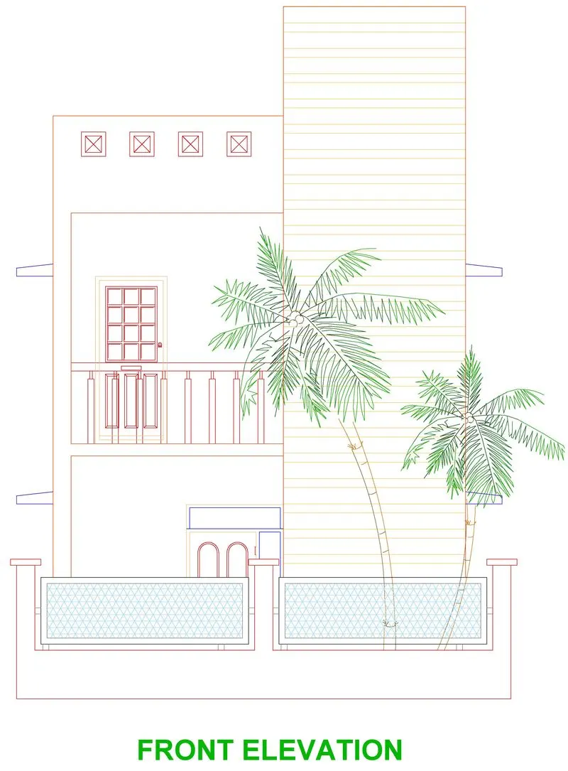
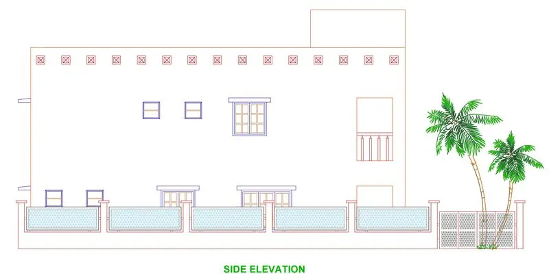
Step 8: Creating Front/Side Elevation
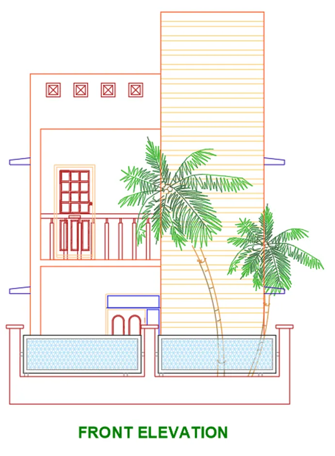
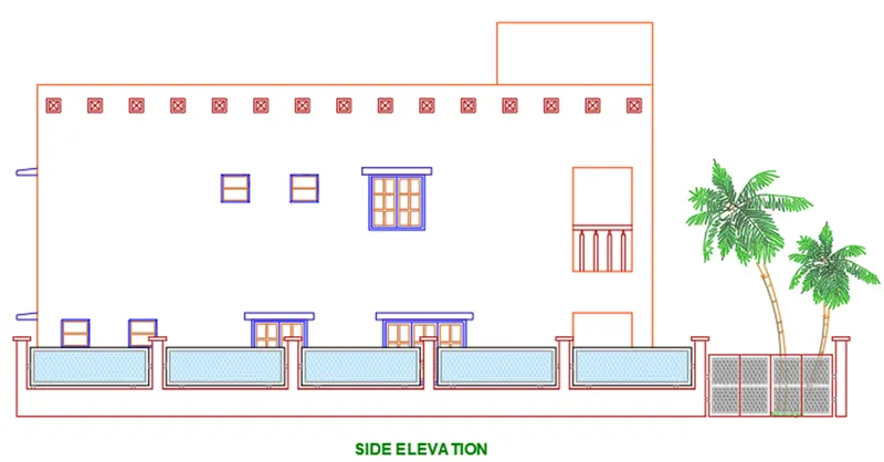
Project the construction line and draw elevation view with respect to front and side of plan using draw tools.
Provided windows as per the plan, chajja as per plan and door as per plan.
Provided lintel beam over the windows, doors.
Provided Parapet wall.
Using Hatch command, and adjusted the scale for better visibility.
Using Hatch command, I have filled parapet wall with SOLID and adjusted the scale for better visibility.
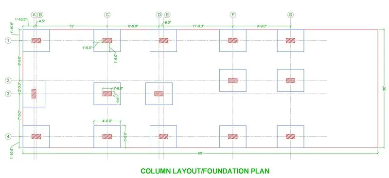
Step 9: Creating Column/Footing layout
Turn off all the layers except the column layer and boundary layer in the layer properties.
Select the copy tool by typing CO or COPY in the command box.
Select all the columns from the building plan and copy them to a different location as shown in the figure below.
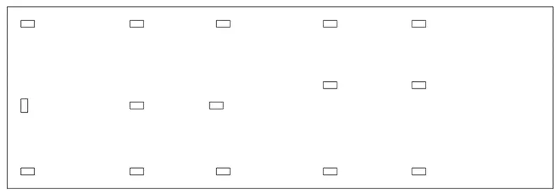
Select the Construction line tool by typing XL or XLine in the command box.
Select the line type and give scale as per requirement.
Draw lines through the midpoint of the columns in the horizontal and vertical directions as shown in the figure below.
Select the Trim tool by typing TR or Trim in the command box.
Trim the unnecessary lines and press Esc to cancel the trim command.
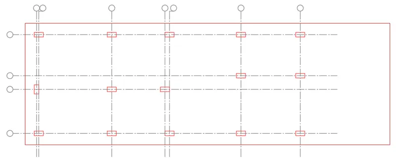
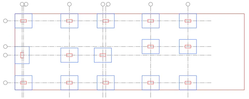
Next, draw the footing with the required dimensions.
In this case the column size as 9" x 18".
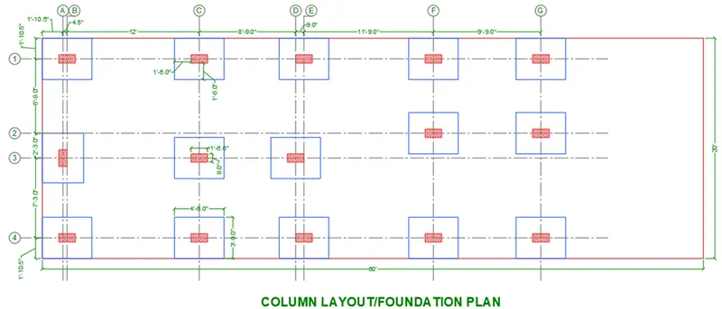
Next we do the offset of 1'-6" horizontally and vertically from the columns to form the footings.
Then draw the footing layout with required dimensions.
Select the Dimension tool by typing DIM in the command box.
Select the first point and the second point of the object to measure. Repeat for all the objects to be measured.
Enter DS in the command box to open the dimension style manager dialog.
Modify the dimensions as per the requirement.
Change the color of the dimension and extension line as per the requirement.
Give dimensions and text as per the drawing and requirement using the Mtext command and Dimension Command.
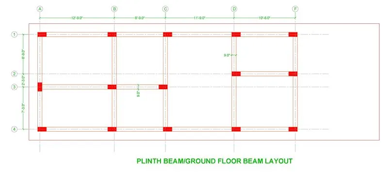
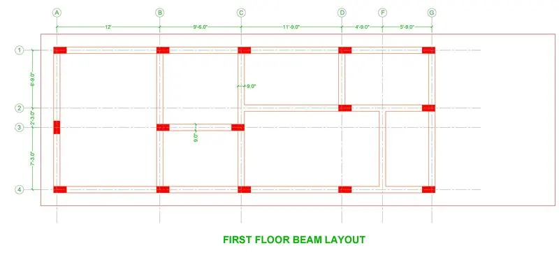
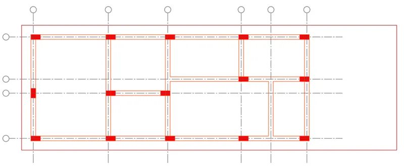
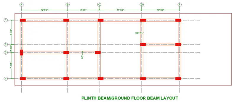
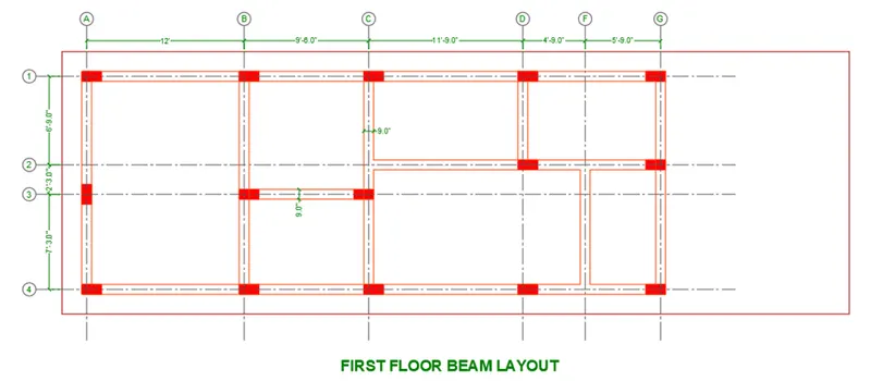
Step 10: Creating Beam layout
Turn off all the layers except the column layer and boundary layer in the layer properties.
Select the copy tool by typing CO or COPY in the command box.
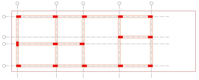
Select all the columns from the building plan and copy them to a different location as shown in the figure below.
Involve polyline tool by typing PL in command line
Draw the lines to connect the beams to columns in both the floors
Select the Construction line tool by typing XL or XLine in the command box.
Select the line type and give scale as per requirement.
Draw lines through the midpoint of the beams in the horizontal and vertical directions as shown in the figure below.
Select the Trim tool by typing TR or Trim in the command box.
Trim the unnecessary lines and press Esc to cancel the trim command.
Select the Dimension tool by typing DIM in the command box.
Select the first point and the second point of the object to measure. Repeat for all the objects to be measured.
Enter DS in the command box to open the dimension style manager dialog.
Modify the dimensions as per the requirement.
Change the color of the dimension and extension line as per the requirement.
Give dimensions and text as per the drawing and requirement using the Mtext command and Dimension Command.
COLUMN SCHEDULE:
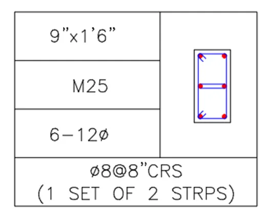
BEAM SCHEDULE:
RESULT: