Project 1 _Creating an Architectural plan for the provided plot size and develop relevant basic structural drawings
AIM: TO Design and Draft a layout of a residential building.
INTRODUCTION:
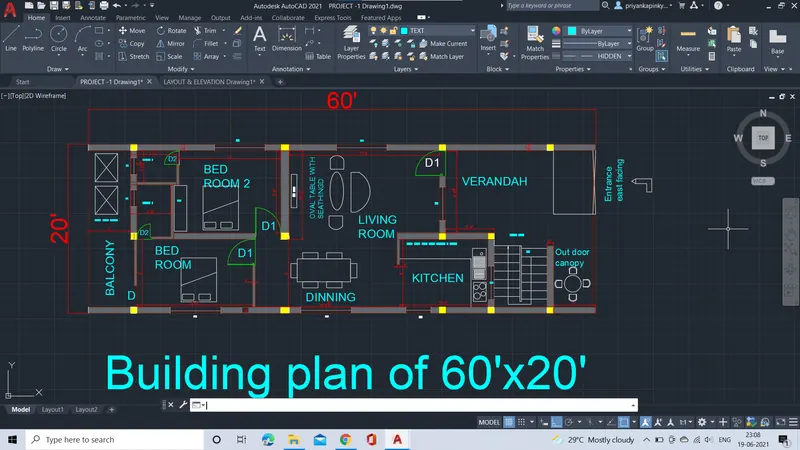
- In order to design and draft a layout of a residential building of plot size 60'x20' with orientation east facing.
- The commands used are XL line (construction line), line command, rectangle command, circle command and other drafting commands such as offset, trim, extend, join,text, dimstyle and other such tools.
- The built up area was 40'x20' with 2BHK and with setbacks 5'( back) for balcony with lawn and 10'(front) for setout and verandah.
- The details of the structural members such as column, beam and footings were
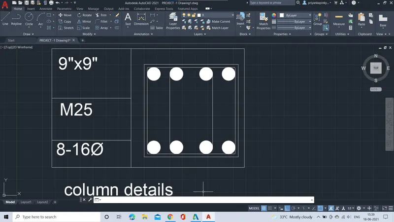
- Column details are size- 9"x9",with grade M25 and 8 no's with16mm dia bars.
- Beam with size 9"x12".
- Footing details are simple footing(square) with size 4'x4' , height 500mm ~2'and 10 no's 10mm dia bars in bothways provided cover of 50mm~2".
- Thickness of the wall for exterior wall- 9 inches and interior wall - 4 inch.
PROCEDURE:
- First set the Drawing units such as feets and inches.
- Set the limits of the sheet such as left corner as (0',0')and right corner as( 400',400').
- Then zoom the drawing sheet and start drafting the plan.
- In order to design a residential building , the first and most important is ideal placing of columns.
- To place the columns, First draw the grid lines in order to form a grid layout.
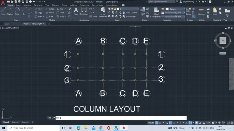
- Using XL command draw the vertical and horizontal lines in the plot area.
- Where the both vertical and horizntal lines intersect each other, draw the columns.
- The columns of size 9"x9" should be drafted using offset command. and trim the unnecessary segments.
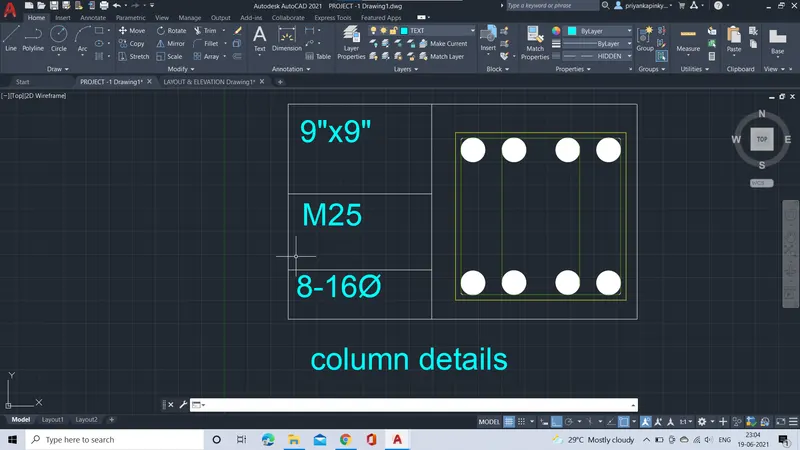
- The columns must be placed at center to center distance of the specifed spacing distance.
- Draw the footings using rectangle command, specify the dimensions such as length as 4' and width as 4'.
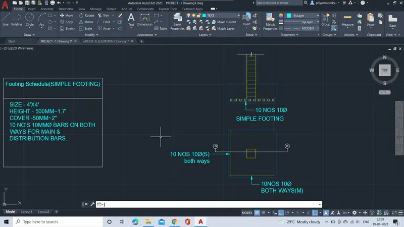
- Using Copy command, copy the footings and place around the columns.
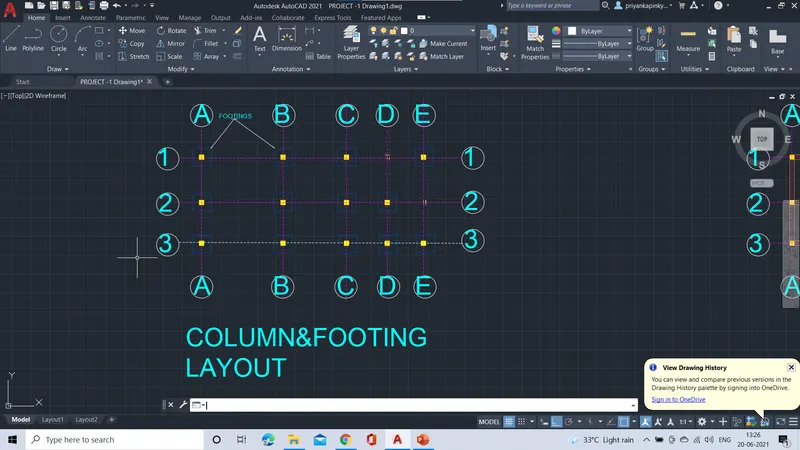
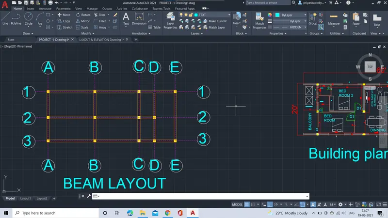
- Draw the beam layout using the line command.
- Copy the grid layout, using line command draw the lines connecting the all columns through out layout and then with offset of 9" draw line with reference to previously draw lines which forms the beam layout.
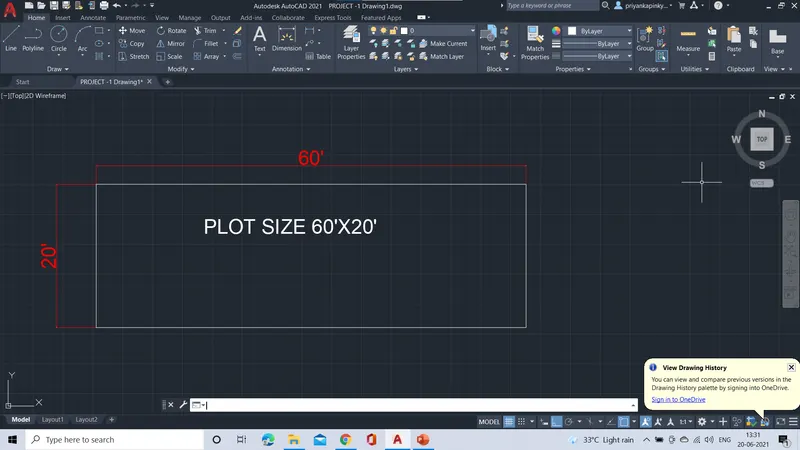
- Then draw the plot size of 60'x20' using line command.
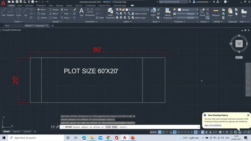
- Firstly offset the set backs of the plot size of 5'backside and 10' front.
- Then start drafting the rooms in the built up area.
- Using Line command , draw the outer wall using line and offset the line of 9" which is thickness of the wall.
- Using the offsite command , draw the inner walls.
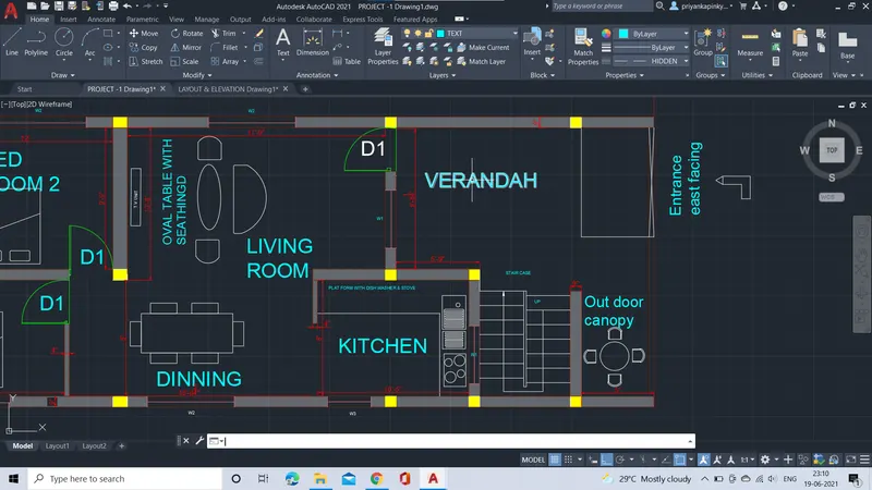
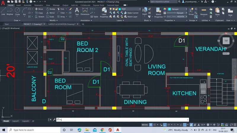
- Draw the bed room 1 with dimensions 13'8"x 8' using line command and bed room 2 of 12'x 9'9" with toilets of 4'5"x5'3" for both bed rooms.
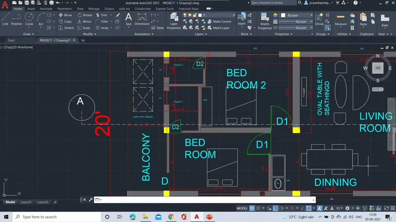
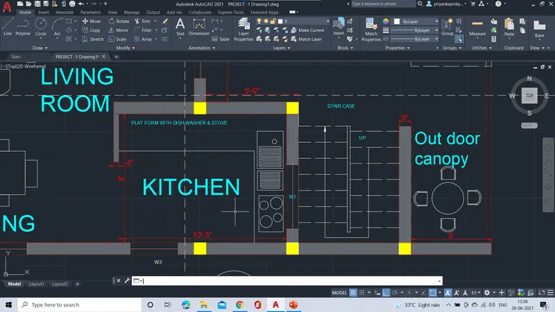
- Then draft the kitchen(10'-5"x8') using the line and offset cmmands.
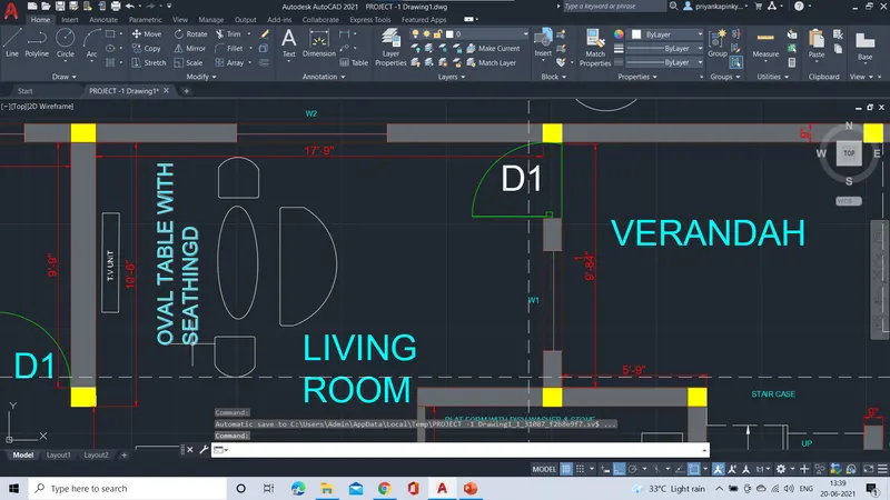
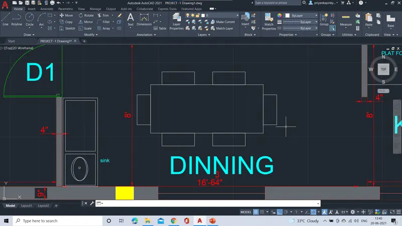
- In similar draw the living room ( 17'-9"x10'-6") and dining hall ( 16'3'x8') using line command.
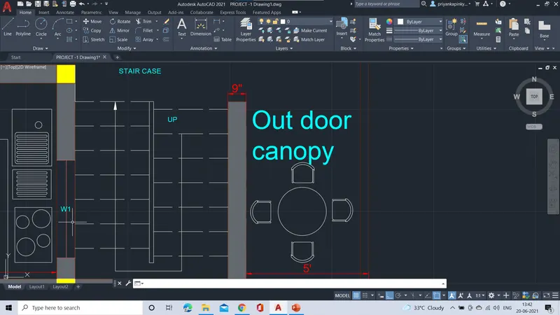
- Then draft stairs of thread -1'9" and rise -1' using line command of line type -hidden dash.
- Using line command and other drafting tools such as offset, trim ,cricle, fillet, rectangle etc, Draw the furniture and place it respectively.
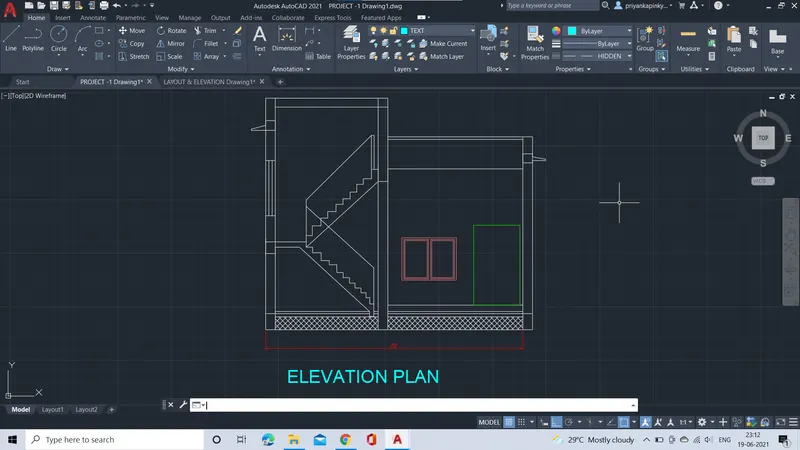
- Then sketch the elevation of the plan using line command and offset command.
- In elevation, the front view of the plan can be shown that includes door, window and stair case, and front walls.
- Then finaly specify all the items into layers.
- LAYERS: Layers are the set of different lays in one page. It is one of the most standard settings. Every building element can separately shown under the layers, we can set different colours for different items by managing the layers and be easly controlable and easy identifiation of elements.Layers can also be used for modification of layers.
- We have open layers by shortcut method through slecting menu bar by clicking>> layer properties or by Ribbon tab or through command prompt - LAYER.
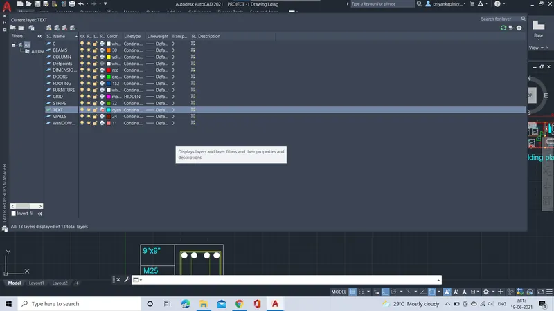
- Open layerpropers and create the new layer and name the layer as walls, columns, footings, text, dimensions and all the building elements can be formed as separate layer by creating the new layer.
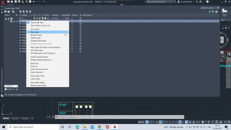
- Then select all the walls and click on the>> wall layer then all walls will be specified in wall layer as usually make all the building elements .
RESULT:
PLOT SIZE:
GRID LAYOUT OF COLUMNS AND FOOTINGS( structural drawings):
BEAM LAYOUT:
BUILDING PLAN: 2BHK( Architectural drawings)
ELEVATION:
DEATAILS OF THE BUILDING ELEMENTS:
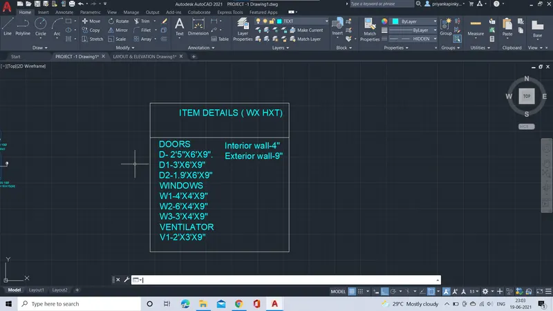
THERE FORE THE RESIDENTIAL BUILDING PLAN OF 2BHK HAS BEEN DRAFTED NEATLY WITH ABOVE MENTION DETALS.