Project 1_Comparative study of different storey buildings for Seismic forces
Comparative Study of Different Story Buildings for Seismic Forces
Aim: To model and analyse the buildings with different design parameters having different number of floors in ETABS and compare the results to understsnd the factors influencing the dynamic characteristics of building, time period of building and mode shape of building.
Introduction:
The structural configuration of the building plays a major role in determining the overall response during an earthquake. Different building geometries behave differently when induced by the same seismic forces. Hence, it is very important to properly understand the response of buildings related to their structural configurations for a safer design approach.
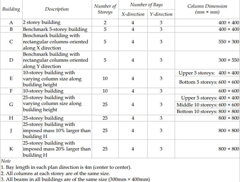
Therefore in this project, 10 different buildings with different parameters having different number of floors were modeled using ETABS. The models were analyzed and the results are then compared to understand the factors influencing the dynamic characteristics of building, time period of building and mode shape of building.
The below are the parameters of the building
Procedure:
BUILDING A
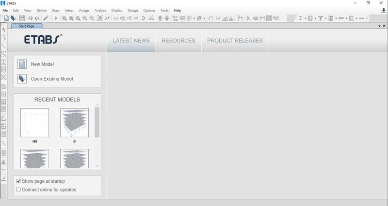
- Open ETABS software
- Click on New Model in the ETABS start
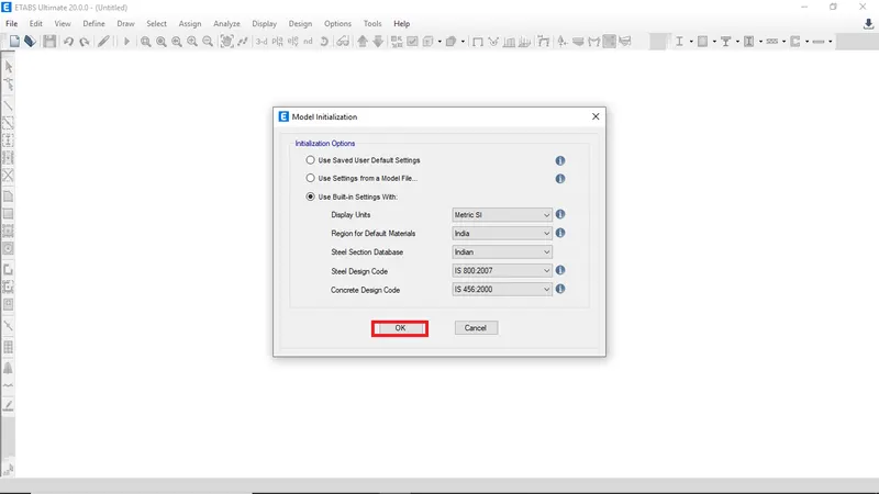
- Select Use Built in Setting from Modal Initialization dialog box
- Chose display unit as METRIC SI
- Region for default material as INDIA
- Steel selection database INDIAN
- Steel design code IS-800:2007
- Concrete design code IS-456:2000 then enter
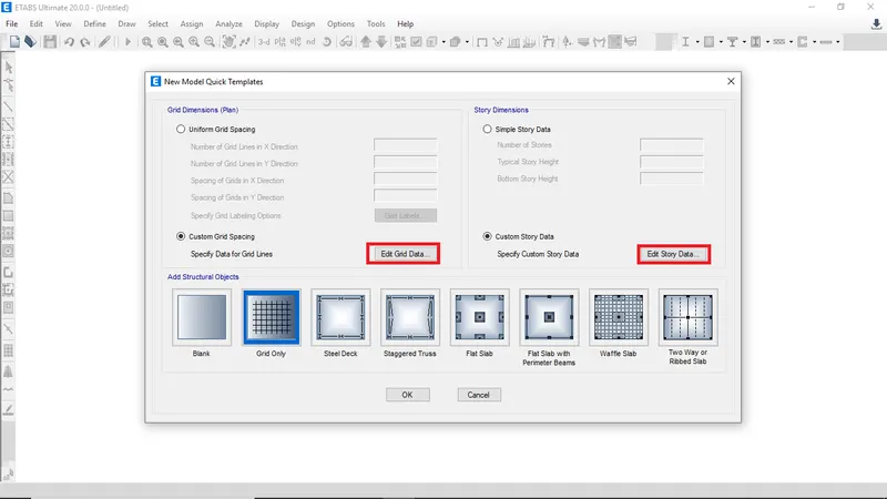
- Click on Edit grid data and Edit story data to define the grids and stories according to the given dimensions of the building
-
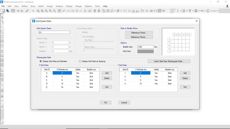
Enter the grid data along the X and Y direction
-
To add more number of grids in any direction click on add and specify the ordinate distance
-
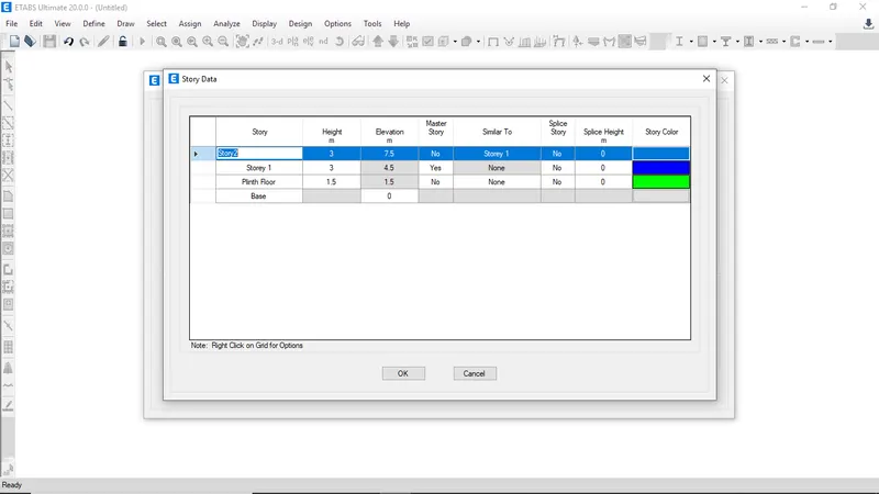
Building A has 2 story rename the story name and delete the extra story
-
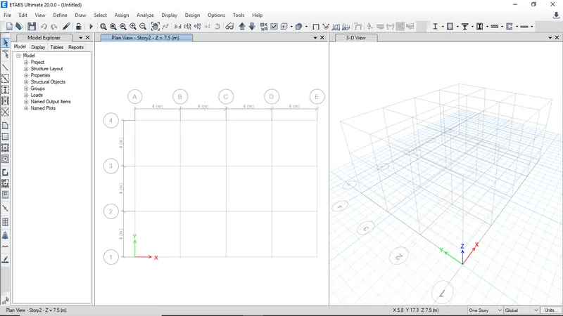
The grids and story were created for building A according the gived data
-
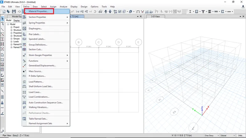
Select material properties from define to define the different materilal properties
-
Click on add to add new material property
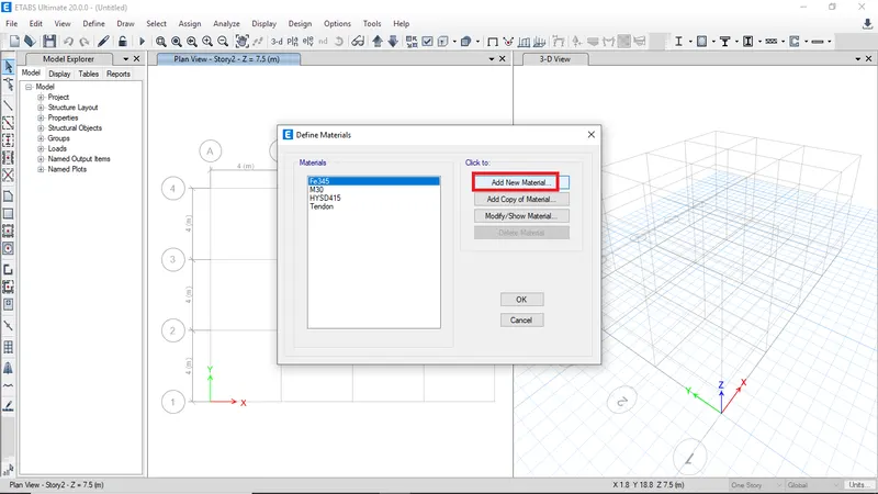
-
Define M30 concrete with the respective properties
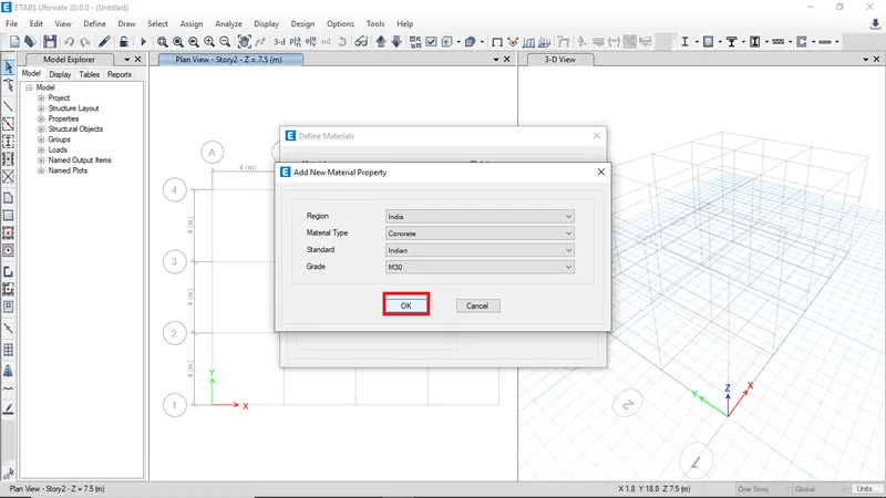
-
Click OK to ccreate material with the following material properties
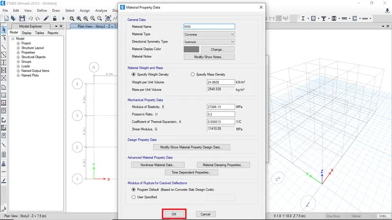
-
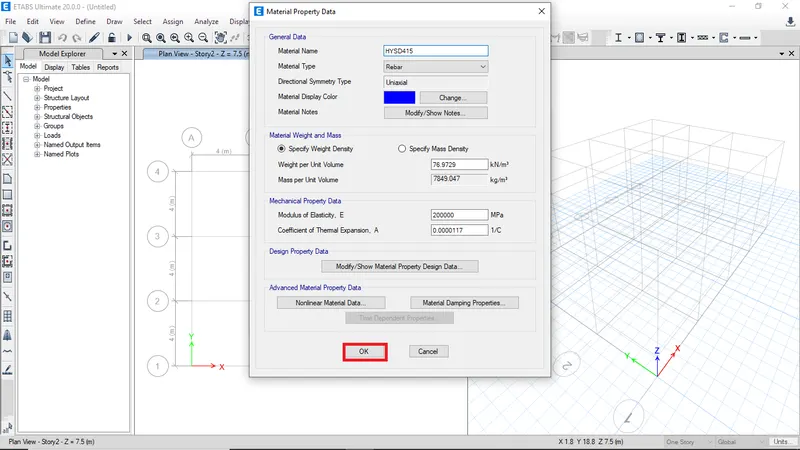
Define the Fe415 steel with the following material properties
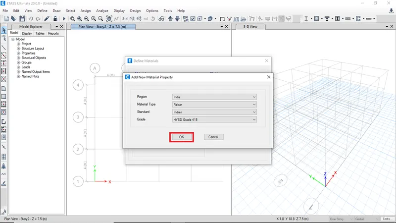
-
Click OK to ccreate material with the following material properties
-
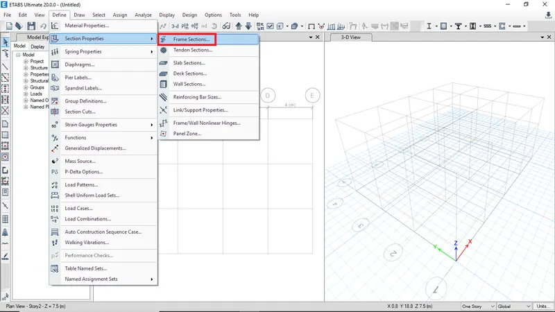
Define frame sections For building A by clicking on section properties
-
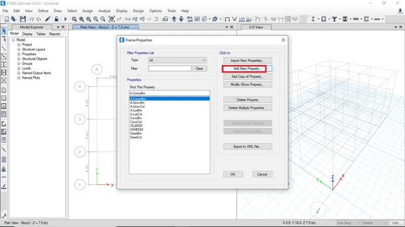
Click on Add new property to define new frame property
-
To define beam property for building A click on add new property
-
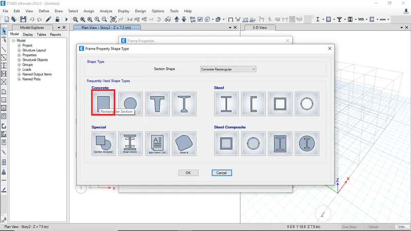
Then select rectangular section
-
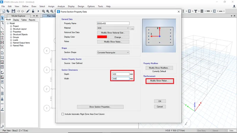
Provide property name as B300x400
-
Then close M30as material
-
Enter section dimensions then click on modify rebar data
-
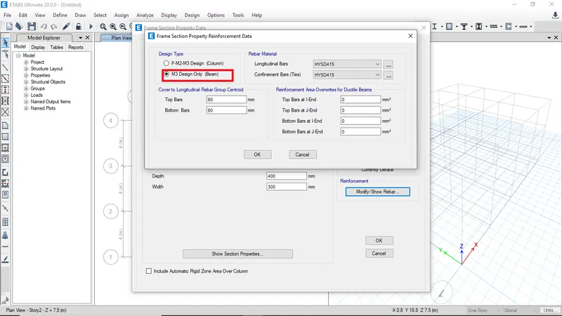
Select Beam design
-
Click Ok to finish and save section property
-
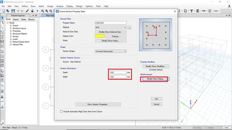
To create column property follow the same steps as of beam
-
Give property name as C400x400
-
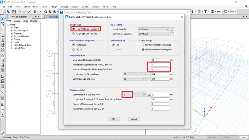
In the modify rebar select column design and enter the number of bars along the face direction
-
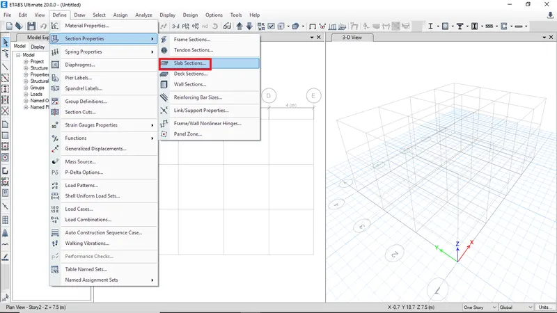
To define the slab properties click on define the select section properties theb select slab sections
-
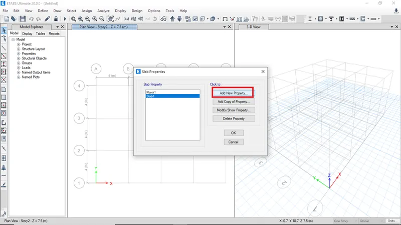
Click on add new property
-
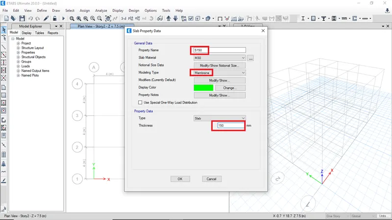
Enter property name and select modelling type as membrane
-
Enter the slab thickness as 150 mm
-
Then click ok to finish
-
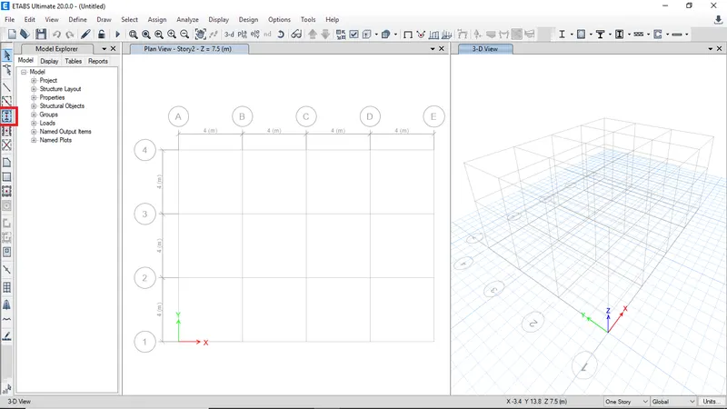
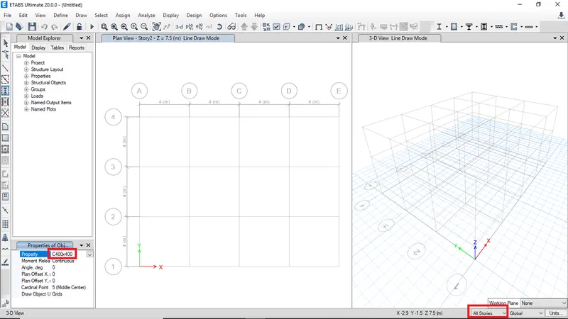
To draw columns click on quick draw columns
-
Then select column proprty from the dropdown
-
And make sure to select all stories
-
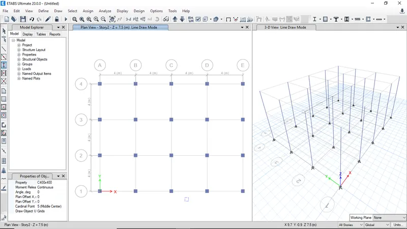
Draw columns at grid intersection
-
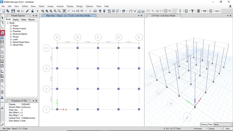
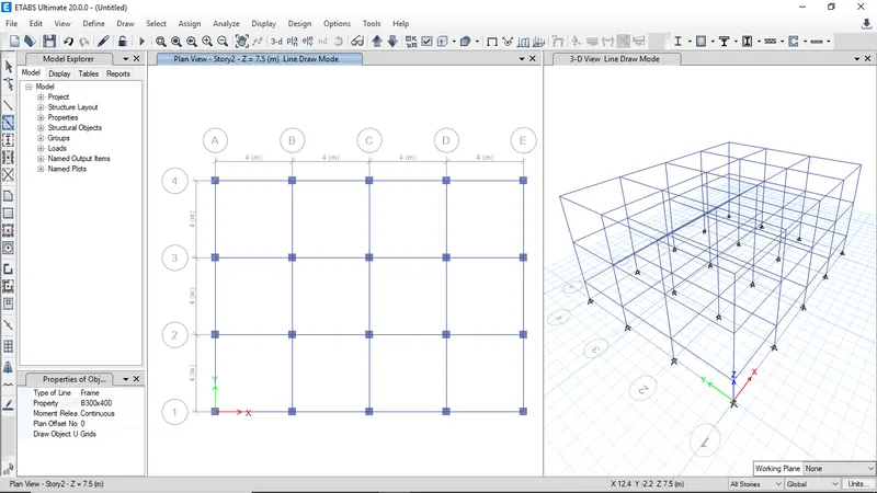
Click on quick draw beams to draw beams
-
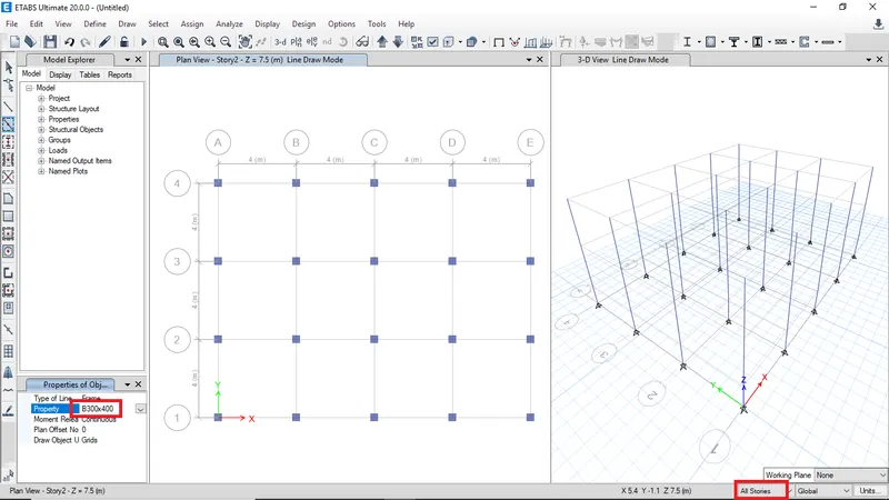
Select the beam property
-
Draw the beams along the grids
-
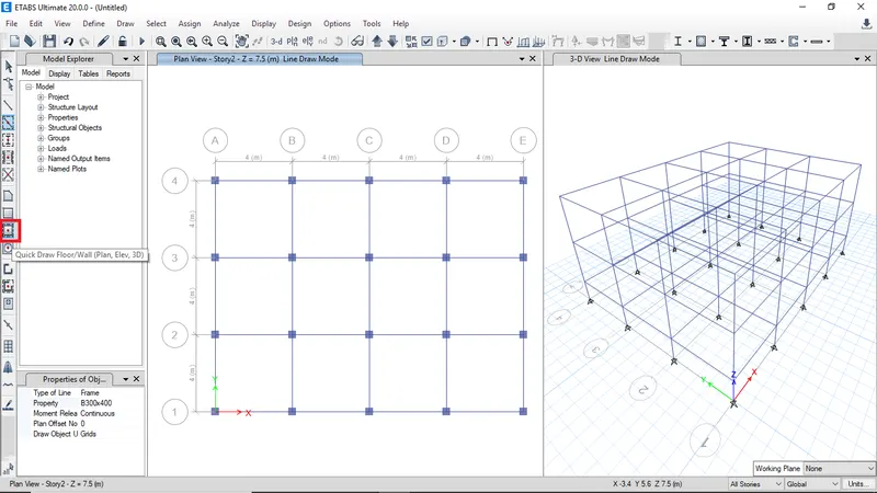
Click on Quick draw slab to draw slabs
-
Select slab property and switch to similar stories
-
click on grid boundaries to draw slab

-
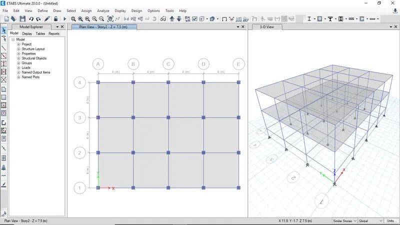
Plan and 3D model of Building A after drawing columns, beams and slabs
-
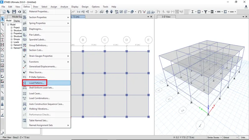
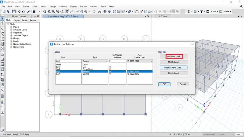
Click on define then select load pattern to create loads
-
Define load and select IS code then click add to define loads
-
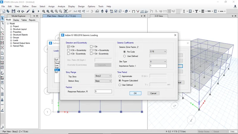
Define EqX load and select the zone factor and site type according to given parameters
-
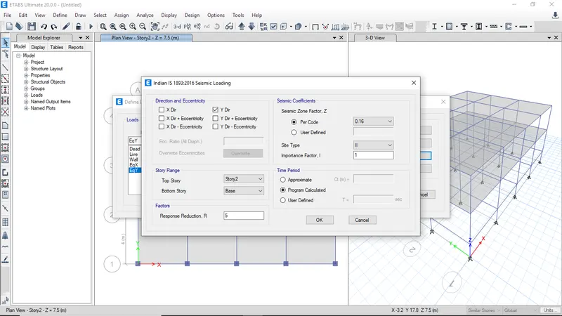
Define EqY load and select the zone factor and site type according to given parameters
-
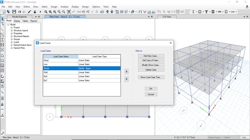
Check the load cases
-
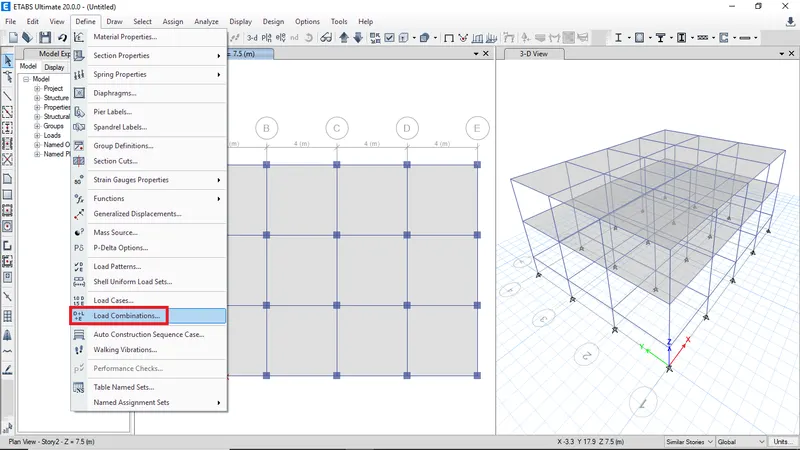
Click on load combination to define load combinations
-
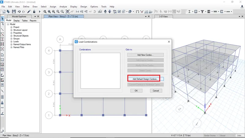
Click on add default design combos to create load combinations by ETABS
-
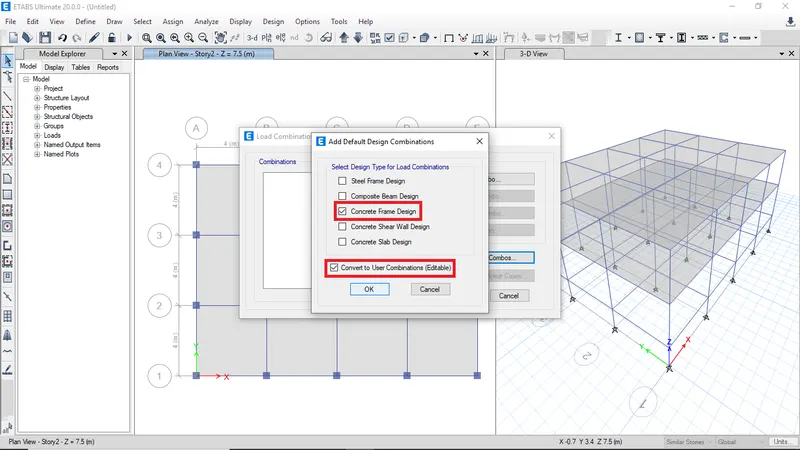
Select concrete frame design then click ok
-
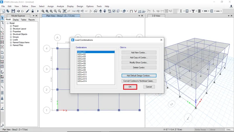
After creating load combinations click ok
-
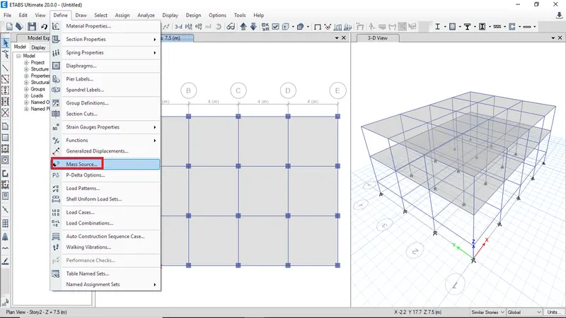
To define mass source click mass source from define menu
-
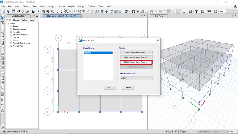
Click on modify mass source to edit mass source
-
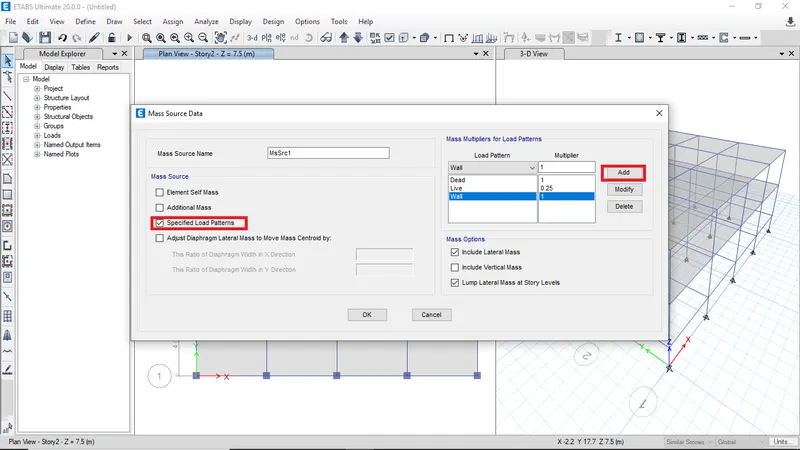
Select only specified load patterns and add the load patterns with the respective multiplier
-
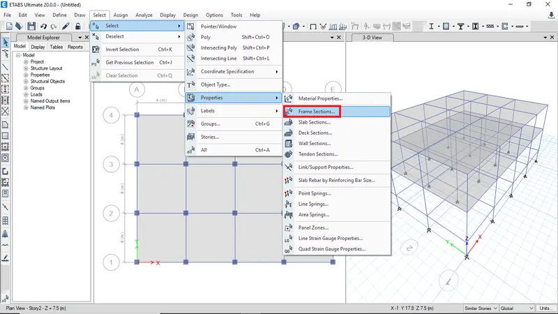
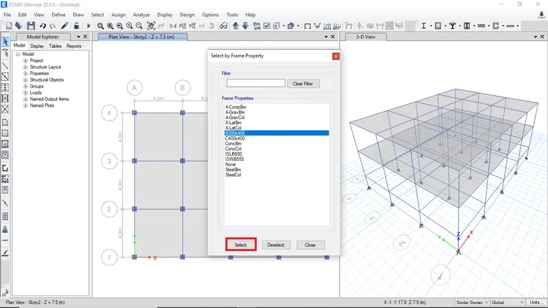
Select the frame section to assign the load pattern
-
Click on beams B300x400 then click on select
-
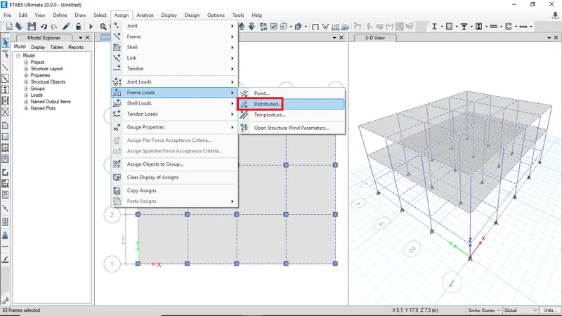
Goto assign frame loads then select didtributed load to assign wall load on beams
-
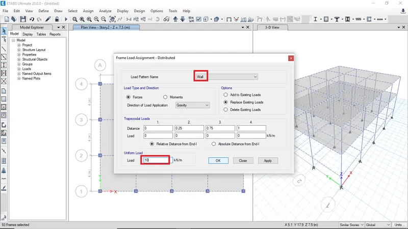
Select wall load and enter load value as 10 kN/m then click ok
-
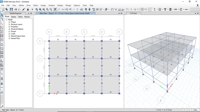
The assign loads will be visible
-
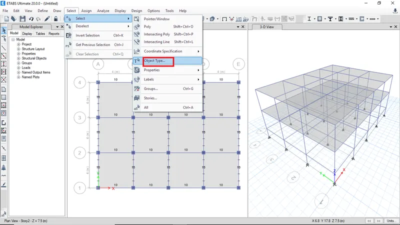
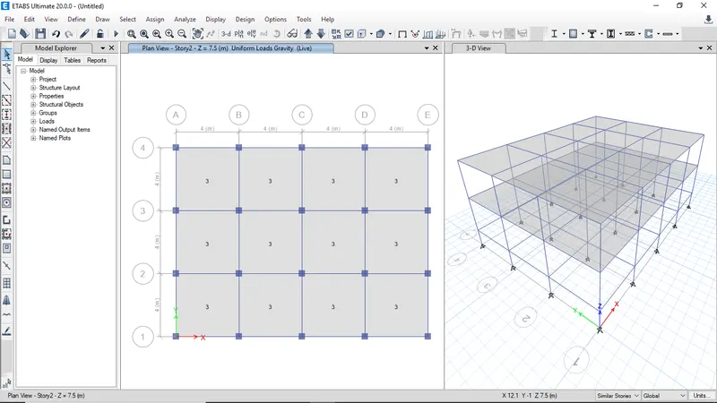
Select the slabs to assign the live load on slan and to assign diaphragms
-
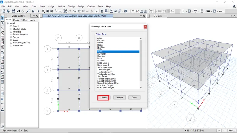
Click on floor then click on select to select he slabs
-
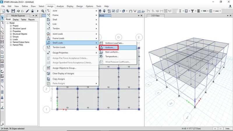
Select shell loads the click on unifoem load
-
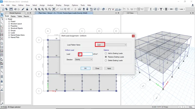
Select live load then enter the load value as 3 kN/m2
-
The live load is assigned to slabs
-
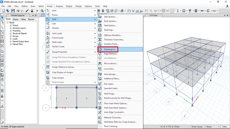
The to assign the diaphragms select the slabs
-
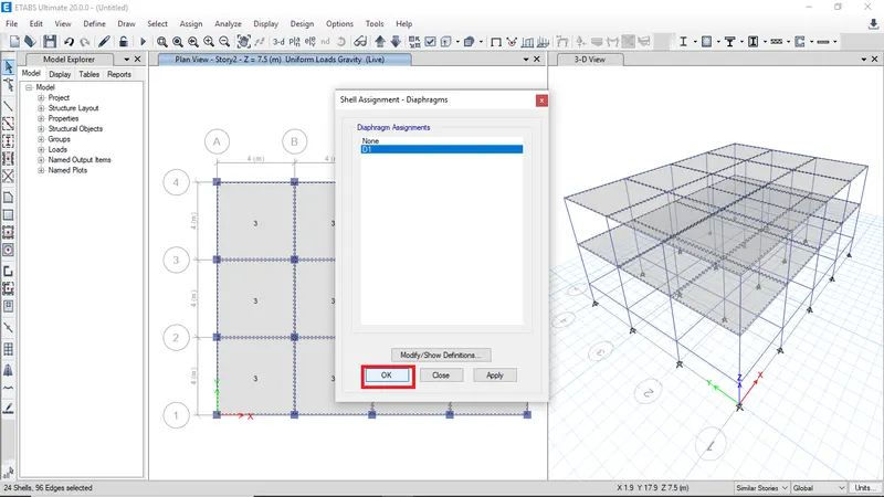
Select D1 click ok to assign
-
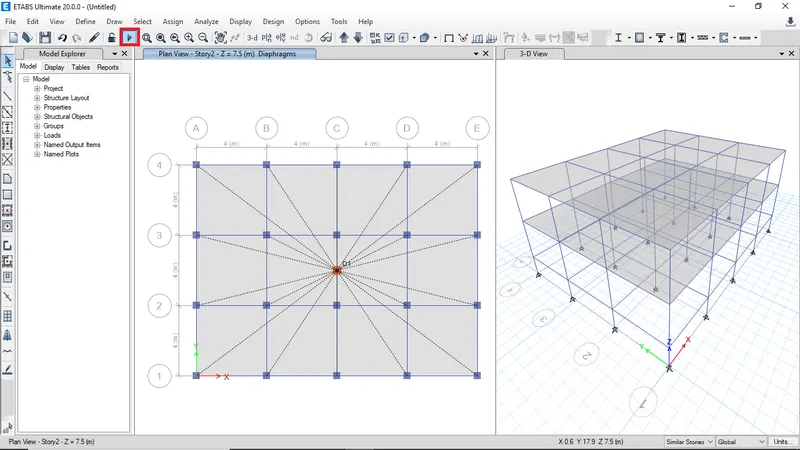
Click run analysis
-
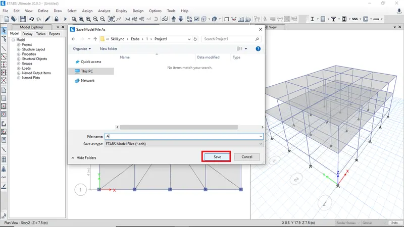
Enter model name as A then click save
-
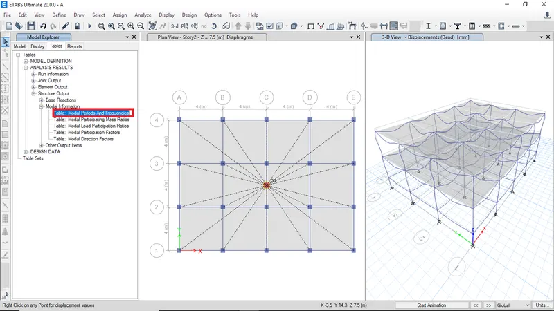
After analysis goto tables and click on modal periods and frequenclies
-
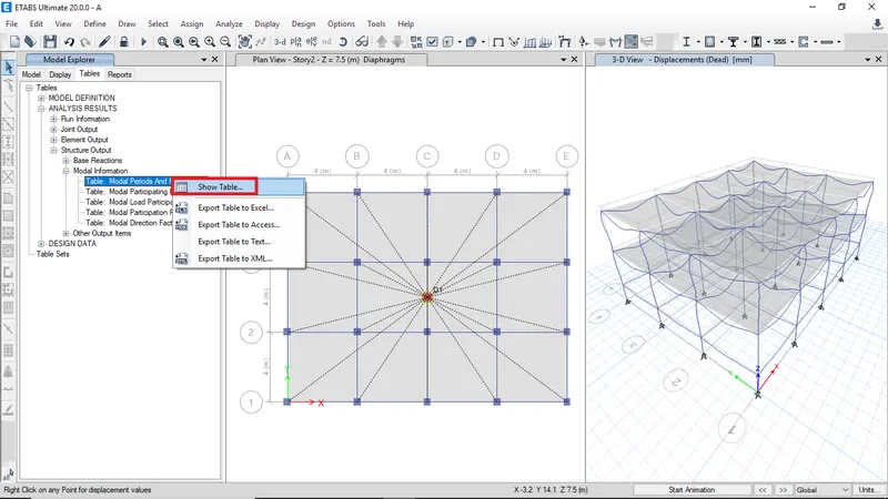
Right click and open table
-
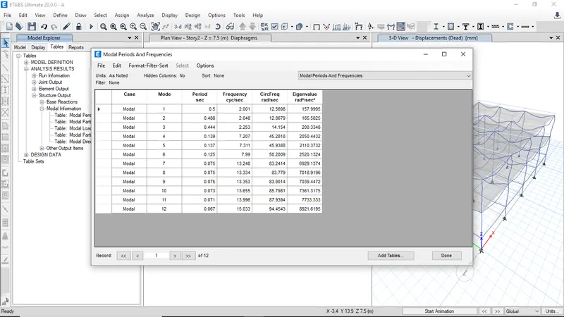
The modal periods and frequencies for building A
BUILDING B - The Building B has same parameters as Building A but building B has 3 more extra stories
-
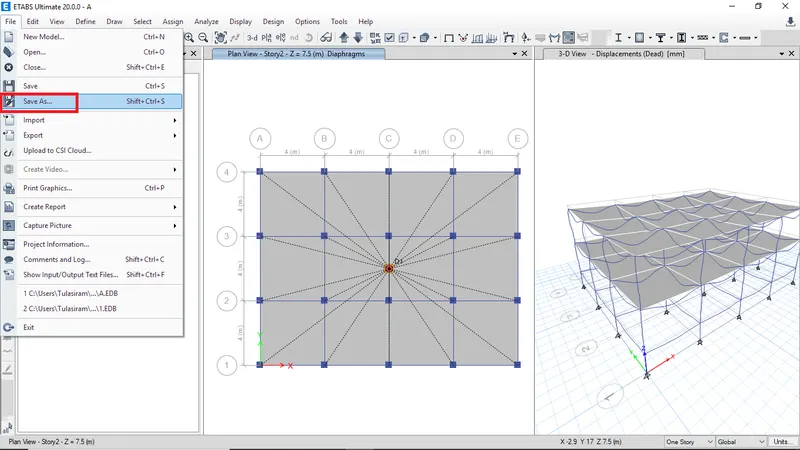
Goto file then click on save as to continue model
-
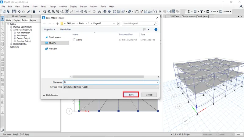
Enter the file name as B then click save
-
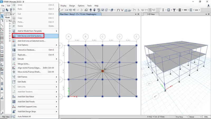
To add more stories click on edit stories and grid systems
-
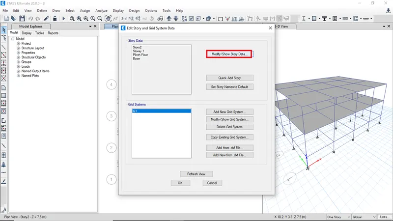
Click on modify to add more stories
-
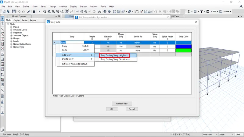
Right click and select keep exixting storey heights
-
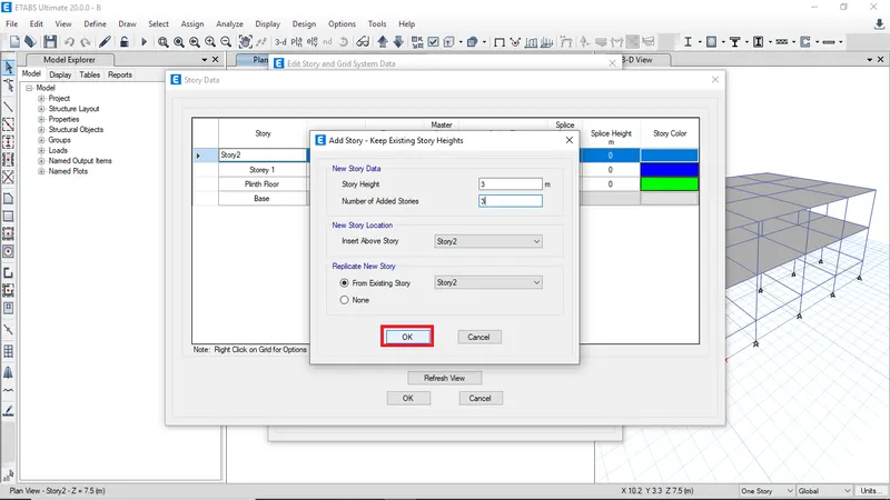
Enter the number of added stories as 3
-
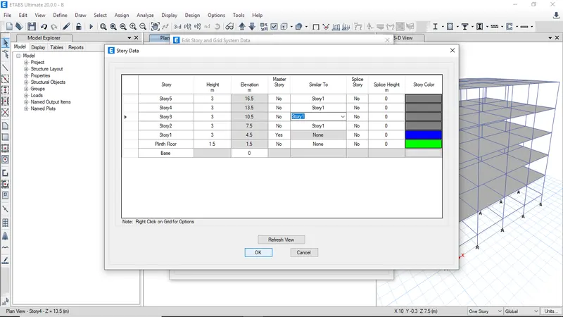
Select the similar and master storey then click ok
-
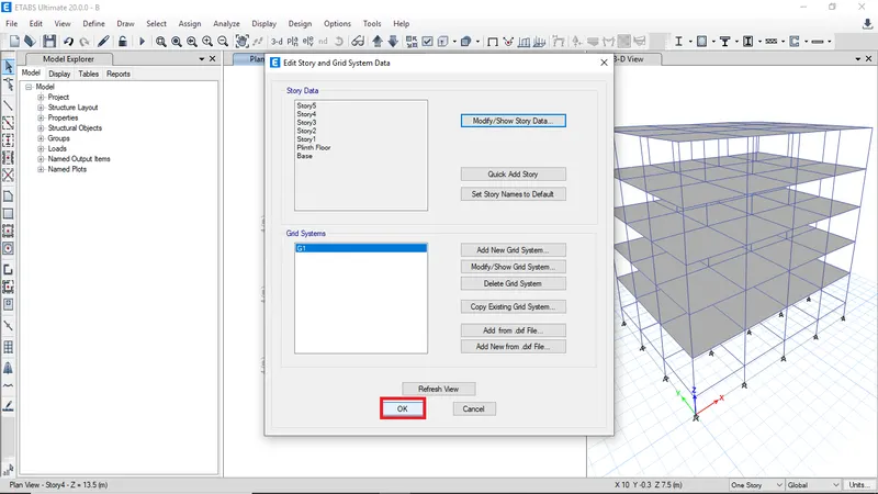
After adding stories click ok
-
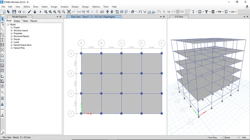
The added stories will be reflect in the model
-
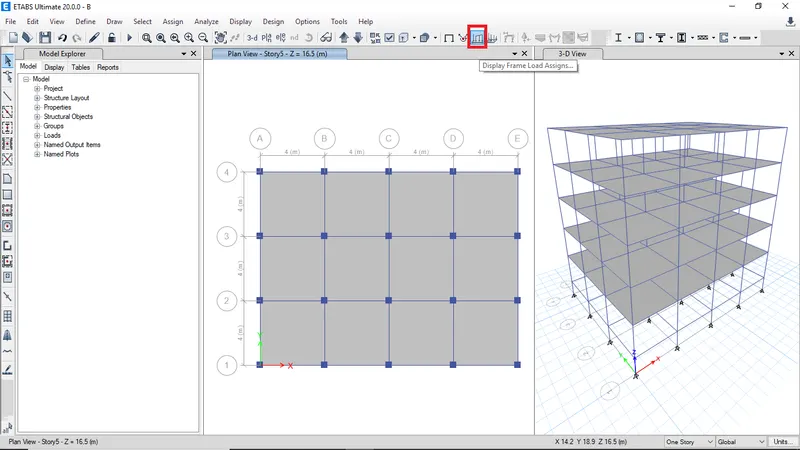
To check the assigned loads clik on display frame load assign
-
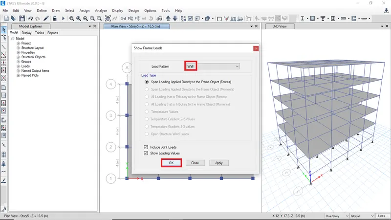
select wall load then click ok
-
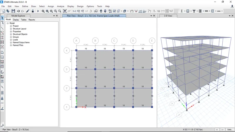
The loads will be visible and confirmed as all the loads were assigned
-
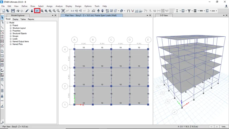
Click run analysis
-
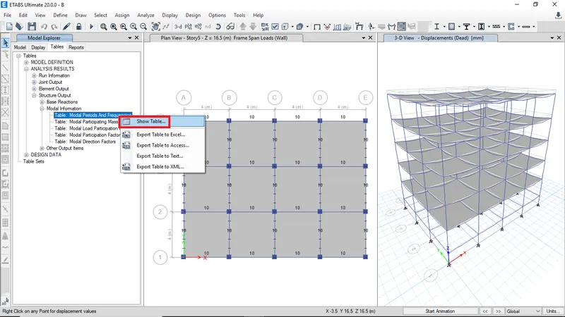
Right click and show table to view the modal periods
-
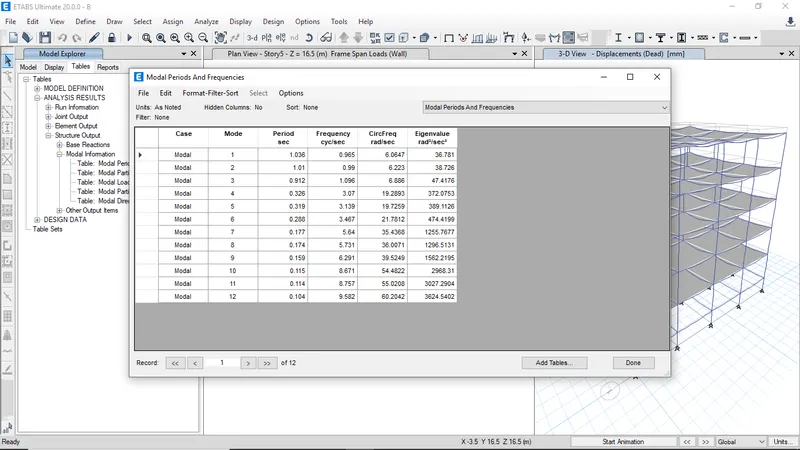
The modal periods and frequencies for building B
BUILDING C -
The Building C has same number of stories and parameters as Building B but the column dimensions of building C were different
-
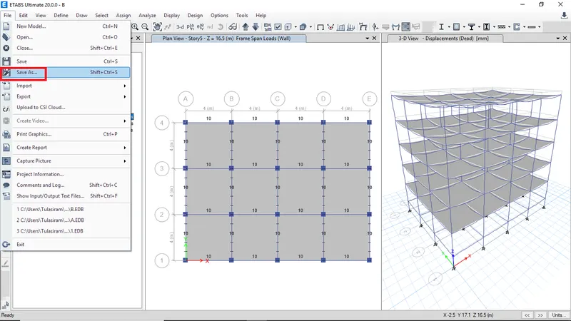
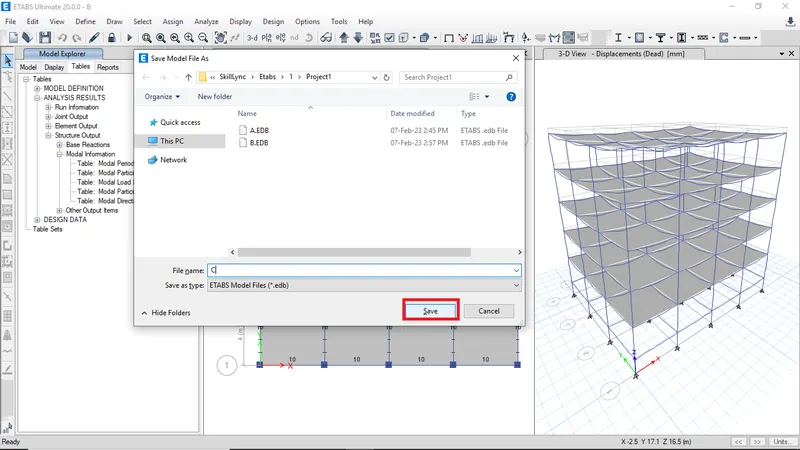
Click on save as to continue on same model
-
Enter the Building name as C then click save
-
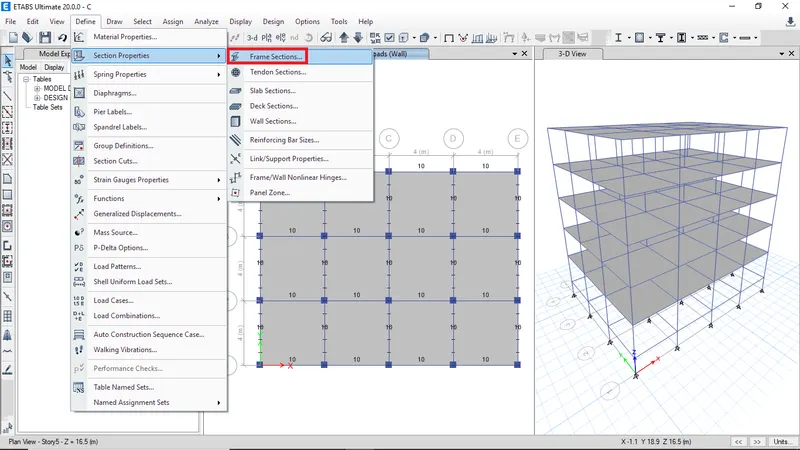
To edit the frame sections goto section properties then select frame sections
-
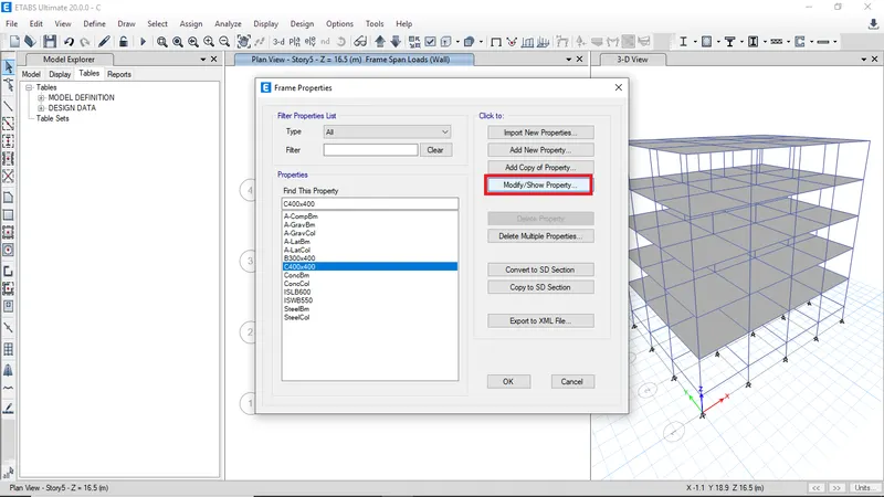
Select column C400x400 then click modify
-
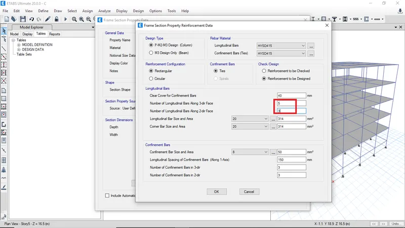
Modify the number of bars along each face
-
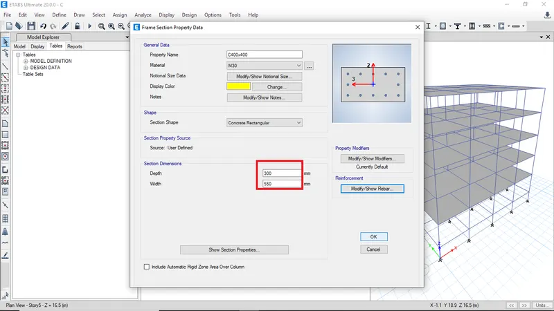
Change the depth and width of the column and also change property name
-
The modified property will be reflected in the model
-
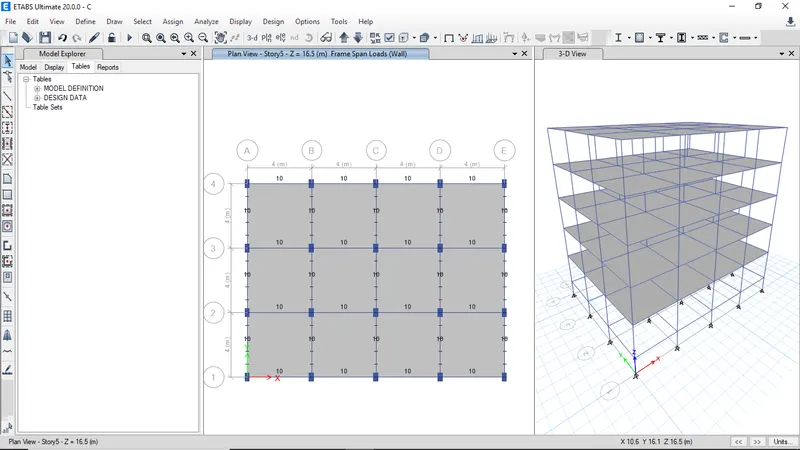
But the orientation of columns need change
-
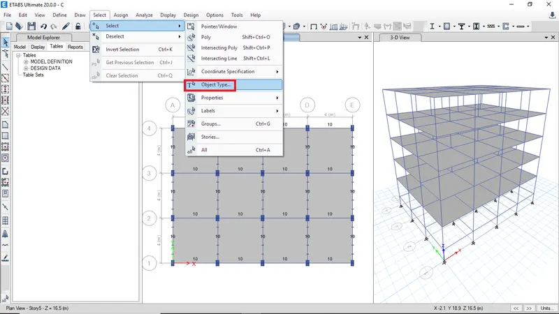
Select all the cloumns using object type
-
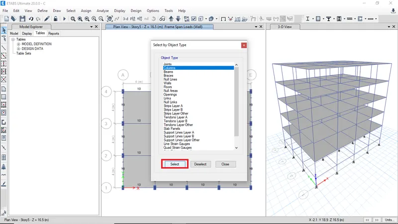
Click columns and click select
-
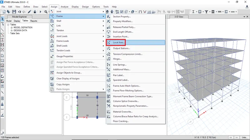
Then goto frame then click on loacal axes
-
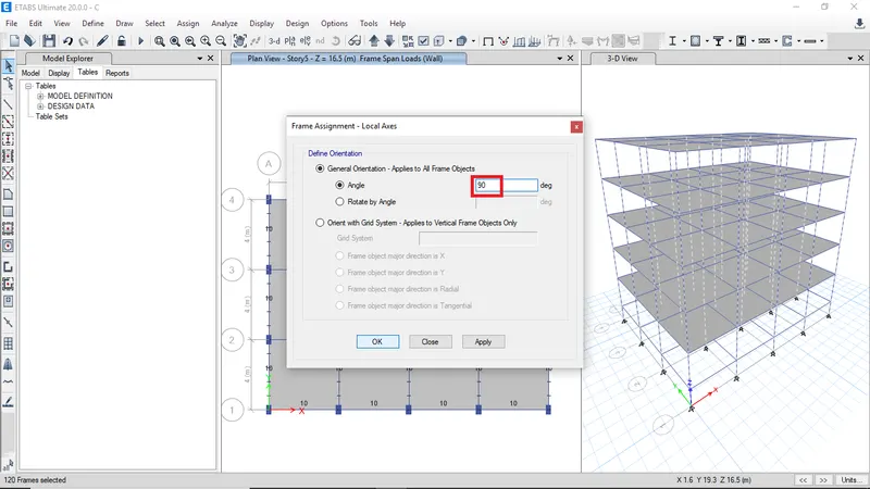
Then provide the angle as 90 and click ok
-
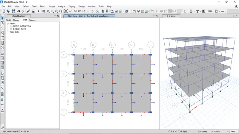
The changed orientation of the columns will be reflected in the model
-
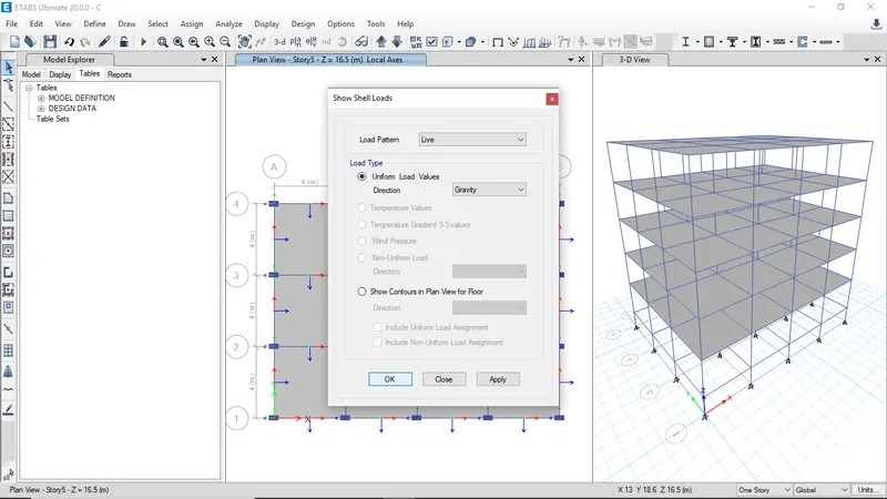
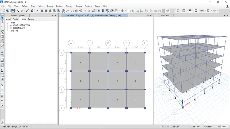
Click on didplay shell loads to check the assigned loads to slab
-
The assigned shell loads will be visible and verify the loads assigned to all slabs
-
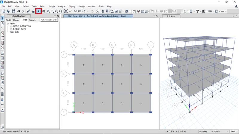
Click run analysis
-
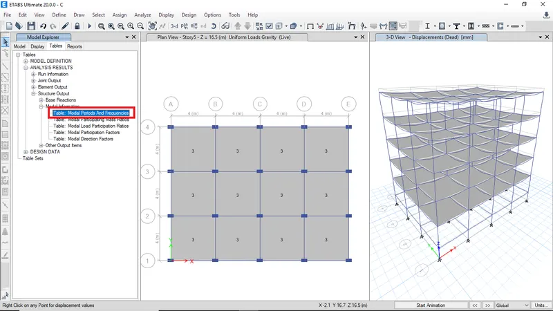
Select the Model periods from analysis result table then right click on open table to view results
-
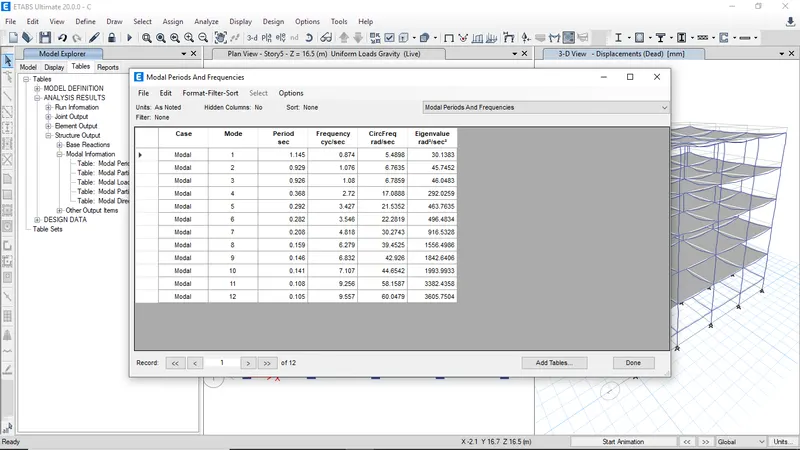
The modal periods and frequencies for Building C
BUILDING D -
The Building D has same parameters as Building C but orientation of the column is different
-
Click on save as to continue on same model
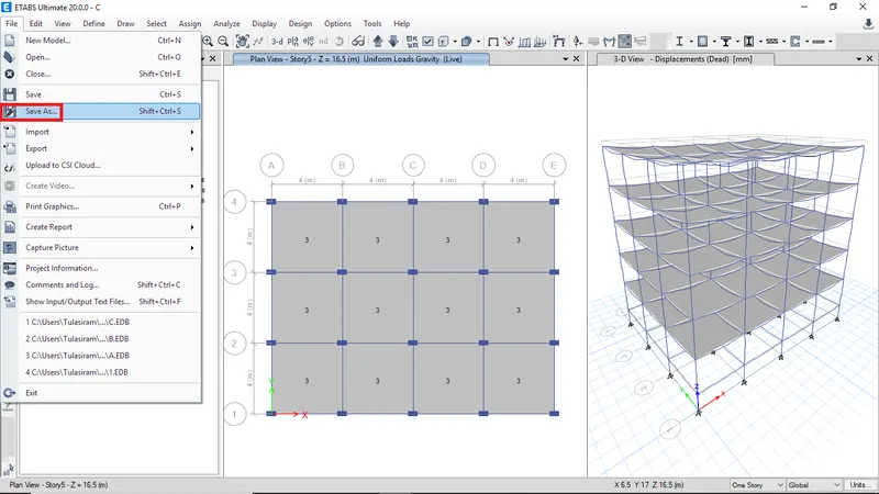
-
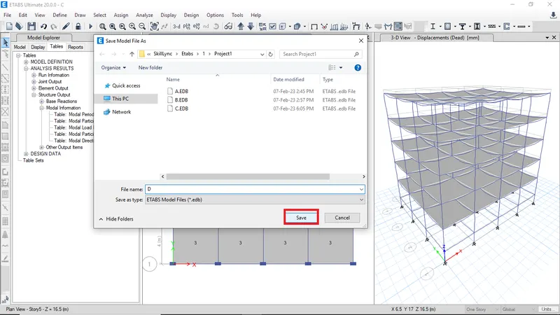
Enter Building name as D then click save
-
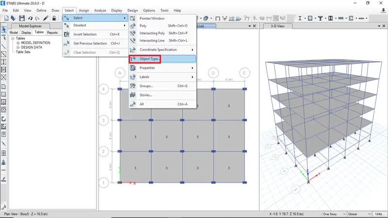
To change the orientation of the column select all the columns from object type
-
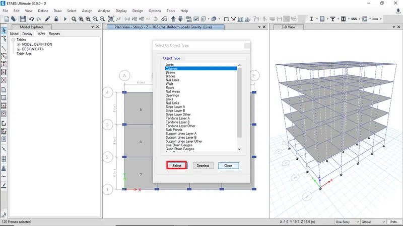
Click on columns then click on select
-
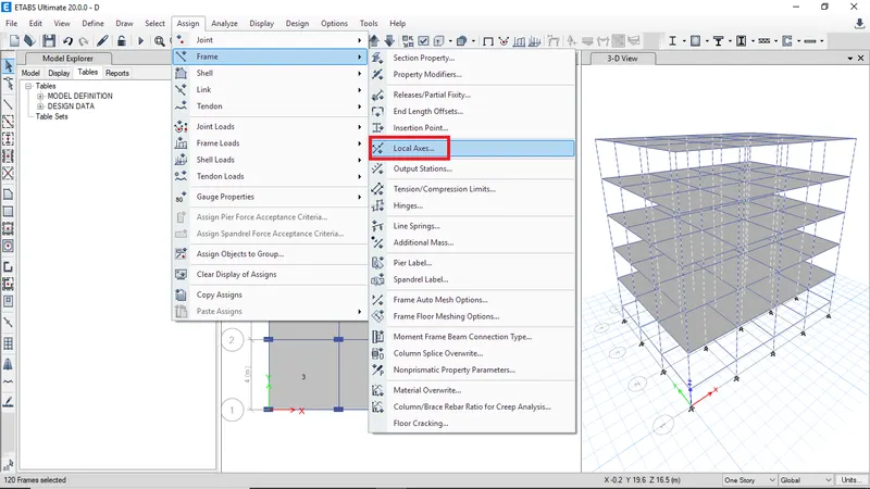
Go to frame thn click local axes
-
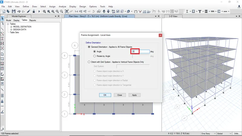
Enter the orientation angle as 0 then click ok
-
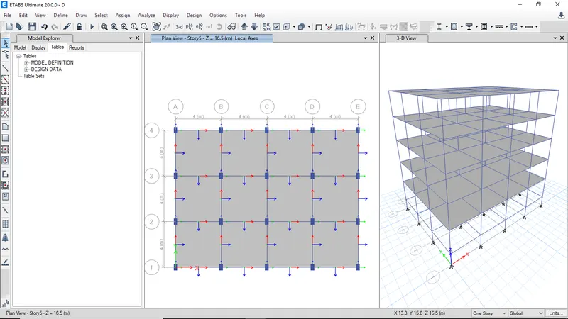
The orientation of the column is reflected in model click save to save
-
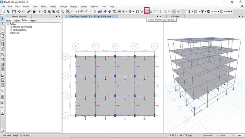
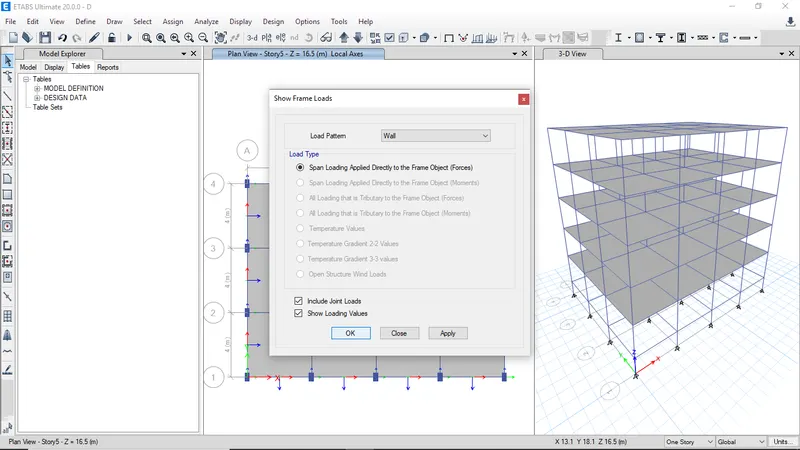
Click on Display frame loads to check the assigned loads
-
Select wall load then click ok
-
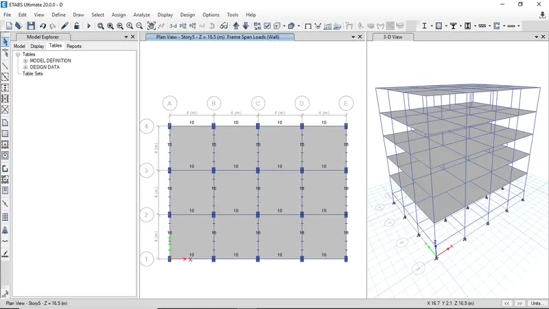
The assigned wall loads on bemas will be visible
-
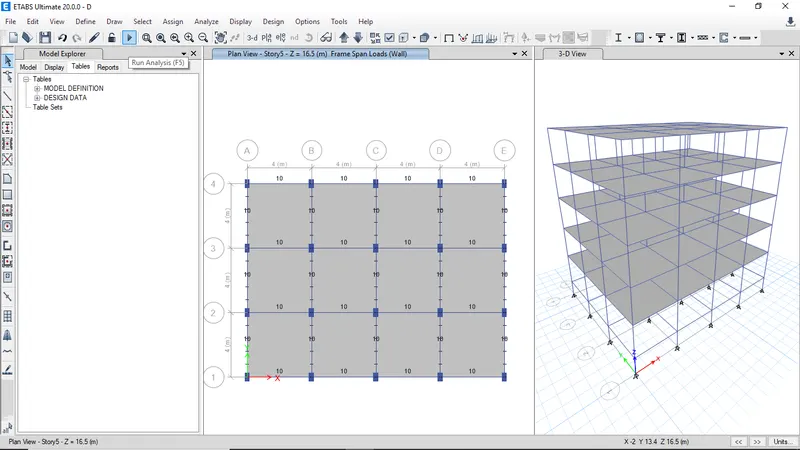
Click on run analysis
-
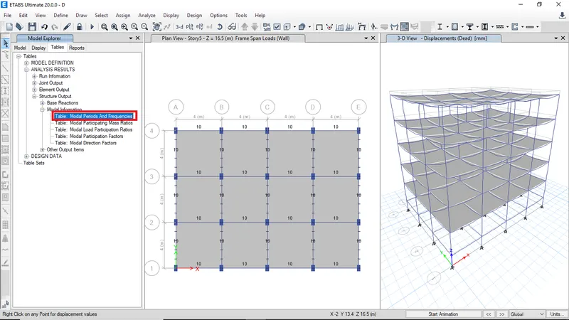
Select the Model periods from analysis result table then right click on open table to view results
-
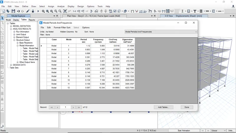
The modal periods and frequencies for Building D
BUILDING E -
The Building E has 10 stories with C400x400 on upper 5 stories and C600x600 on bottom 5 stories
-
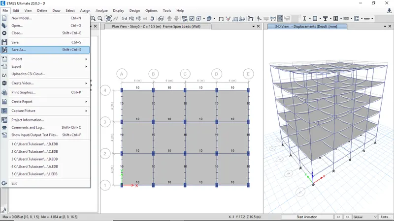
Click on save as to continue on same model
-
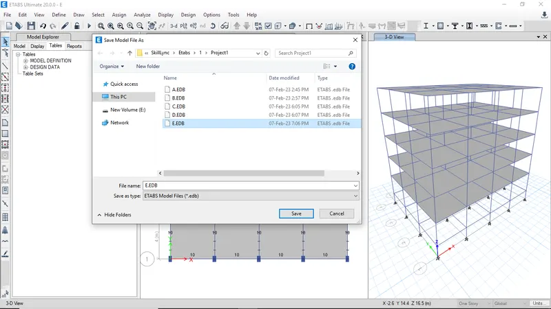
Enter the name Building E and click save
-
The old model has 5 stories so need to ass extra 5 stories
-
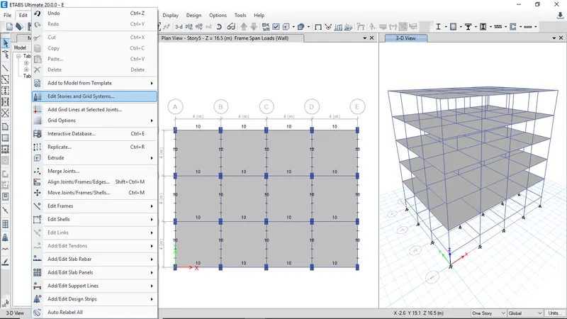
Click on Edit then select Edit stories and Grid sytems
-
Click on modify to modify story data
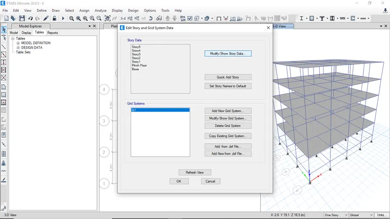
-
Right click and select add story
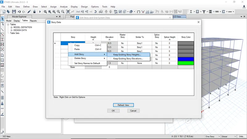
-
Enter the number of added stories as 5
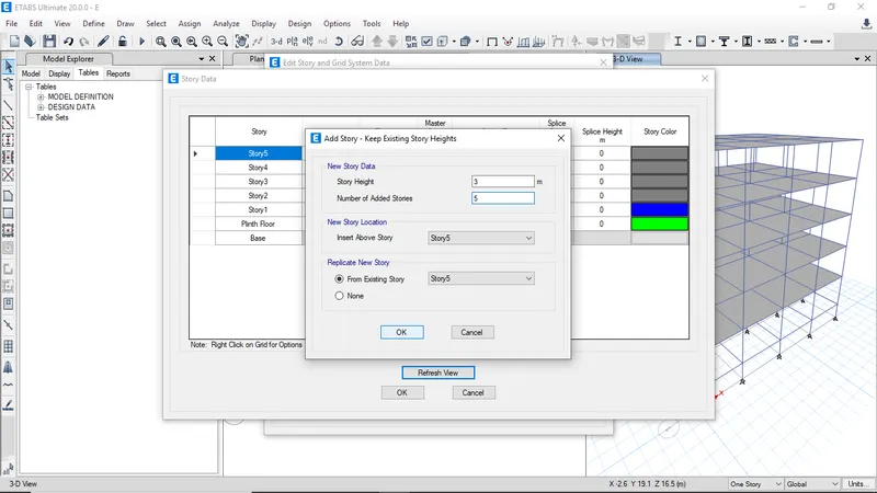
-
After creating stories chose similar storey
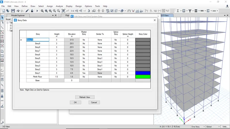
-
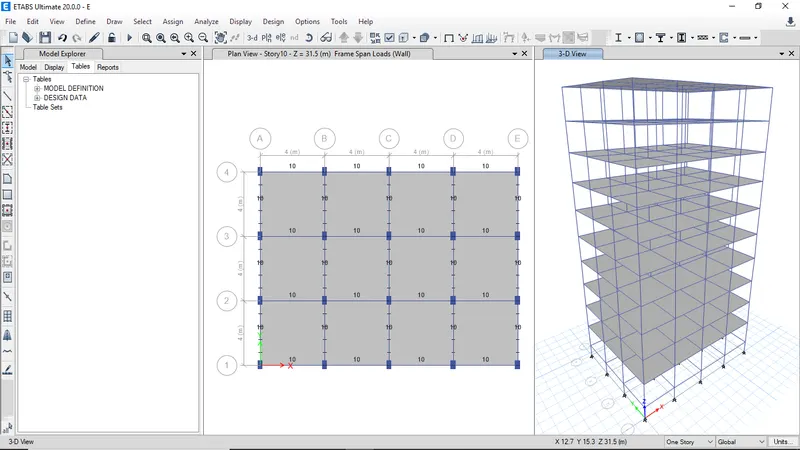
Verify the loads assigned
-
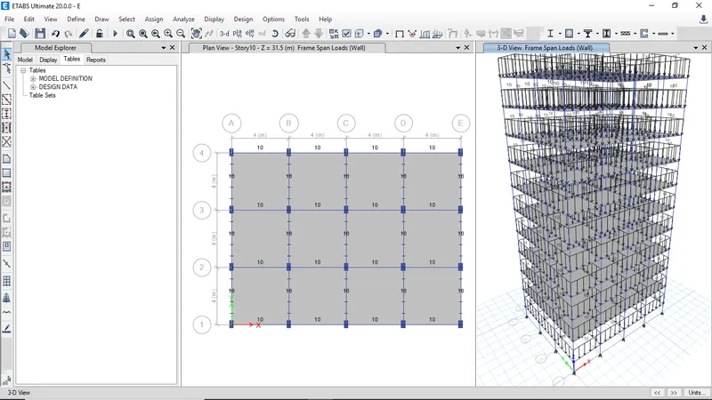
Check for all the assigned loads
-
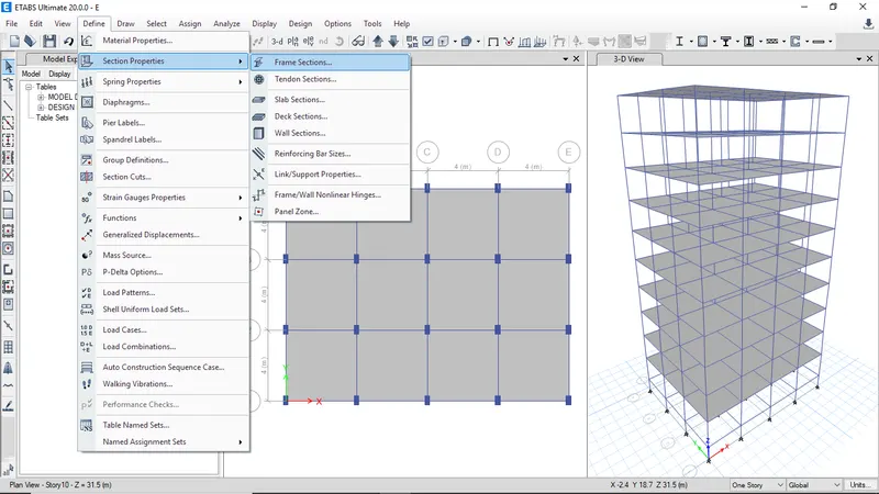
To change the frame properties go to section properties then select frame sections
-
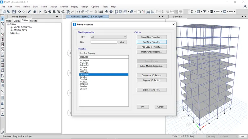
To add column property click on add new property
-
Select the rectangular section
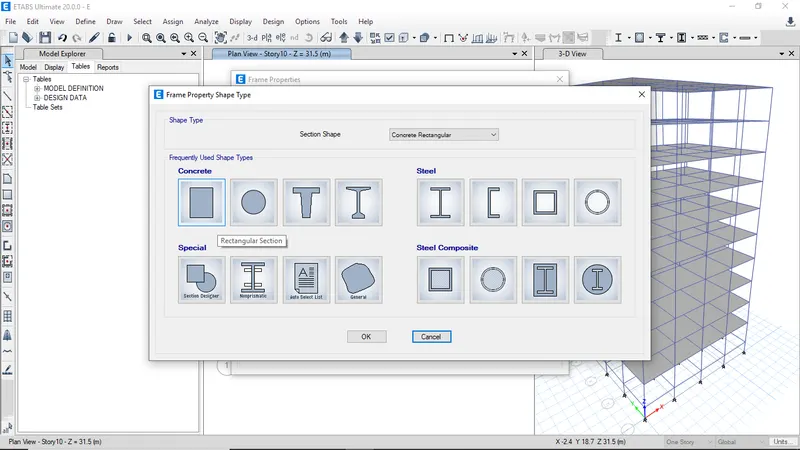
-
Selec the reinforcement data and modify it
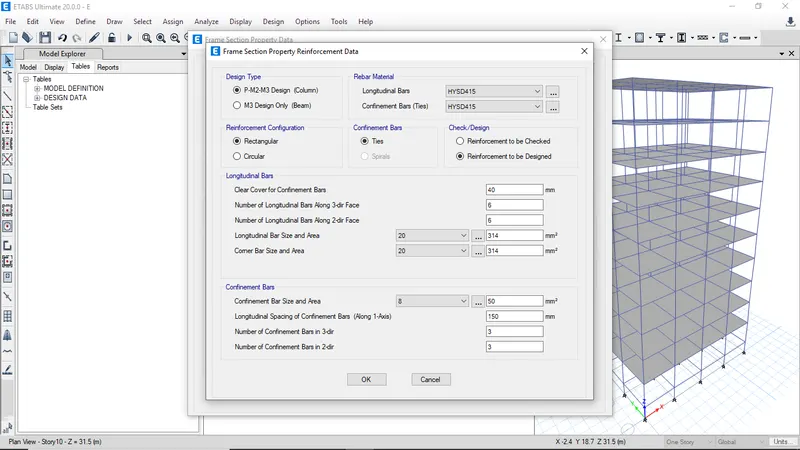
-
Enter then depth and width of clumn then click ok
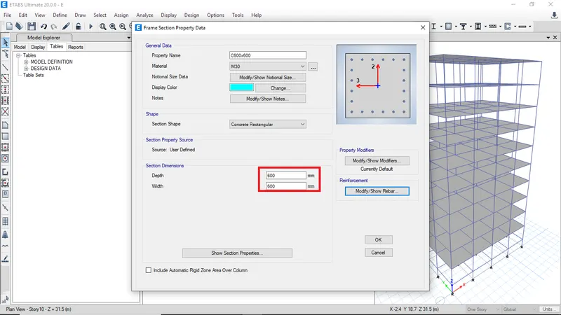
-
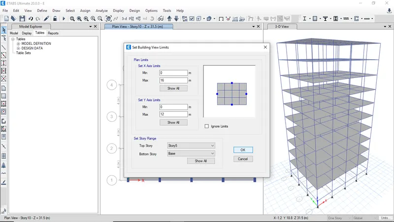
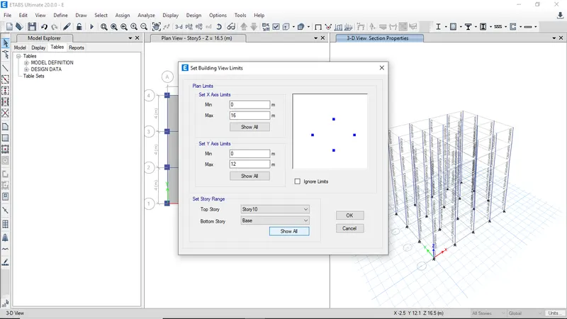
To assign different column property for botton stories need to set view limits
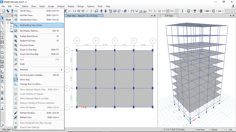
-
Goto view and select set view building limits
-
Select the bottom and top story then click ok
-
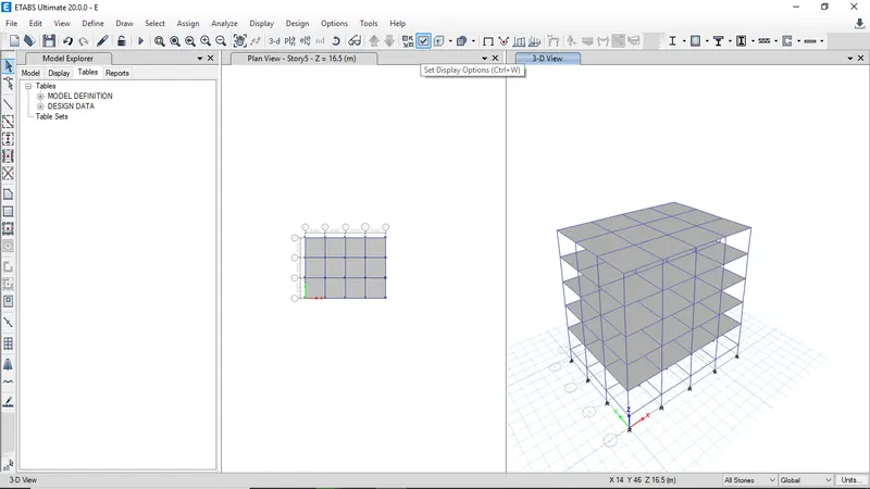
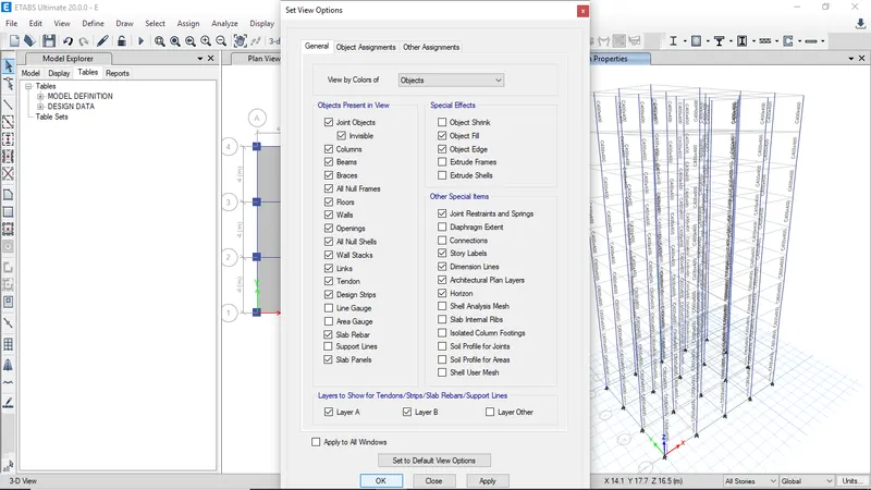
To select only columns need to hide slabs and beams
-
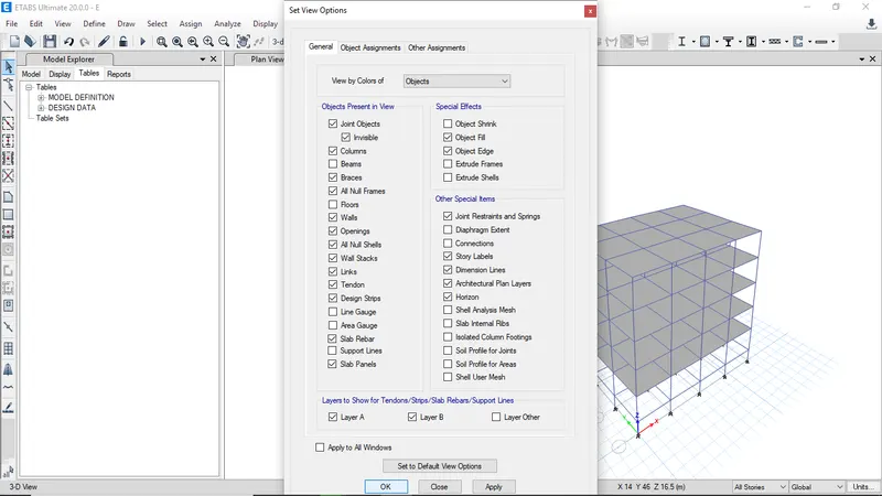
Click on set display options
-
Uncheck beams and floors then click ok
-
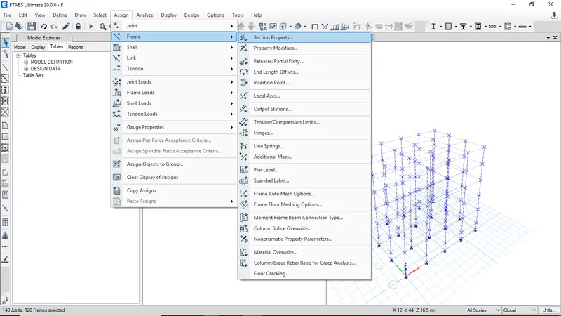
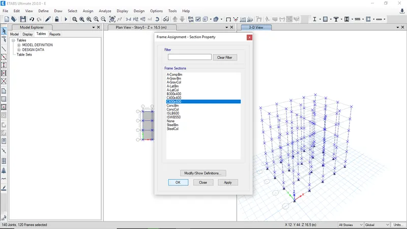
Select all the columns and click on frame and select srction property to assign frame property
-
Select column C600x600 then click ok to assign them for bottom 5 stories
-
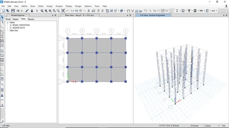
All the assigned properties can be checked
-
To reset the building view limits click on show all then click ok
-
Now all the columns of all stories will be visible
-
To show all the hidden beams and floors, click on set view options
-
Then select beams and floors and click ok
-
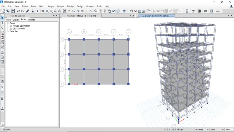
Now all the elements will be visible
-
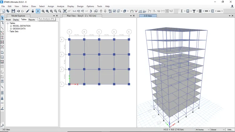
Click on run analysis
-
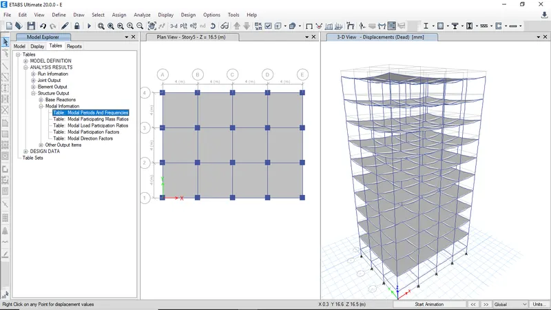
Select the Model periods from analysis result table then right click on open table to view results
-
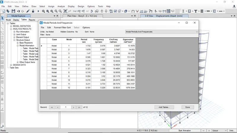
The modal periods and frequencies for Building E
BUILDING F -
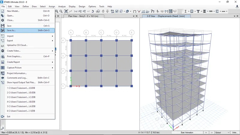
The Building F has columns of C600x600 in all stories other than that Building F is silimar to Building E
-
Click on save as to continue on same model
-
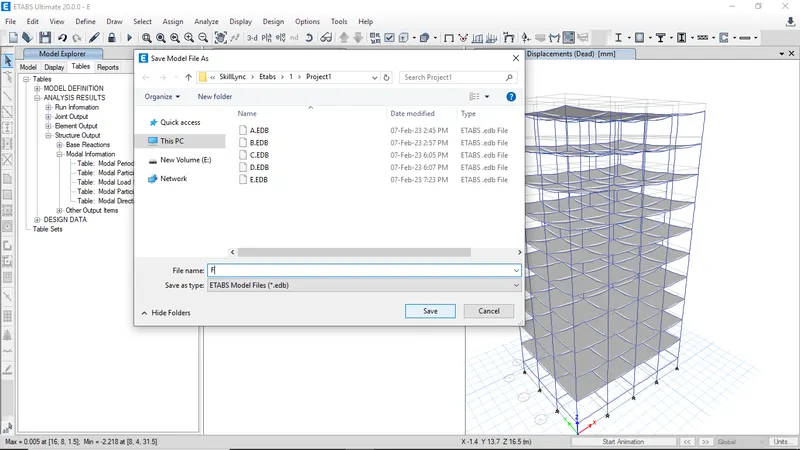
Enter model name as F and click save
-
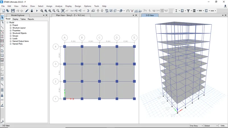
The model F has same stories as model E
-
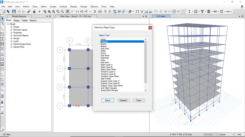
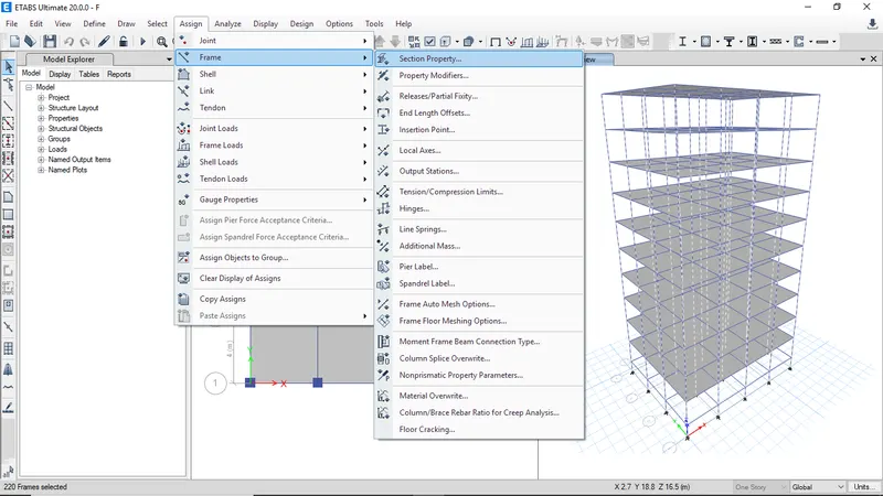
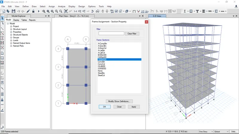
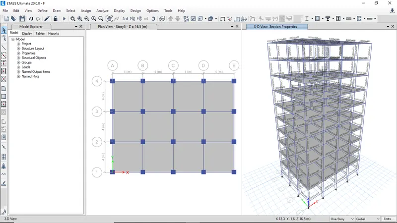
Need to assign column property C600x600 to all columns of Building F
-
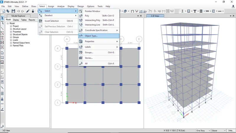
Select all columns from object type
-
Click on cloumns and click select
-
Goto assign frame than click on section property
-
Click on C600x600 then click ok to assign
-
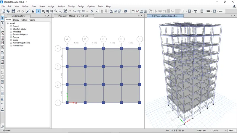
All the assigned properties are visible
-
Click run analysis
-
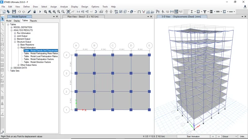
Select the Model periods from analysis result table then right click on open table to view results
-
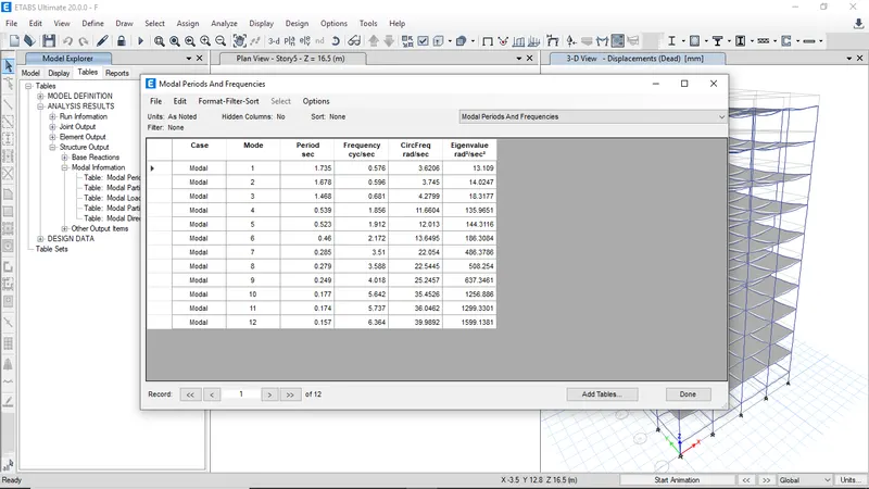
The modal periods and frequencies for Building F
BUILDING G -
The Building G has 25 stories with column size of 400x400 at upper 5 stories, 600x600 at middle 10 stories and 800x800 at bottom 10 stories
-
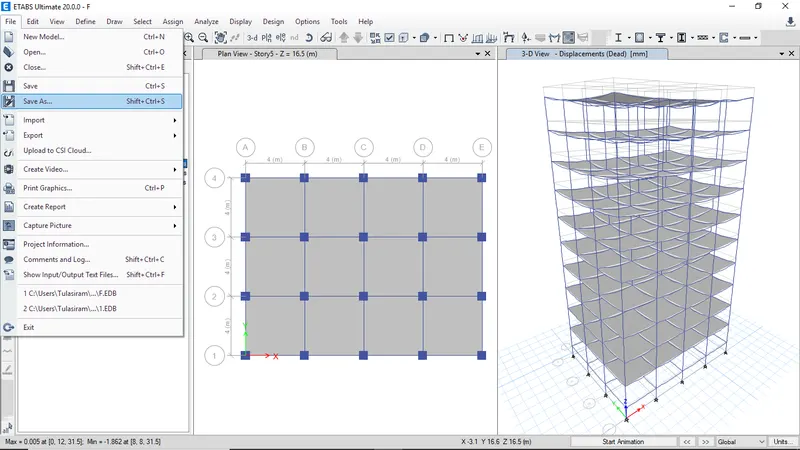
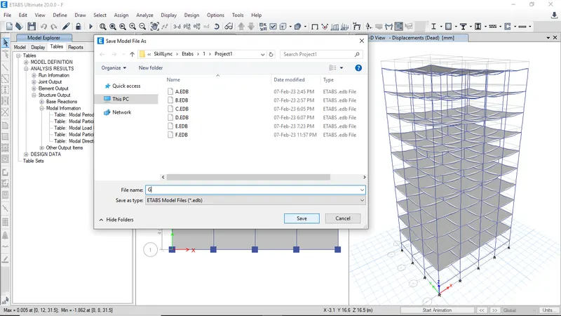
Click on save as to continue on same model
-
Enter Building name as G and click save
-
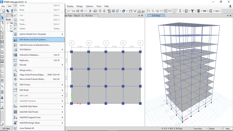
Goto edit and click on Edit stories and grid systems to add more stories
-
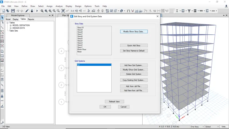
Click on modify to edit story data
-
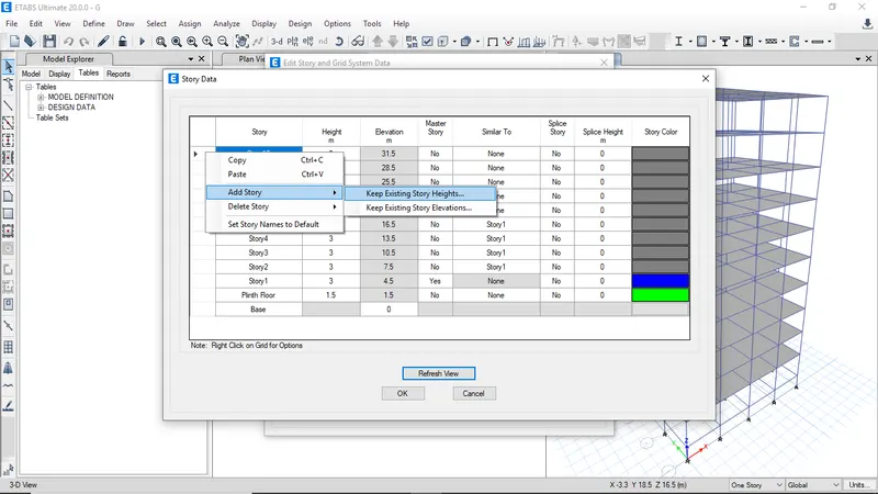
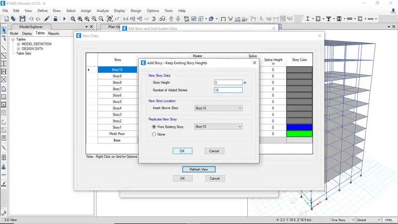
Rigth click and add story to add extra 15 stories
-
Enter the number of added stories as 15 yhen click ok
-
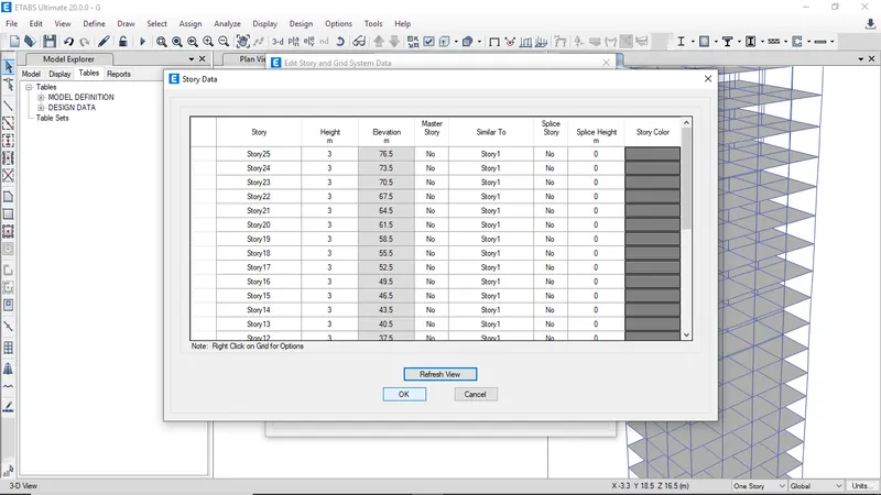
After adding all the stories assign similar story
-
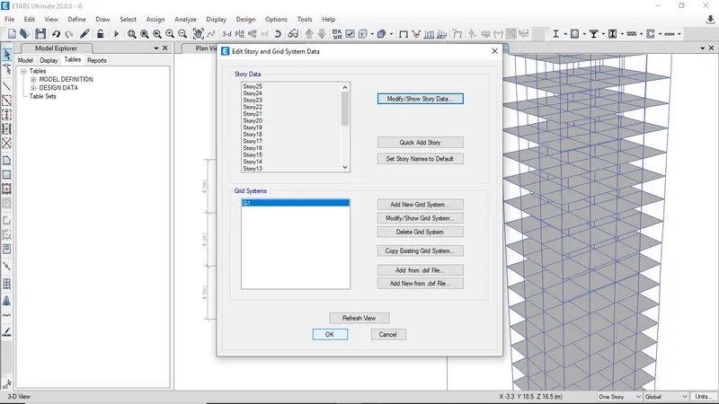
Then click ok to save story data
-
The added stories will be reflect in model
-
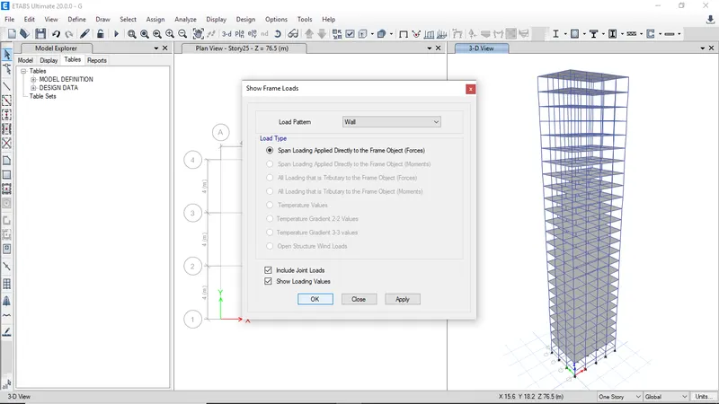
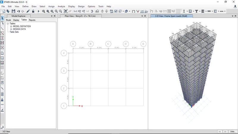
Verify all the assigned loads
-
The assigned loads will be visible
-
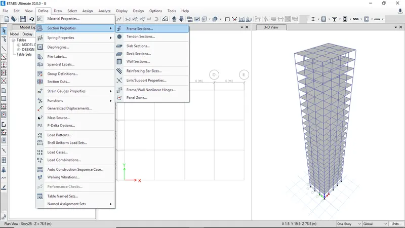
To define column property goto define and click on section properties and select frame sections
-
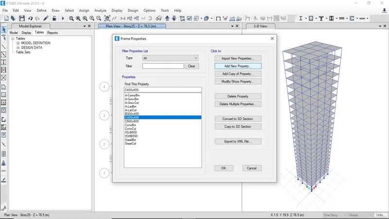
Click on add new property
-
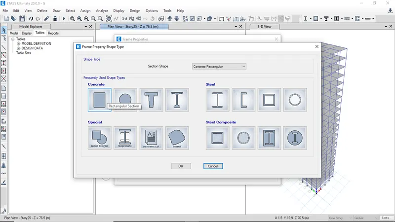
Select rectangular section
-
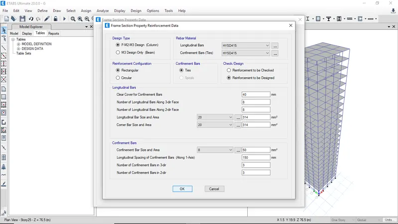
Modify reinforcement data and enter the number of bars along each face
-
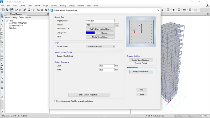
Enter the width and depth of column then click ok
-
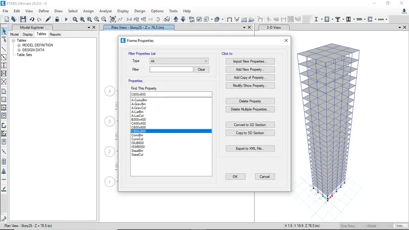
After defining all the column properties click ok
-
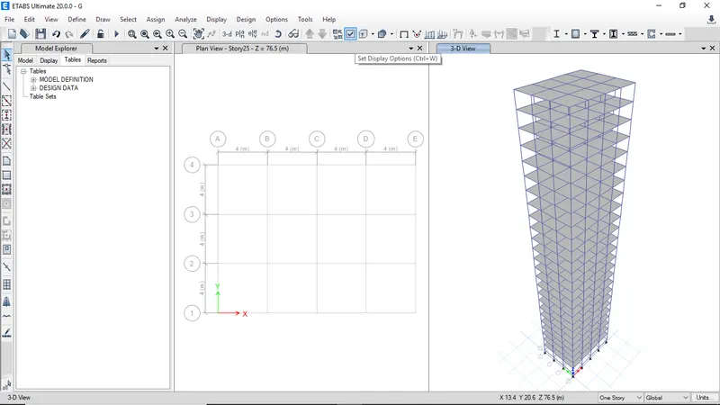
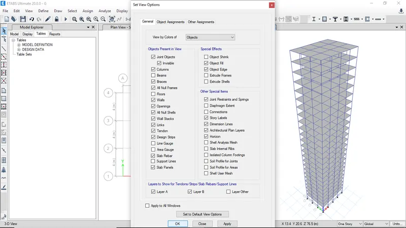
Click on set display options to hide floors and beams
-
Uncheck beams and floors then click ok
-
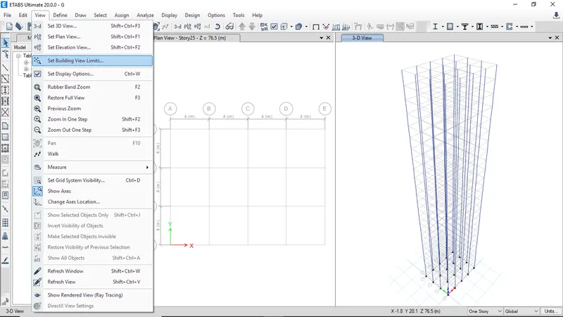
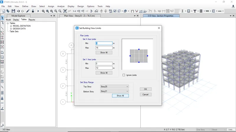
To set the view limits got to view then select set building view limits
-
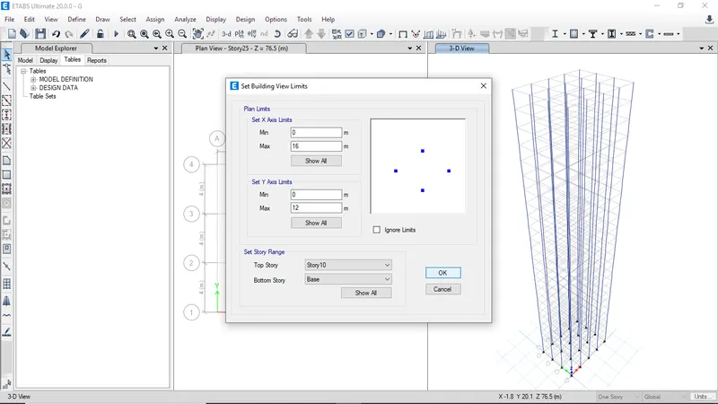
First set bottom story as base and top story as story 10 then click ok
-
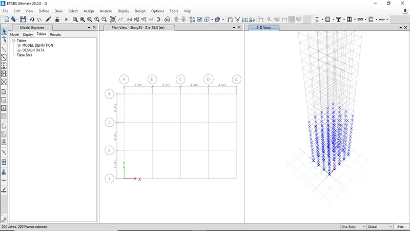
Now select all the columns
-
Goto assign then frame and select section property
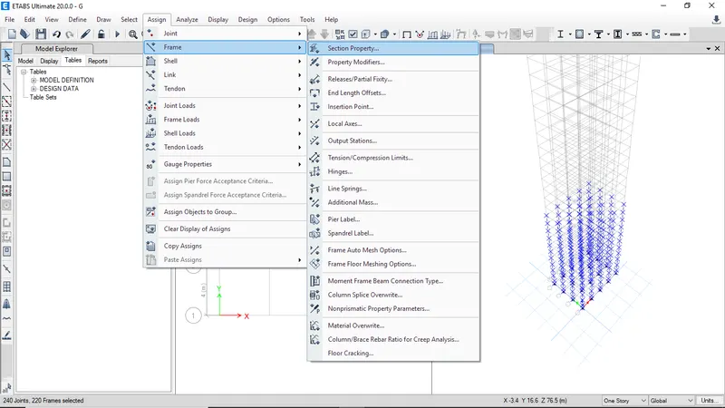
-
Select C800x800 column to assign the property to selected columns
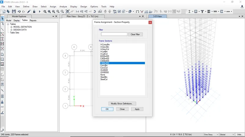
-
The peoperty is assigned to selected to selected columns
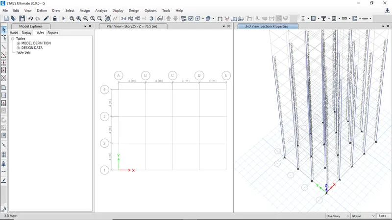
-
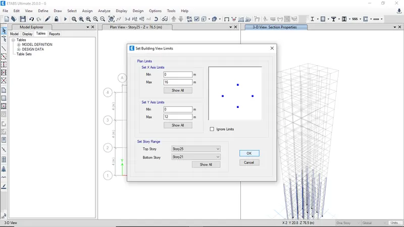
Then now change the view limits from view and select set building view limits
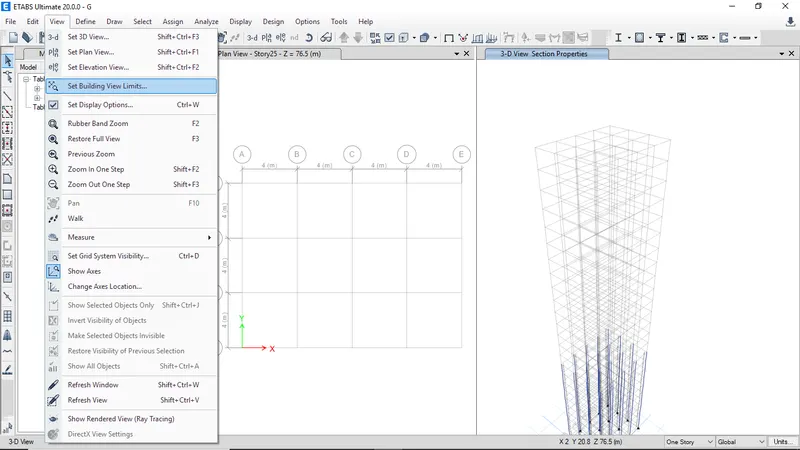
-
Now select bottom story as story 21 and top story as story 25 then click ok
-
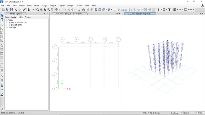
Select all the columns
-
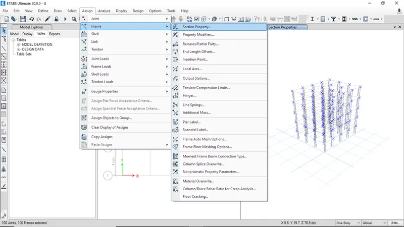
Click on section property from assign frame option
-
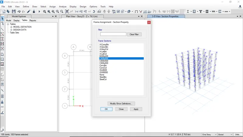
Now select C400x400 then click ok to assign
-
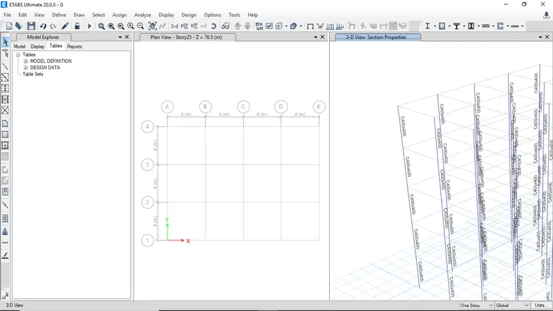
All the assigned property is visible
-
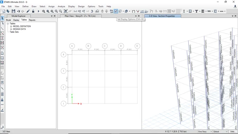
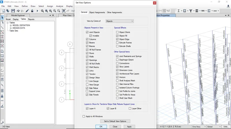
Click on set display options to get back beams and floors
-
Check beams and floors then click ok
-
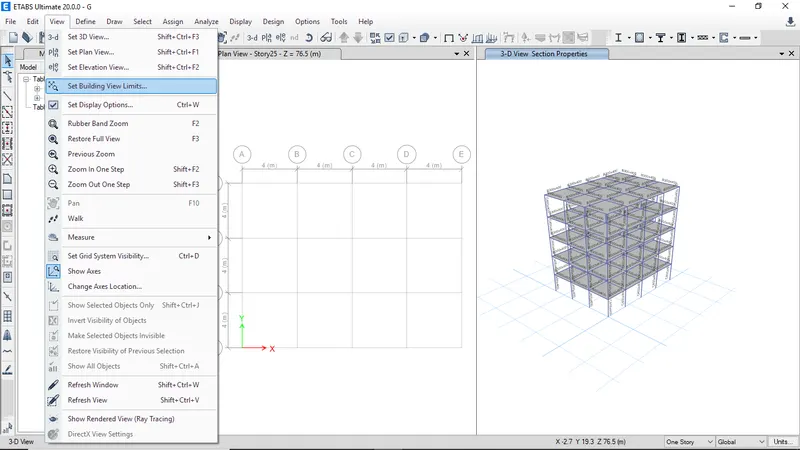
Now reset the view limits
-
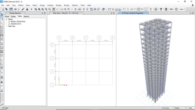
Click on show all to view all stories then click ok
-
Now all the elements were visible
-
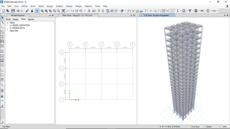
Click run analysis
-
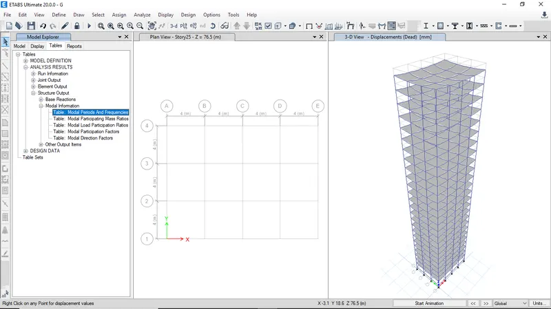
Select the Model periods from analysis result table then right click on open table to view results
-
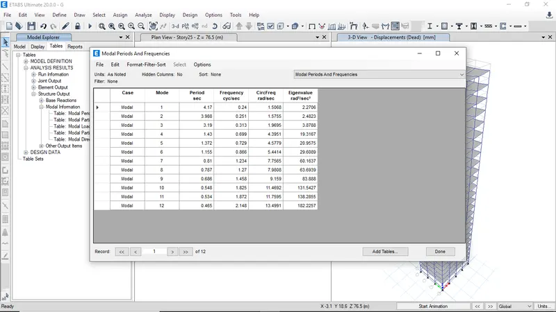
The modal periods and frequencies for Building G
BUILDING H -
The Building H has all the columns of dimension 800x800 other than that all the parameters are same as Building G
-
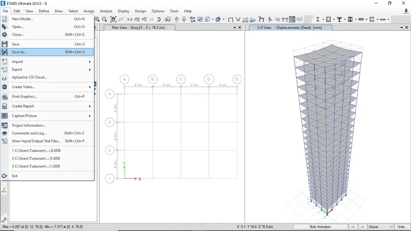
Click on save as to continue on same model
-
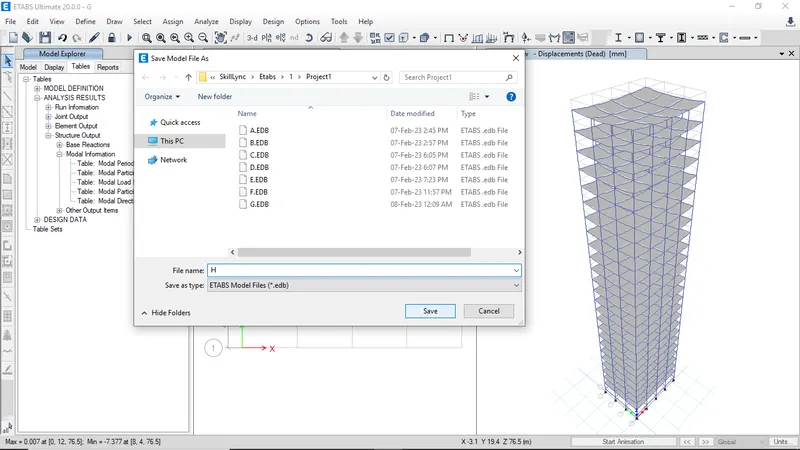
Enter building name as H then click save
-
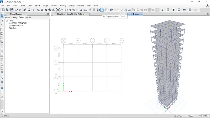
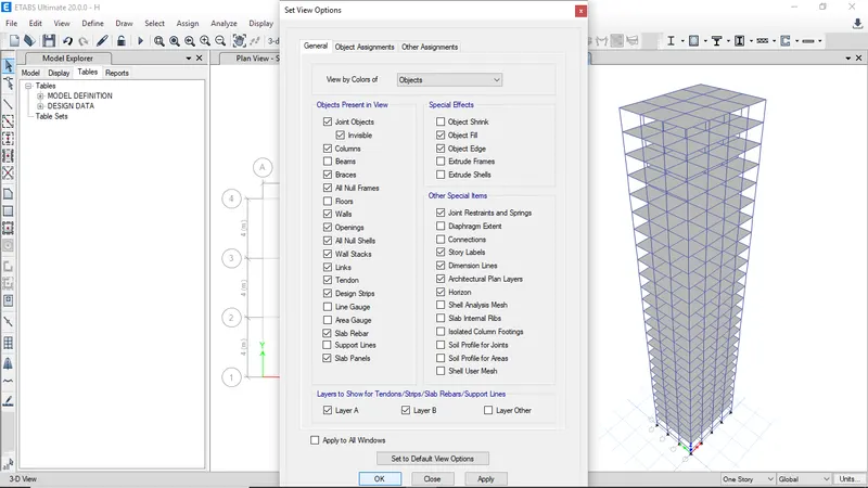
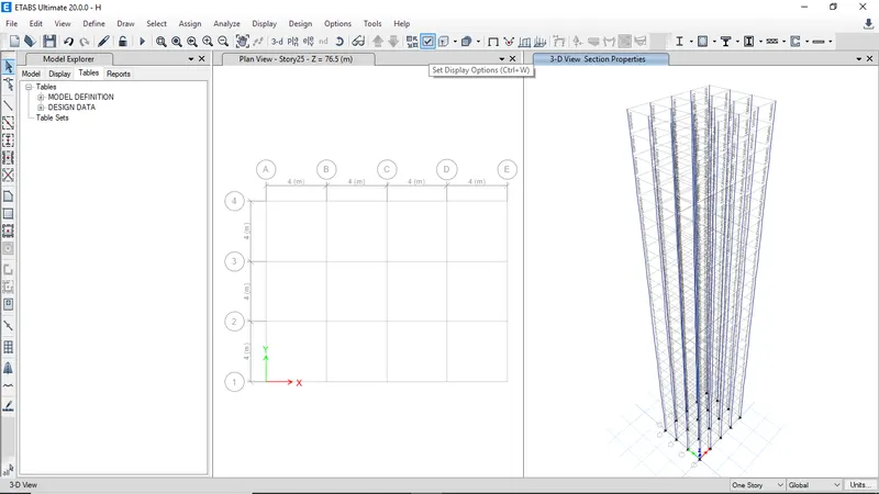
Click on set display options to hide beams and floors
-
Uncheck beams and floors then click ok
-
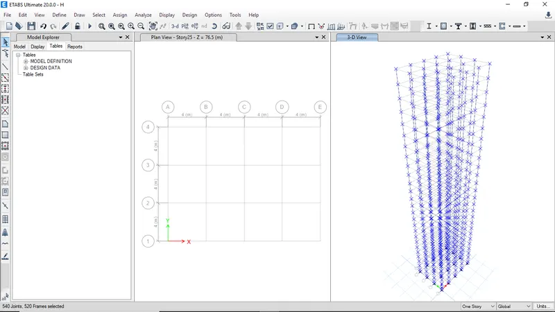
Select all the columns
-
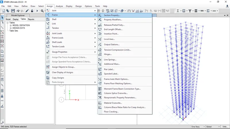
Goto assign and select frame then section property
-
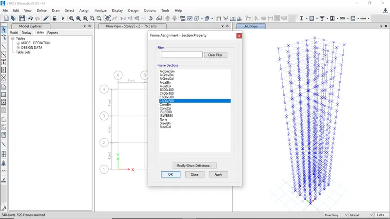
Select C800x800 then click ok to assign
-
All the assigned property will be visible
-
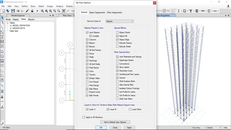
Then turn on beams and floors from the set view options
-
Check beams and floors then click ok
-
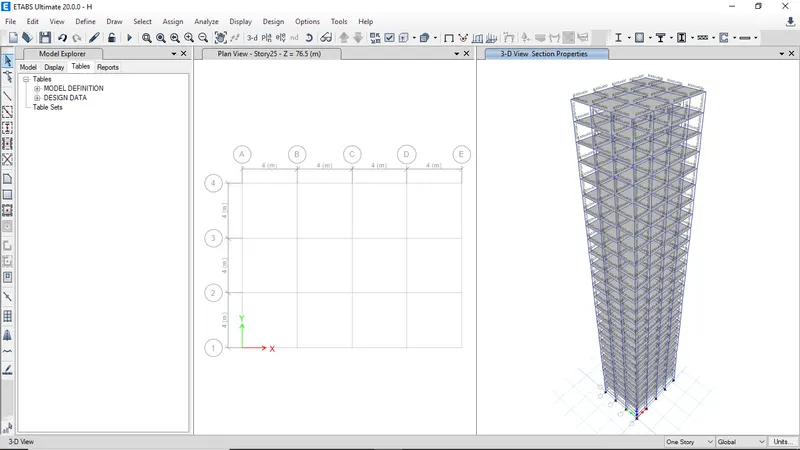
All the elements now visible
-
Click run analysis
-
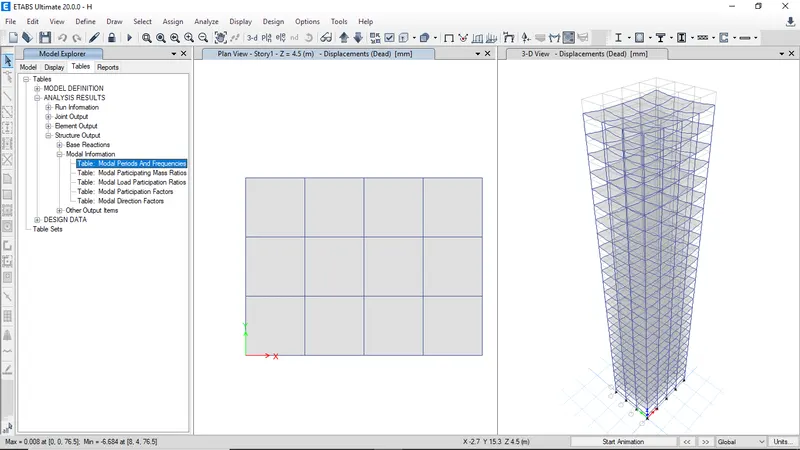
Select the Model periods from analysis result table then right click on open table to view results
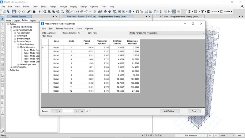
-
The modal periods and frequencies for Building H
BUILDING J - Building J is similar to building H but the imposed load is l10% larger than Buildinh H
-
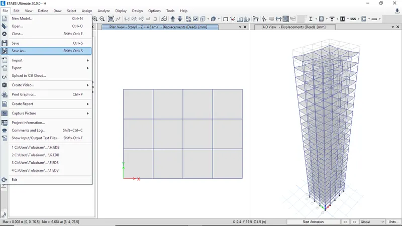
Click save as to save and continue same model
-
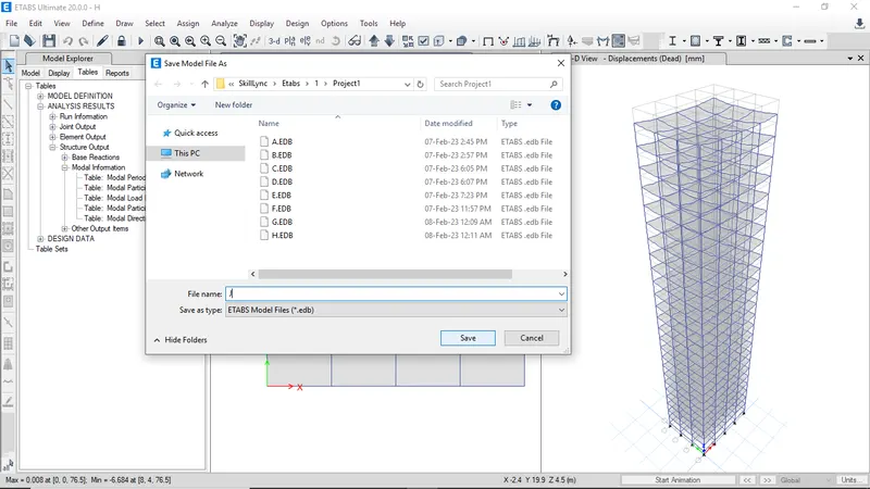
Enter the name of building as J and click save
-
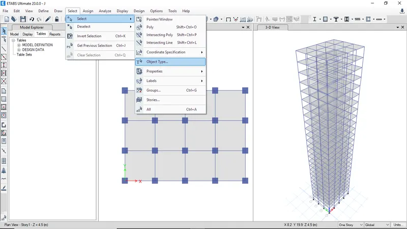
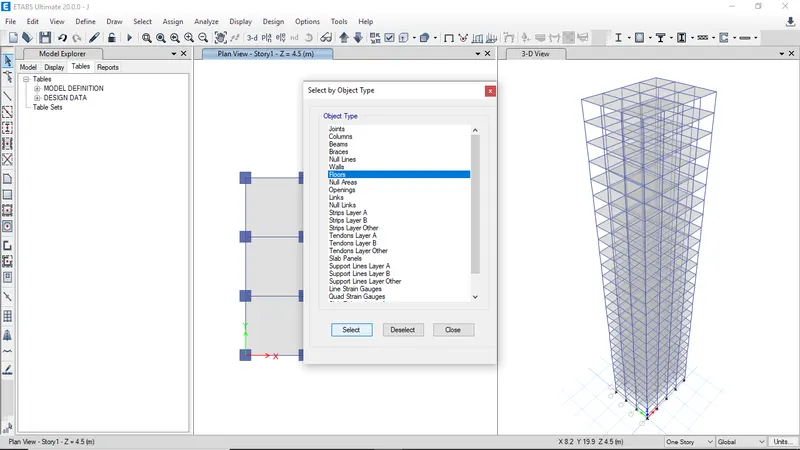
Now select the slabs using object type
-
Now click on floors and then click on select to select the floors
-
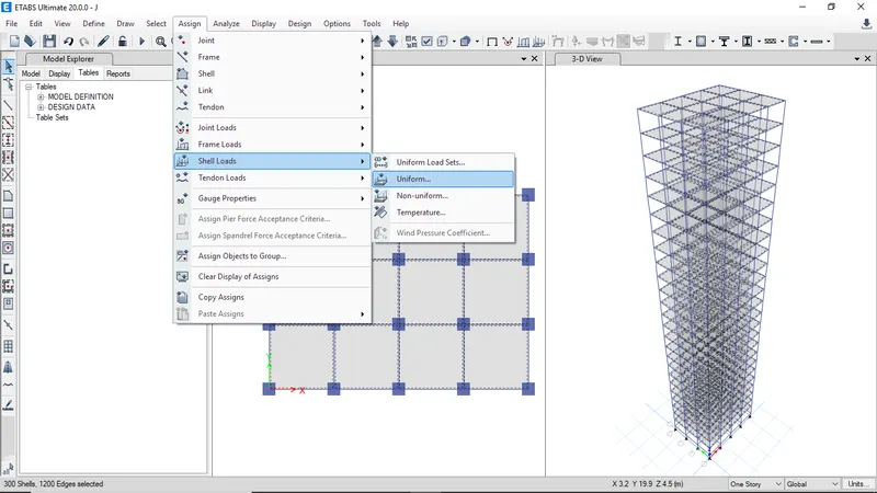
Then click on assign shell loads and select uniform load
-
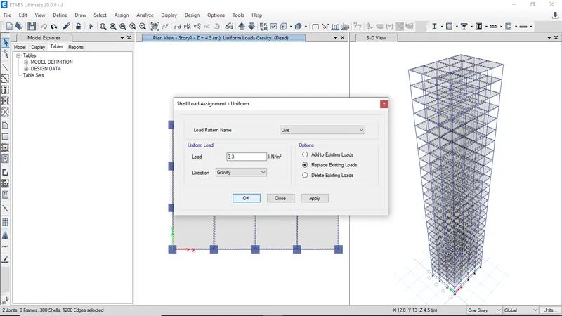
Now select Live load and enter load value as 3.3 kN/m2 and make sure to check replace existing load
-
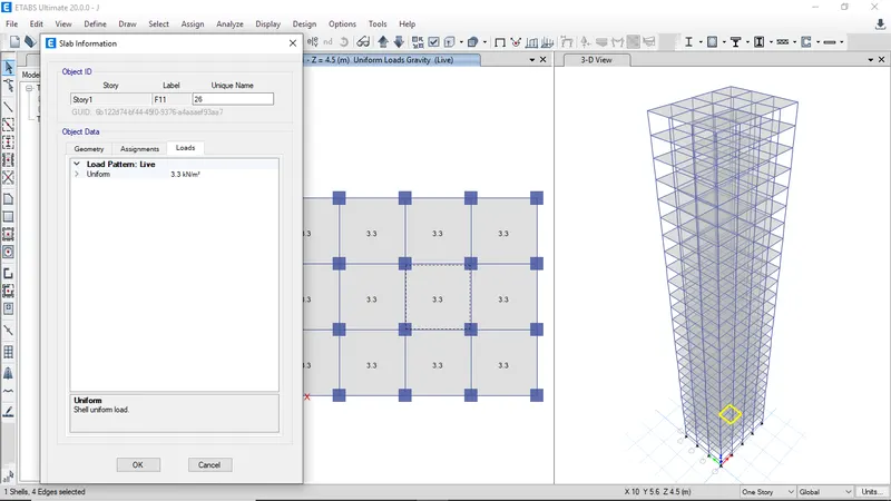
To confirm the assigned loads on slab right click on slab and view assigned loads
-
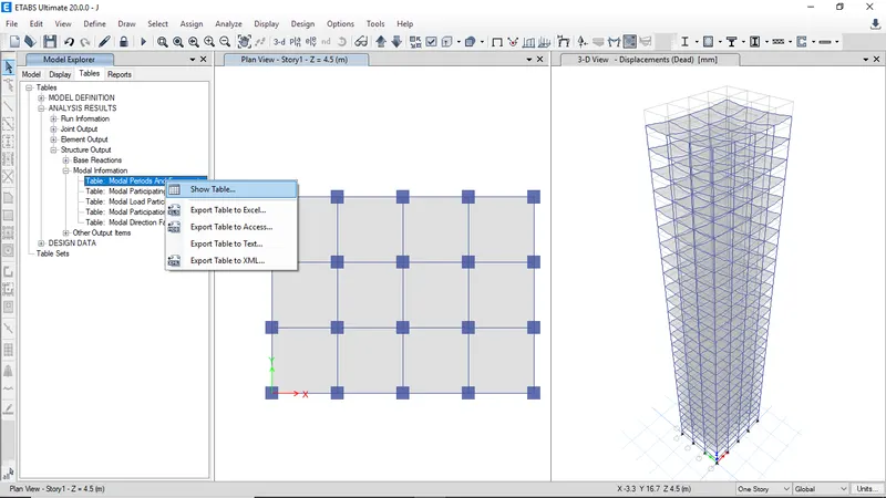
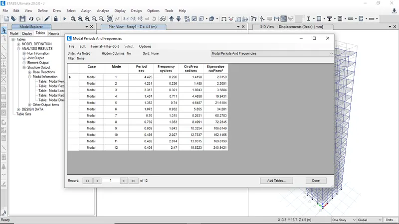
Now select Modal periods table from the structure output and right click to view table
-
The modal periods and frequencies table for Building J
BUILDING K -
Building K is similar to Building H but imposed load is 20% larger than Building H
-
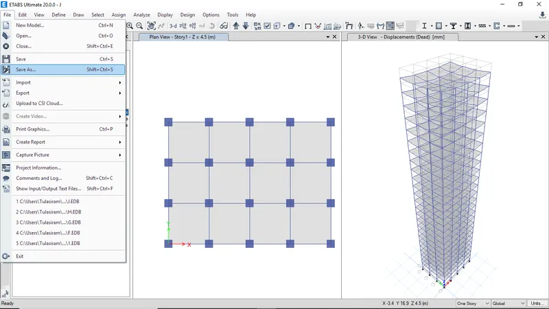
Click on save as to save and continue same model
-
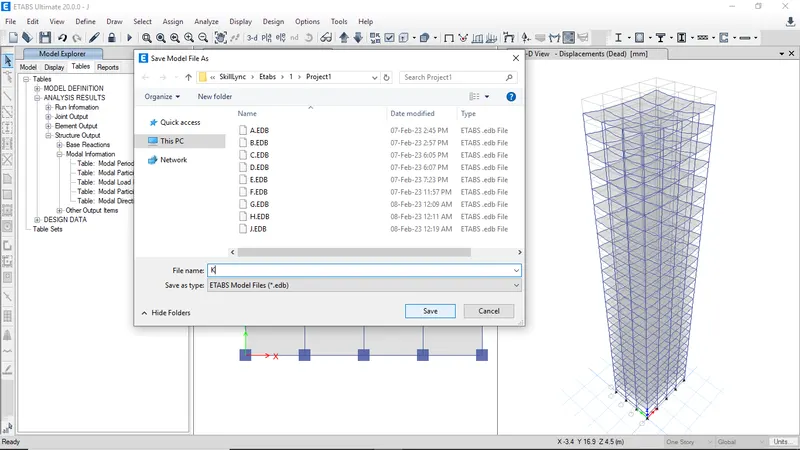
Now enter building name as K and click Save
-
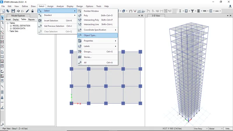
Now select the slabs from object type
-
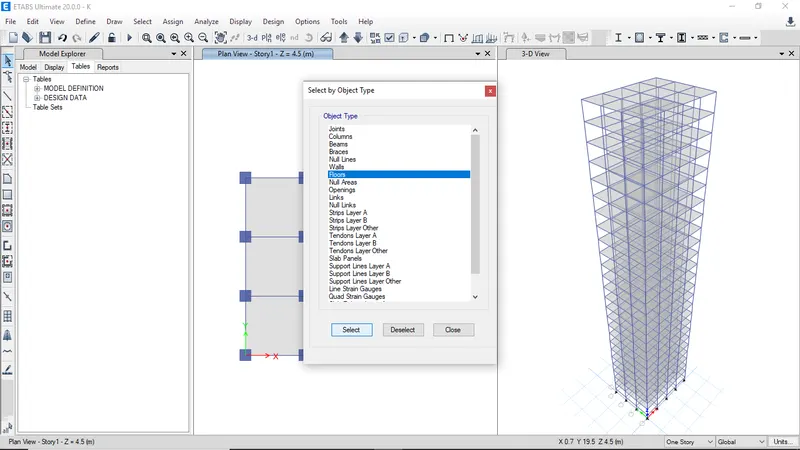
Sleect floors and click select
-
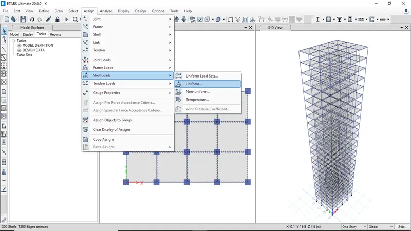
Now assign shell loads then select uniform load
-
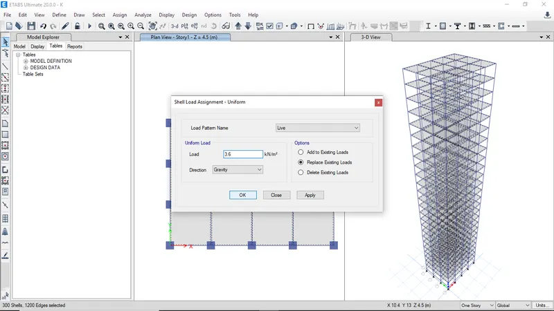
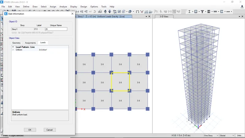
Select live load and enter the load value as 3.6 kN/m2 and make sure to select replace existing loads
-
To verify assigned loads on slab right click and view the assigned loads
-
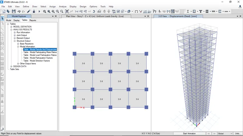
Select modal periods table from the Structure output and right click to view table
-
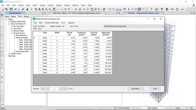
The modal periods and Frequencies for Building K
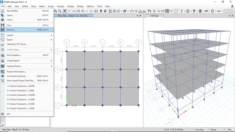
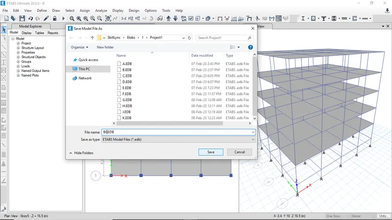
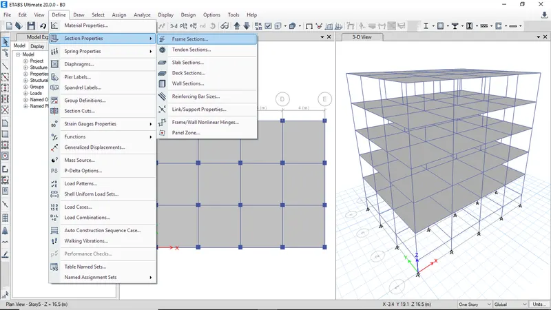
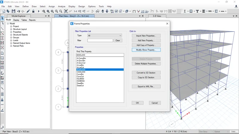
BUILDING B with 10% flexural stiffness (MOMENT OF INERTIA 10%) -
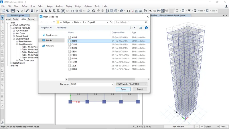
Open ETABS file of Building B
-
click on Save as to modify flexural properties
-
Enter the name of Building as B0 and click save
-
Now Goto define section properties and click on frame sections
-
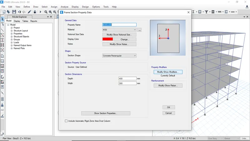
Now select beam B300x400 and click on modify
-
Now click on Property modifier
-
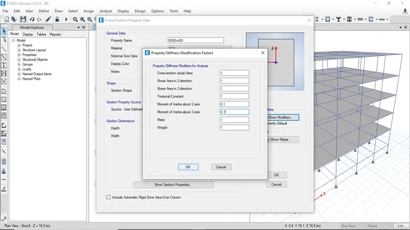
Change the moment of inertial about axis 2 and 3 to 10% i.e enter 0.1
-
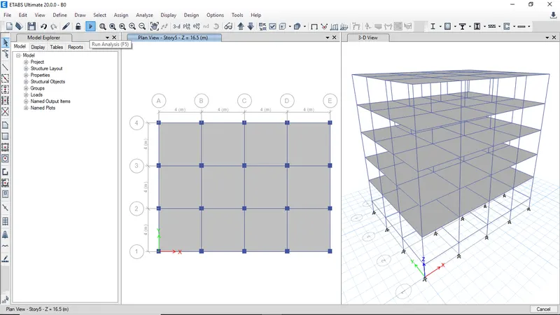
Then click Run analysis
-
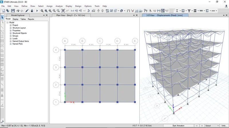
After completing analysis the deformed shape will be visible
-
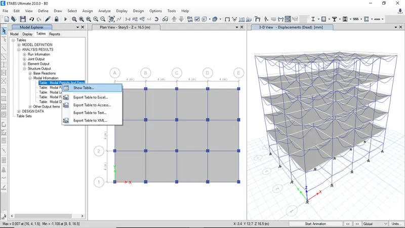
Then click on Modal periods table from structure output and right click show table to view table
-
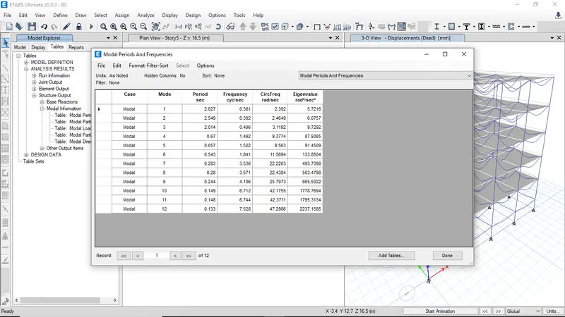
The Modal periods and frequencies for Building B with 10% flexural stiffness
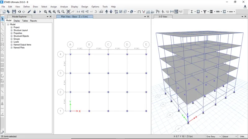
BUILDING B with base of the column is fixed -
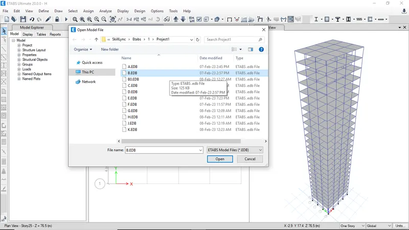
Open Etabs model of Building B
-
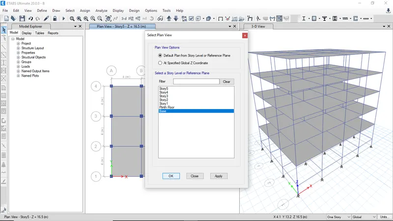
Switch to base floor plan view
-
Now select all the joints
-
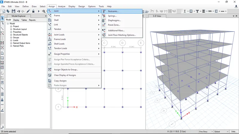
Goto joint select restraints
-
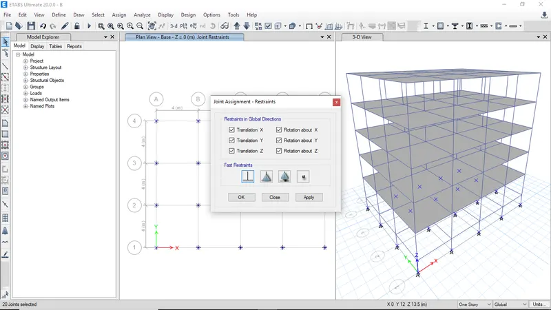
Now assign the fixed support to the joints then click ok
-
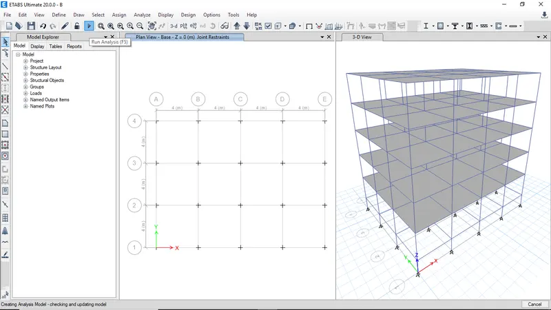
Click run analysis
-
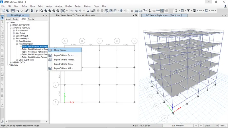
Select Modal periods table from structure output and right click and show table to view table
-
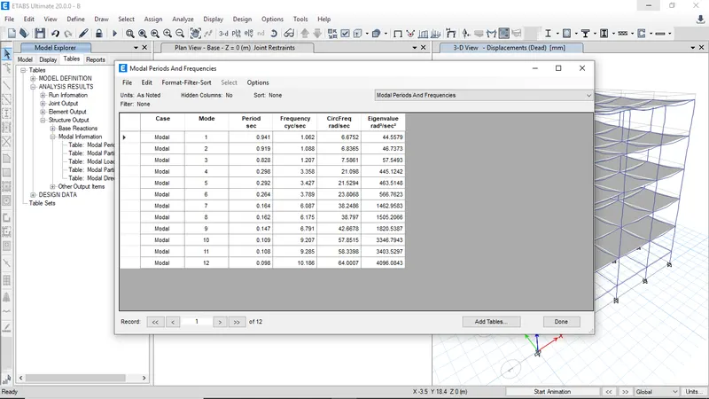
The modal periods and frequencies for Building B with Fixed support
Building H with 10% axial stiffness (Cross section area to 10%) -
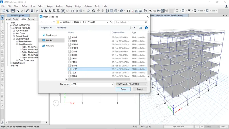
Open ETABS model of building H
-
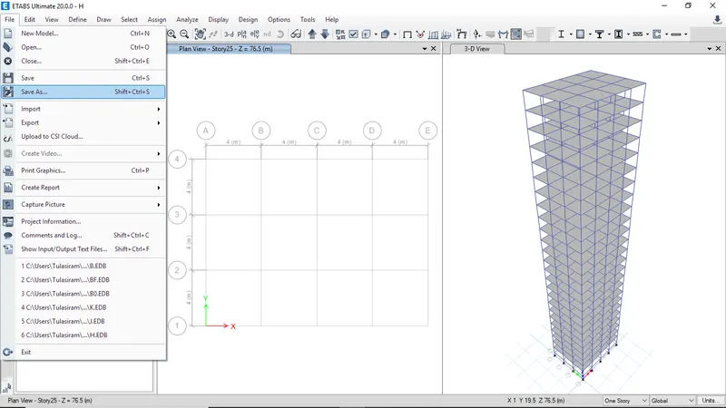
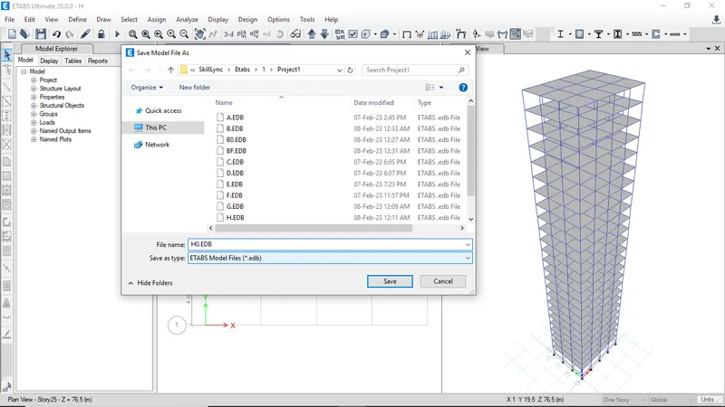
Click on save as to continue with same model
-
Enter name as H0 and click save
-
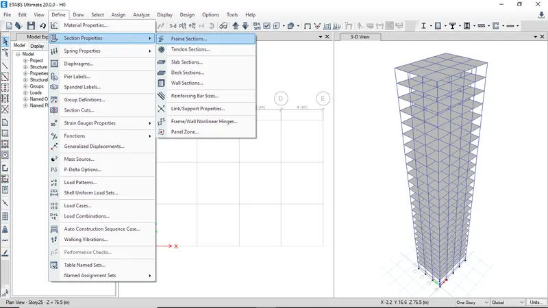
Goto define click on section properties and select frame sections
-
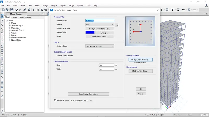
Now select Column C800x800 and click modify

-
Click on property modifier to modify axial stiffness
-
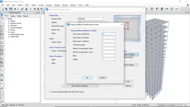
Enter cross section area 0.1 then click ok
-
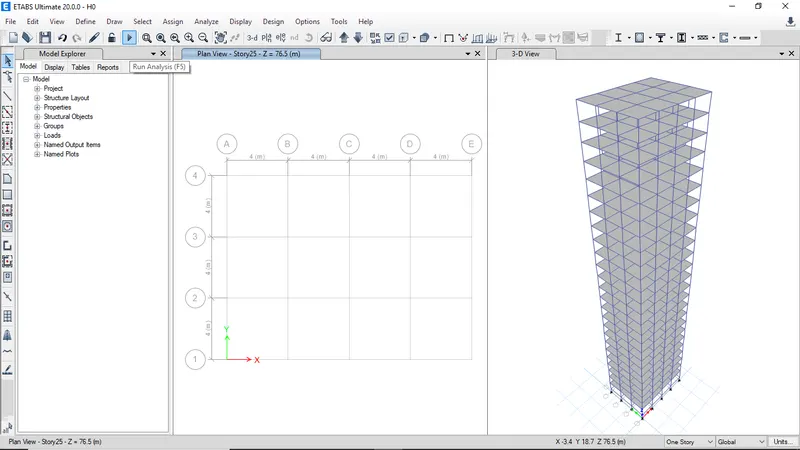
Now click Run analysis
-
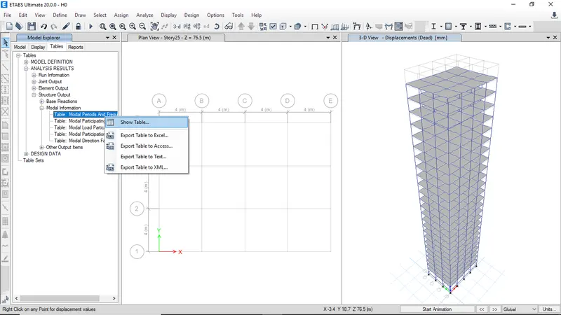
Select modal periods table from structural output and right click show table to view table
-
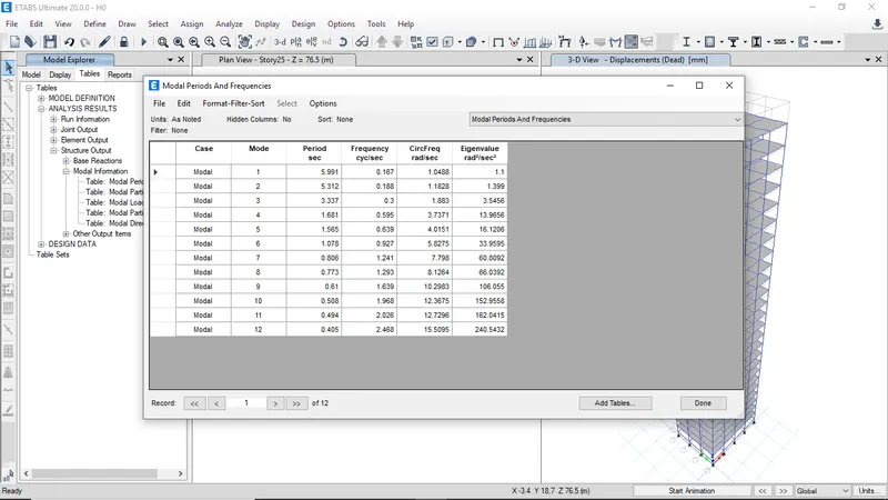
Modal periods and frequencies of Building H with 10% axial stiffness
RESULT
Factors influencing the Natural period of building
Effect of stiffness on natural time periodBuilding
No. of Storey
Column dimension
Natural time period
E
10
Upper 5 Story
400x400
1.732 s
Bottom 5 storey
600x600
F
10
600x600
1.735 s
G
25
Upper 5 storey
400x400
4.17 s
Middle 10 storey
600x600
Bottom 10 storey
800x800
H
25
800x800
4.416 s
For buildings E and F, varying column dimensions doesn't make a considerable difference because of only five stories. But, we can see considerable changes in case of buildings G and H, the building G has different column dimensions at different storey levels and building H consist of column dimension of 800x800 at all storeys which induces the more inertial mass at higher stories. Therefore, by reducing column size at higher stories we can minimise dead load which helps control the natural period 'T' for tall buildings.
Effect of mass on natural time period
Building
No. of storey
Imposed mass
Natural time period
H
25
3 kN/m2
4.416 s
J
25
3.3 kN/m2
4.425 s
K
25
3.6 kN/m2
4.435 s
By observing the results of analysis, the natural period for the tall buildings is directly proportional to the imposed mass of the building.
Effect of building height on natural time periodBuilding
No. of storey
Total Building height
Natural time period
A
2
7.5 m
0.5 s
B
5
16.5 m
1.036 s
F
10
31.5 m
1.735 s
H
25
76.5 m
4.416 s
From the analysis results we can observe the natural period is increasing with no. of storeys. So Natural time period is directly proportional to height of building
Effect of column orientation on time periodBuilding
No. of storey
Column dimension
Natural time period
B
5
400x400
1.036 s
C
5
550x300
1.145 s
D
5
300x550
1.12 s
The orientation of the column is also important factor which affects the stiffness of building. When the column cross-section is square, there's not much difference between the lateral displacement in both the orthogonal directions. However, in case of rectangular column the lateral displacement along larger dimension direction will be less than that in the other direction which has a lesser column dimension.
Effect of flexural stiffness of structural elements on mode shapeBuilding
Flexural stiffness
Natural period
B
100%
1.036 s
10%
2.627 s
On decrease the flexural stiffness of beams, the overall flexural strength of the beam is also going to reduce, and consequently, the fundamental natural period will shoot up.
Effect of axial stiffness of structural elements on mode shapeBuilding
Axial stiffness
Natural period
H
100%
4.416 s
10%
5.991 s
On decreasing the axial stiffness of column, the fundamental natural period of the building increases regardless of its structural geometry.
Effect of degree of fixity at column on mode shape
The pinned support restraints only translational movements not rotation but fixed support restrains all the moves and rotations which leads to more movement and thus increased natural period. As a result, it can be concluded that the fixed support will give you better control over the fundamental natural period of buildings.Building
Fixity at column base
Natural period
B
Pinned
1.036 s
Fixed
0.941 s