Project 1_Comparative study of different storey buildings for Seismic forces
Project 1 - Comparative study of different story buildings for Seismic forces
AIM:- To Compare the results of different - different-story buildings for some given conditions and parameters.
INTRODUCTION:- In the project, we compare the different - different-story buildings for a given condition and try to find out the conclusion.
Given the Parameters of the building:-
Structural Element Sizes
- Beams: 300 × 400 mm
- Columns: 400 × 400 mm
- Slab: 150 mm thick
Material Properties
- Grade of Concrete: M30
- Grade of Steel Reinforcement Bars: Fe 415
Loading
- Dead Load on beams from infill wall: 10 kN/m
- Live load on the floor : 3 kN/m2
(what is the seismic mass?)
- Buildings are assumed to be pinned at the base
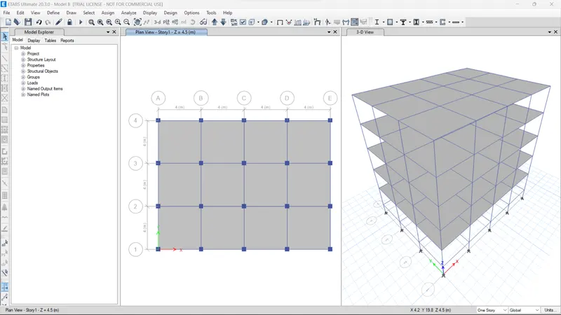
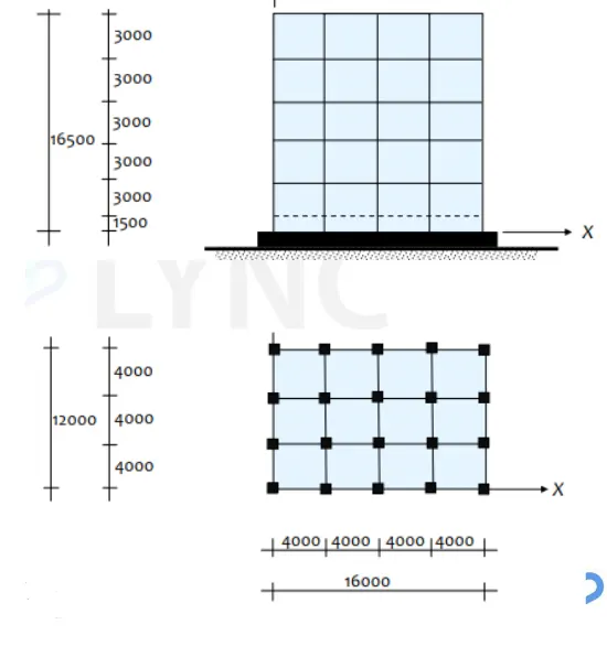
Five-storey Benchmark Building: Elevation and plan of benchmark building showing the structural moment frame grid (All dimensions are in mm)
Various Building Description and their conditions:-
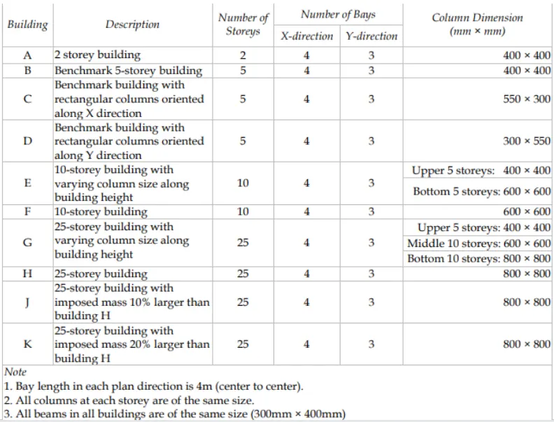
List what we try to find out in these analyses and compare these results with each other as per such conditions:
- Effect of stiffness on T: Compare fundamental natural periods of buildings E & F as well as G & H. Why is there a marginal or significant difference in the fundamental natural periods?
- Effect of mass on T: Compare fundamental natural periods of buildings H, J and K. Have the buildings become more flexible or stiff due to change in mass?
- Effect of Building Height on T: How do the fundamental natural periods of Buildings A, B, F, and H change with a change in building height?
- Effect of Column Orientation on T: How do the fundamental natural periods of Buildings B, C, and D change with a change in column orientation?
- Effect of Flexural Stiffness of Structural Elements on mode shapes: Compare the fundamental mode shape of Building B in two situations when the flexural stiffness of beams relative to that of adjoining columns is very small versus when it is large.
- Effect of Axial Stiffness of Vertical Members on mode shapes: Compare the fundamental mode shape of Building H in two situations when the axial cross-sectional area of columns is very small versus when it is large.
- Effect of Degree of Fixity at column bases on mode shape: Compare the fundamental mode shape of Building B in two situations when the base of columns is pinned versus when it is fixed.
PROCEDURE:-
MODAL-A
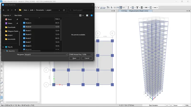
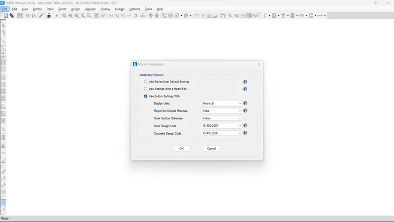
First, go to the new model
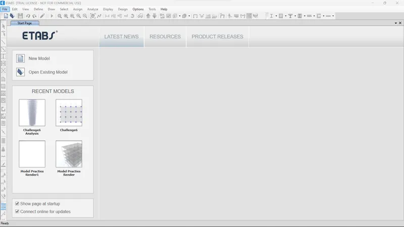
select parameters
Display units- Metric SI
Default materials - India
Steel section database - Indian
Steel design code - IS-800-2007
Design code - IS-456-2000
Press ok
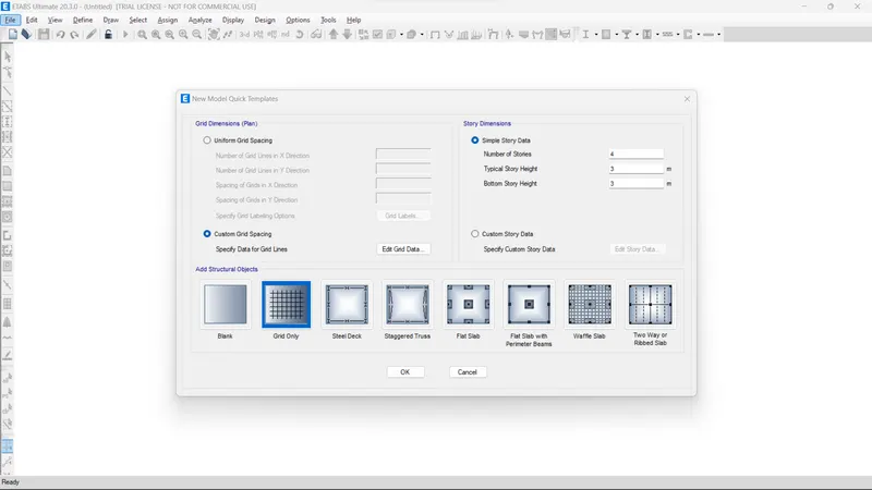
Custom grid spacing and Story data
Goto Edit Grid data
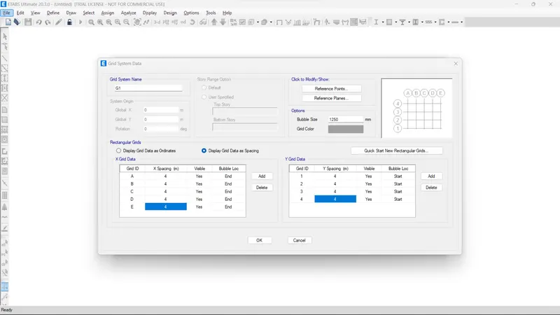
First Add 5 grids along x-direction @ spacing of 4m
Second Add 4 Grids along the Y-direction @ spacing of 4m
Press ok
Then goto Edit story data
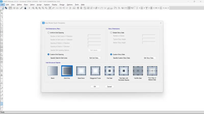
In first project name Model A Is only two stories @ of 3m in Height
And Base to plinth level height is 1.5m
Assign the Master story as Story 1
Assign Similar all story to story 1
Press ok
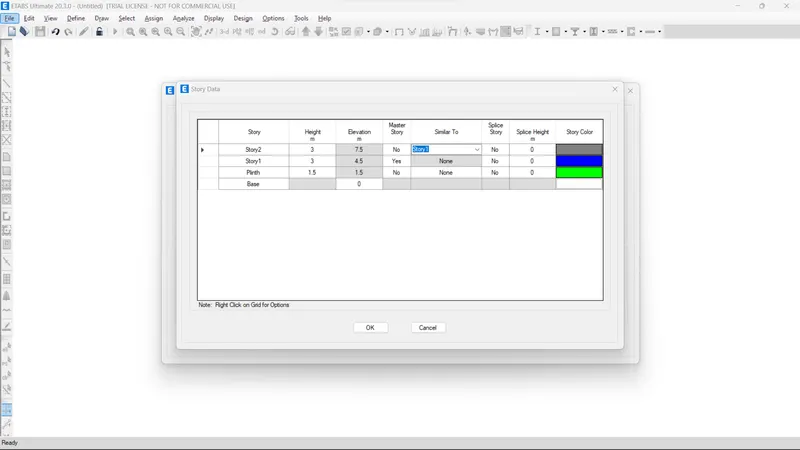
Everything is done then press ok

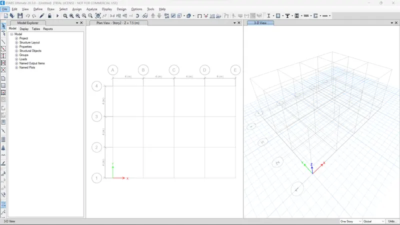
Define Materials like concrete grade, Grade of reinforced bars, Loads and Load combination, Slab
Goto to Material properties
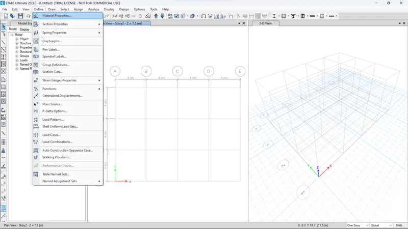
Add new materials
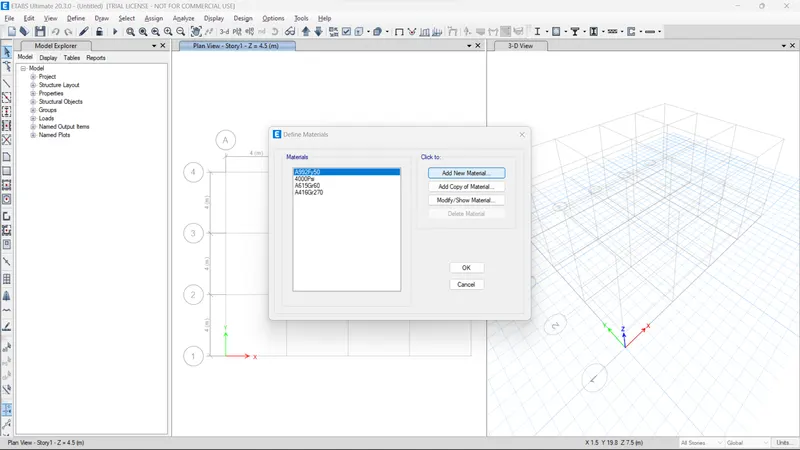
Define parameters
Region-India
Material type- Concrete
Standard - Indian
Grade-M20
press ok
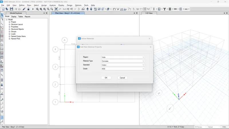
Select material type - Concrete
Press ok
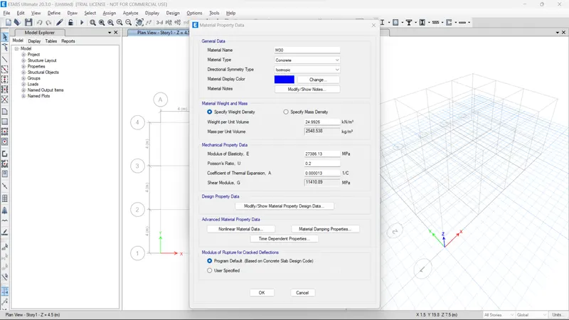
Add Another material
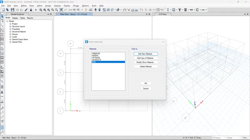
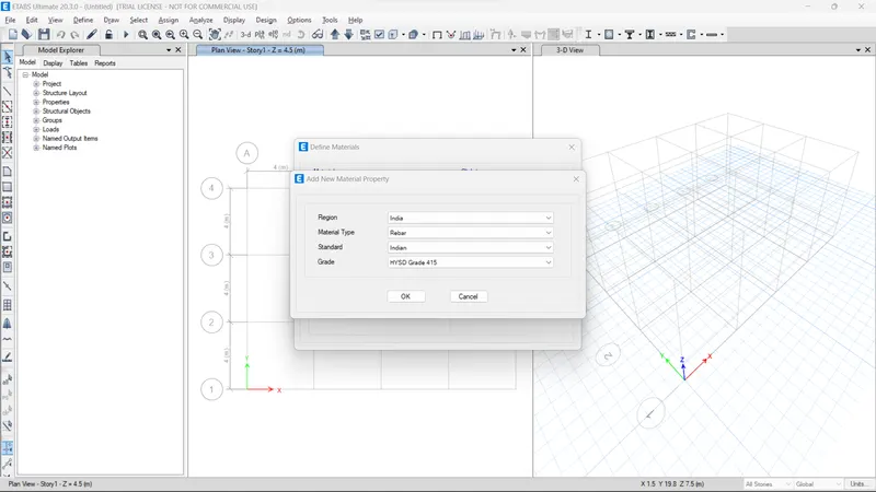
Define parameters
Region-India
Material type- Rebar
Standard - Indian
Grade- HYSD-415
press ok
Select Material type- Rebar
press ok
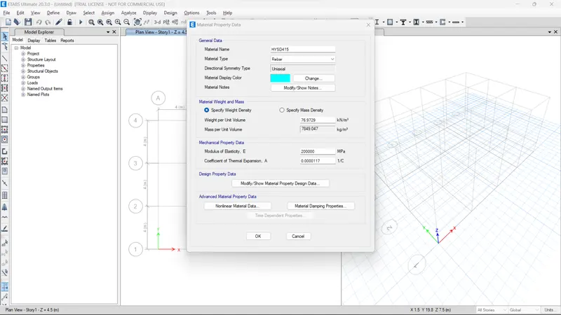
Press ok
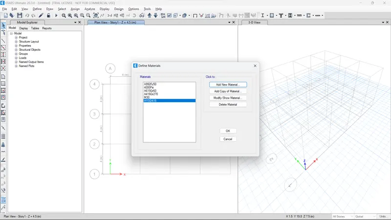
Next, Define the Beam and Column
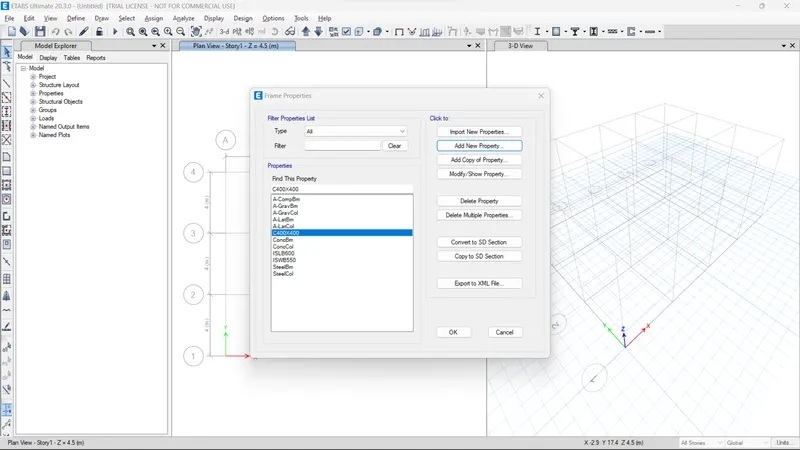
Goto define> section properties> Fame Section
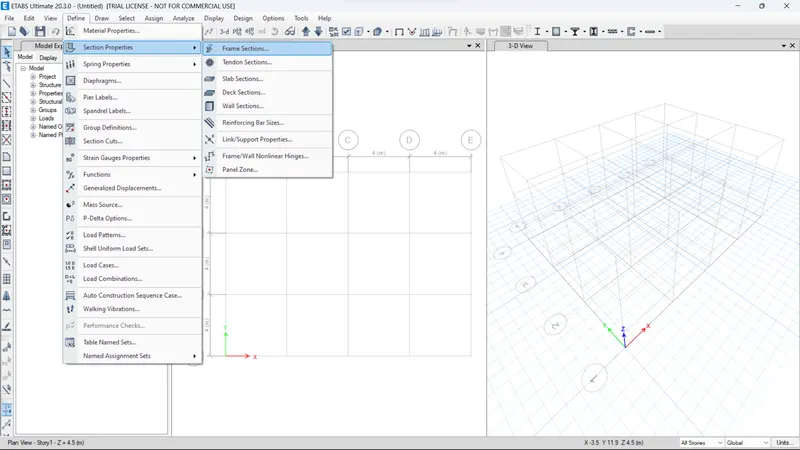
Add new property
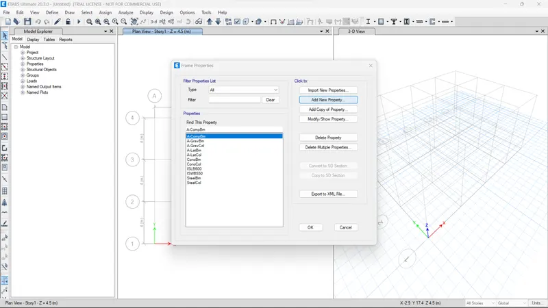
Select a rectangular shape section
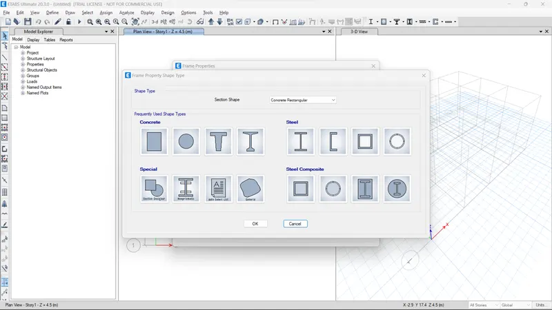
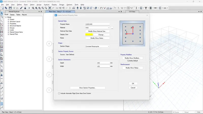
Define parameters
Property name - C400X400
Material- M20
Depth- 400mm
Width- 400mm
Then to modify rebar
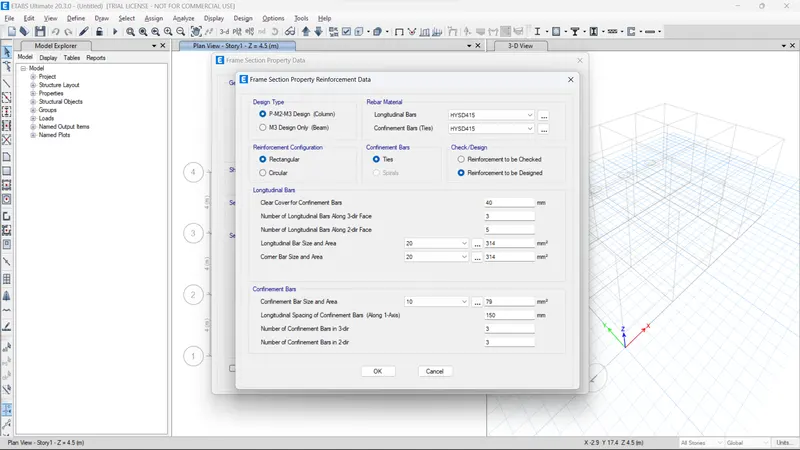
Select parameters
Define type - Column
Rebar materials- Both Longitudinal and ties bars -HYSD 415
Press ok
Press ok
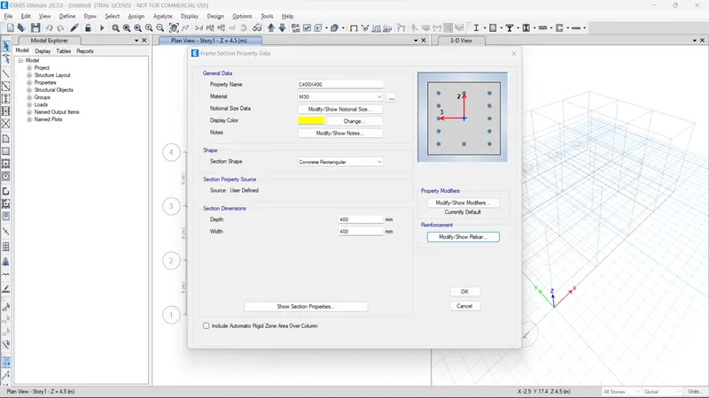
Again Add a new property for the beam
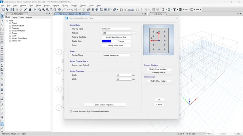
Define parameters
Property name - B300X400
Material-M20
Depth-400mm
Width-300mm
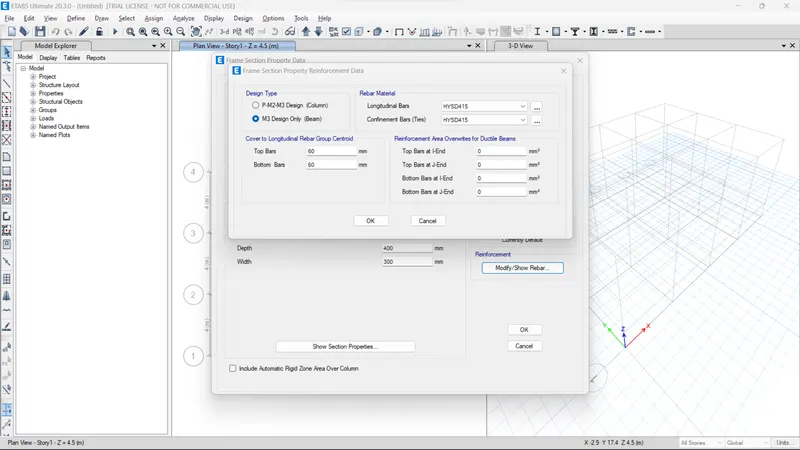
then goto modify the rebar
Define type-Beam
Rebar materials- Both Longitudinal and ties bars -HYSD 415
Press ok
Press ok
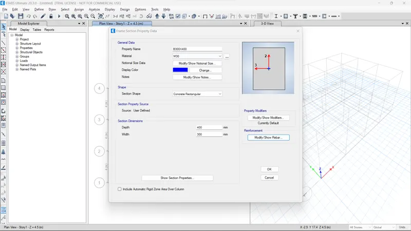
Press ok
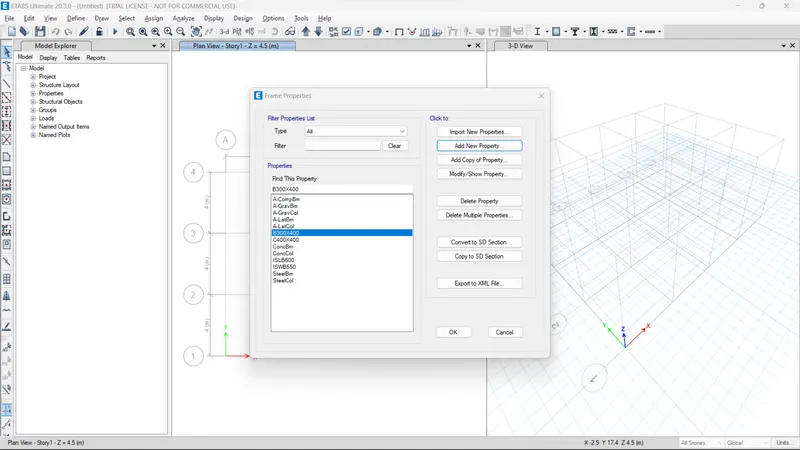
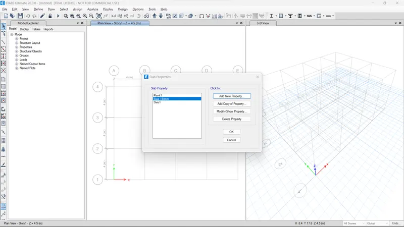
Next, define slab 150mm thick
Goto Define> section properties> slab section
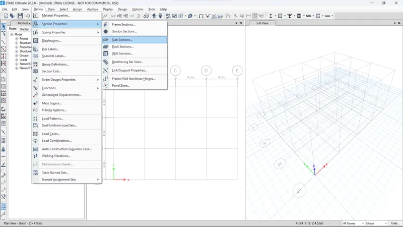
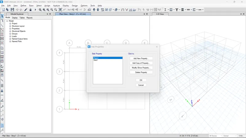
Add new property
Define parameters
Property name - Slab 150mm
Slab material - M30
Modeling type - Membrane
Thickness - 150mm
press ok
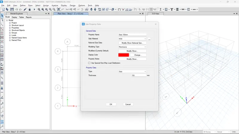
press ok
Then Define loads and combination
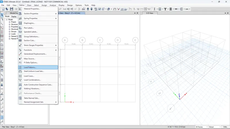
Goto define> Load patterns
Add new load
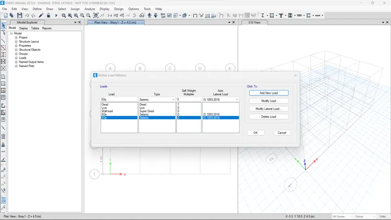
Load - Type - self-weight - Auto lateral load
Dead - Dead - 1 - _
Live - Live - 0 - _
Wall load - super load - 0 - _
EQx - Seismic - 0 - IS 1893-2016
EQy - Seismic - 0 - IS 1893-2016
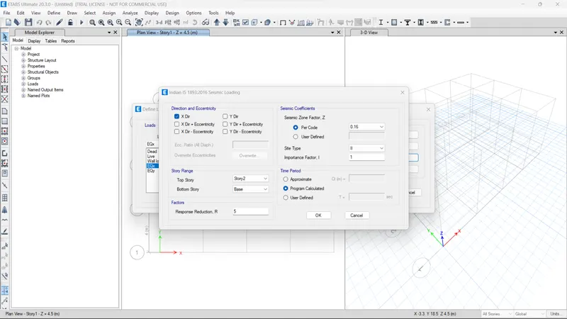
Modify lateral load
Direction only- X Dr
Seismic zone factor - 0.16(II)
Everything is default
Press ok
Direction only- Y Dr
Seismic zone factor - 0.16(II)
Everything is default
Press ok
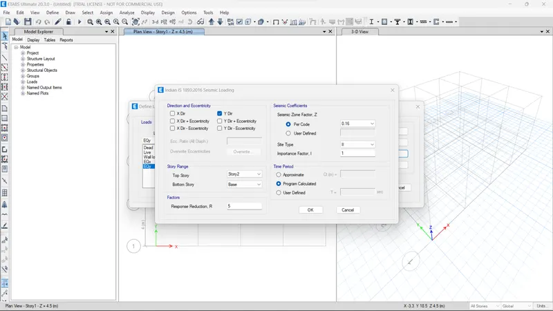
Press ok
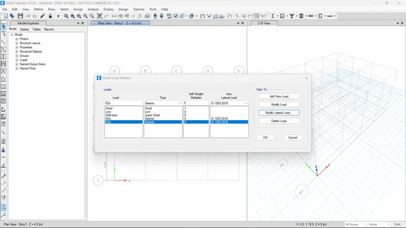
Check load is defined or not
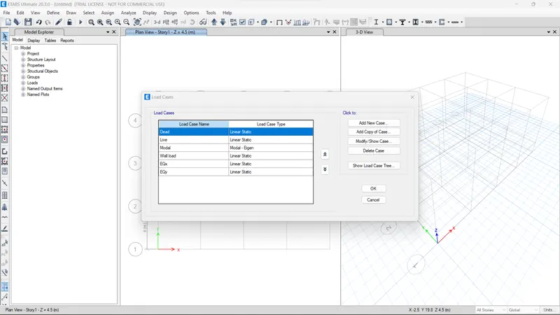
Goto define> Load case > check ok > press ok
Add load combination
Goto Define> load combination
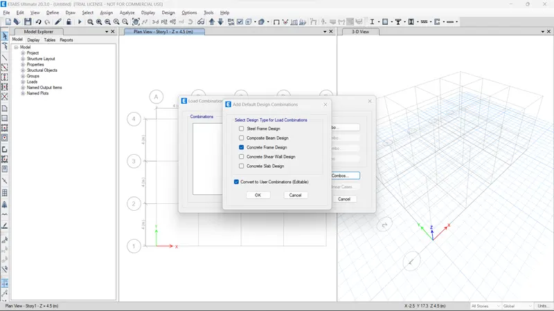
Select Add default design combos
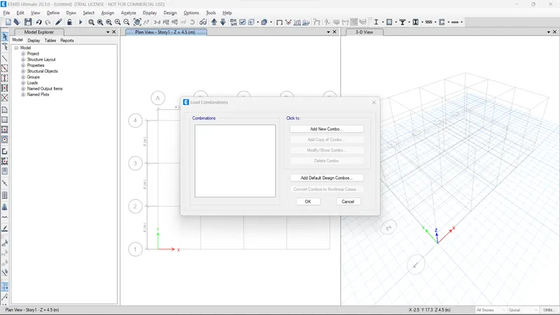
Select Concrete Frame Design
press ok
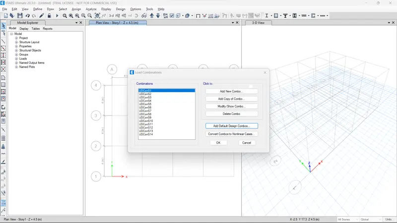
The auto combination is created as per IS 1893-2016
Press ok
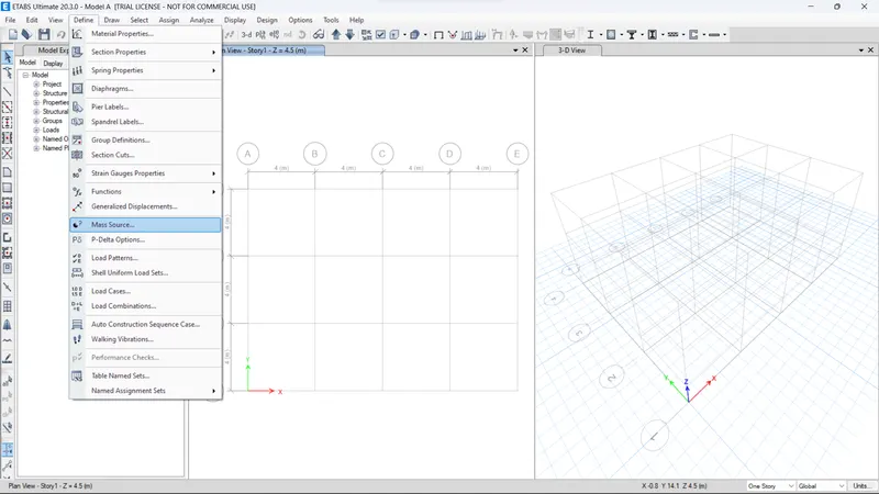
Define Mass sources
Got to define> Select Mass Sources
Select mass sources > Modify mass Sources
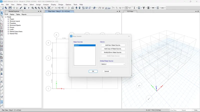
Select the specified load pattern
Add load
Live - 0.25 (Multiplier)
Dead - 1 (multiplier)
Wall load - 1 (Multiplier)
Press ok
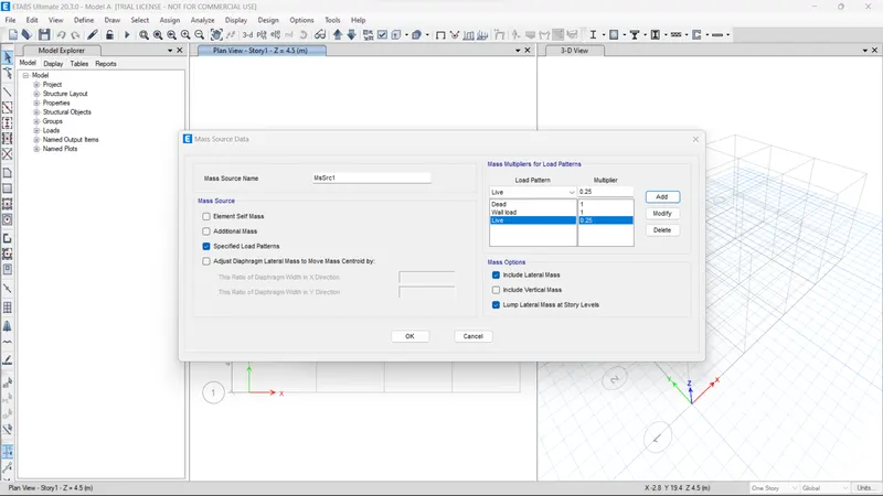
Press ok
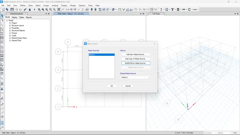
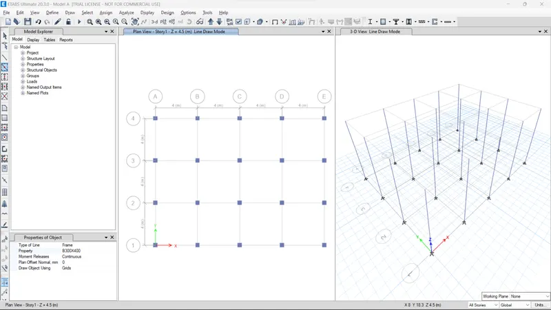
Now Assign columns, beams, and slabs to their places
Select quick Sketched columns
Select column property -C400X400
The select crosssection of Other direction grids
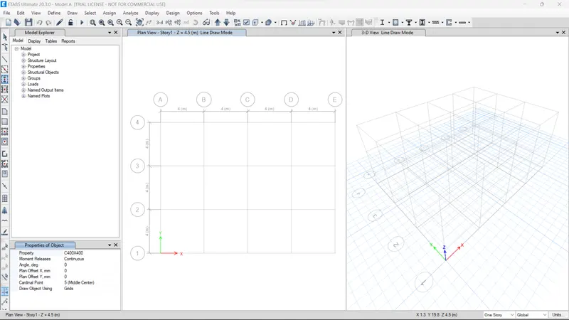
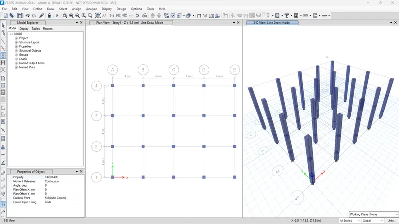
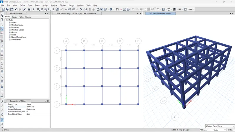
Select quick Sketched beams
Select Beam property -B300X400
Place beams between columns
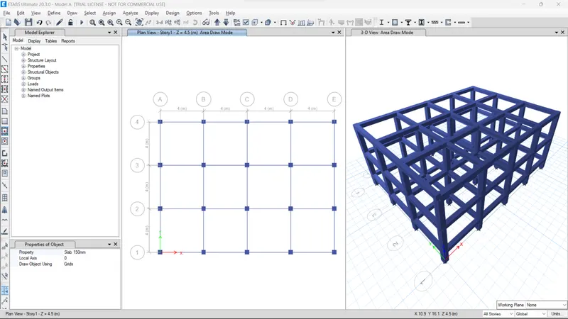
Assign slab
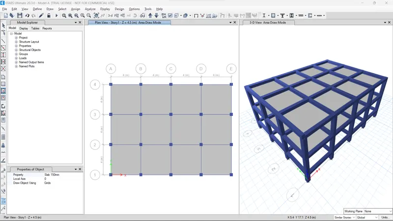
Select quick draw floor sketched
Select property- Slab 150mm
Rectangular portions are selected and slabs are defined
Define Slab at Story 1 to Story 2(Select similar story option)
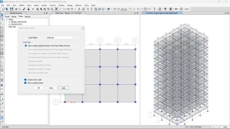
Assign loads in frames
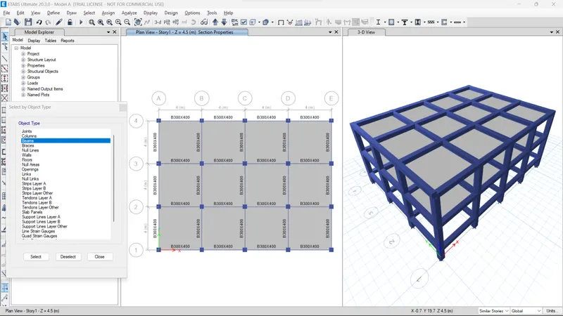
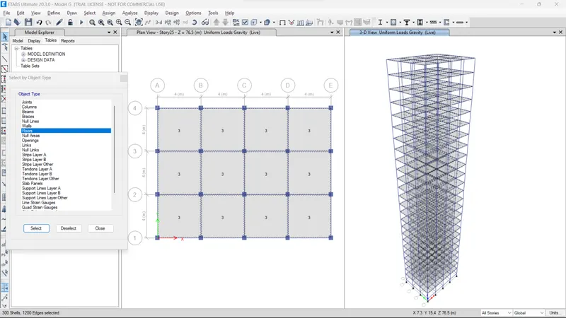
Goto Select by Object type
Select beams
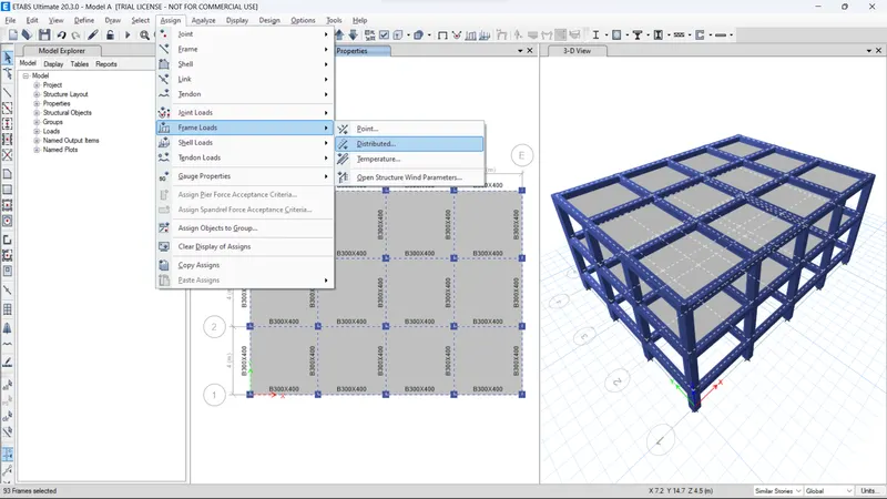
Goto Assign > Frame Loads> Distributed
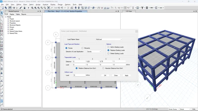
Select Wall load
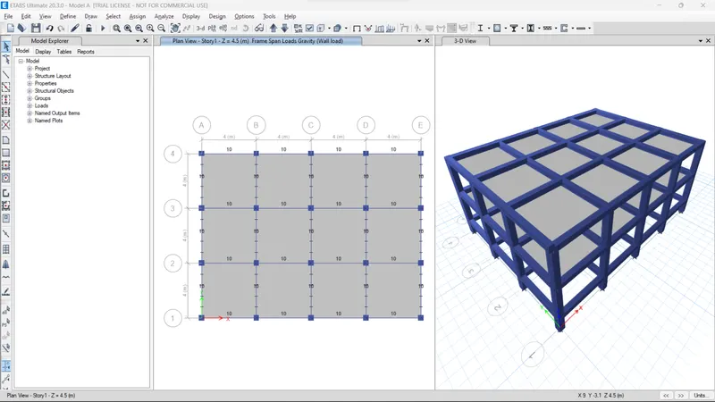
Load - 10KN/m
Press Apply
Goto Select by Object type
Select Columns
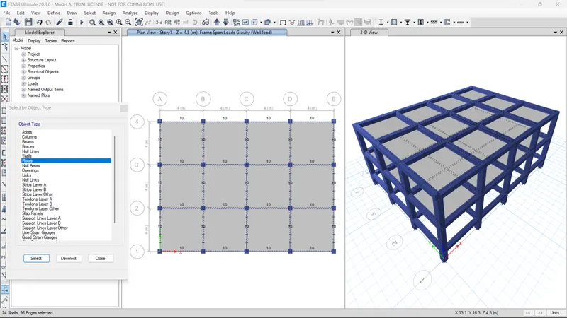
Goto Assign > Frame Loads> Distributed
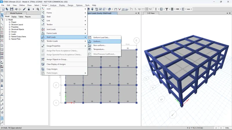
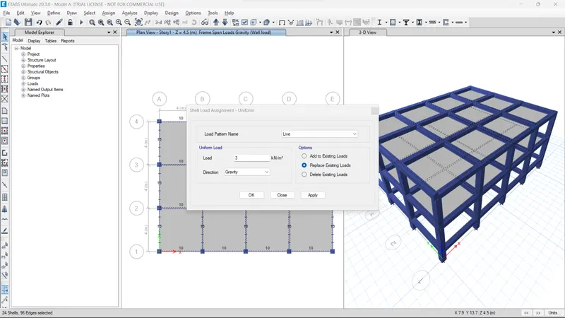
Select Live load
Load - 3KN/m
Press Apply
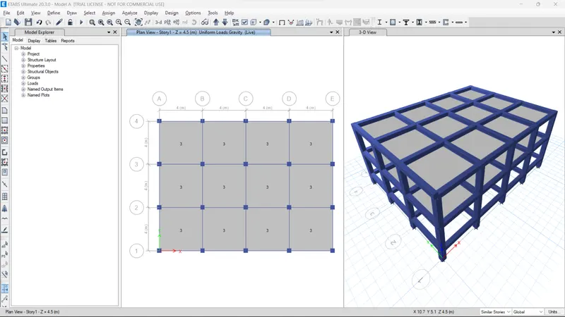
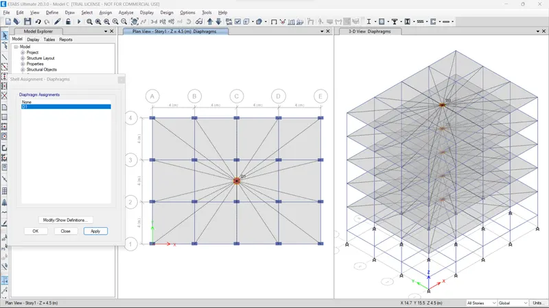
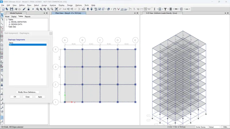
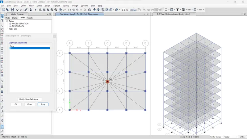
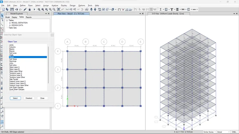
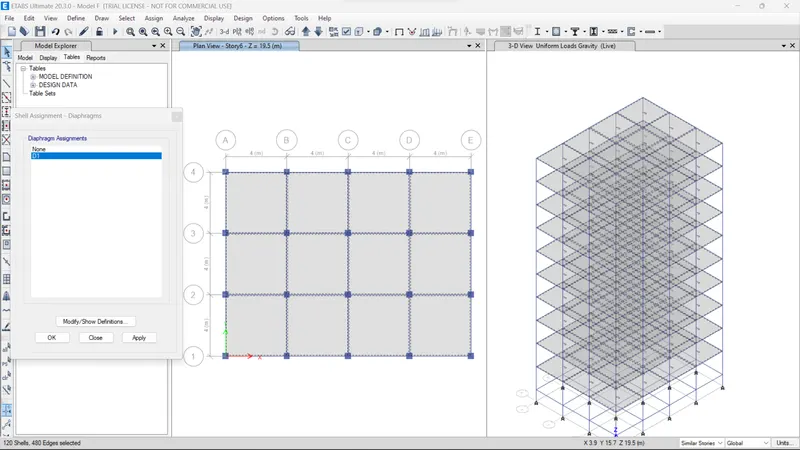
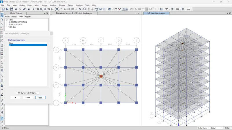
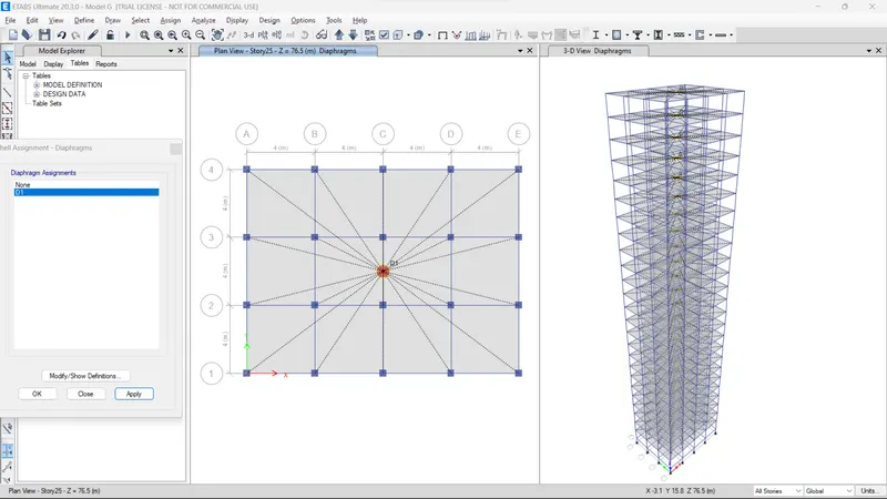
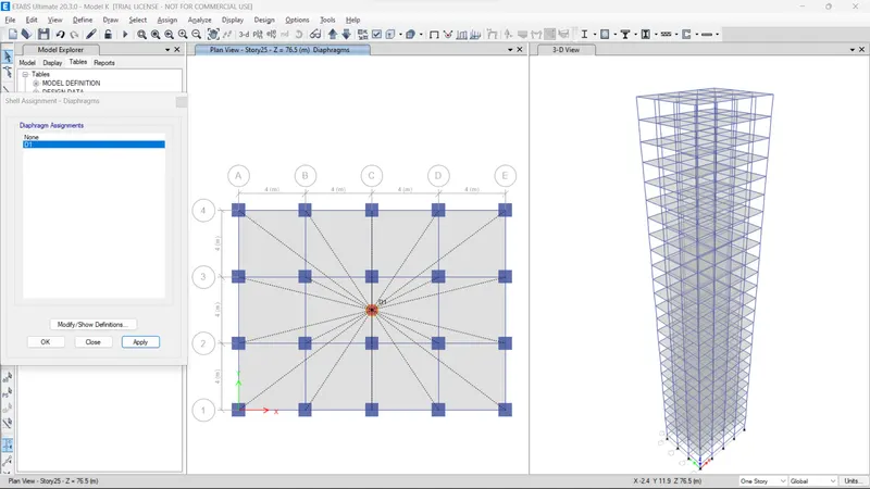
Define Diaphrmgrms
Goto Select by Object type
Select Frames
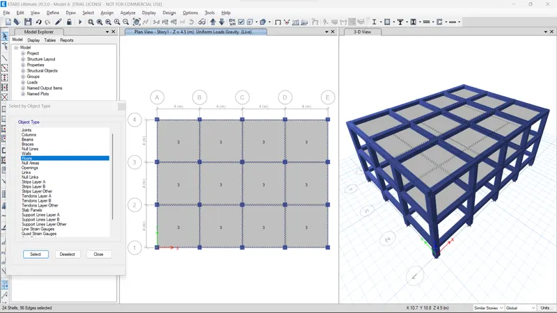
Goto Assign> select shell> Disphragrms
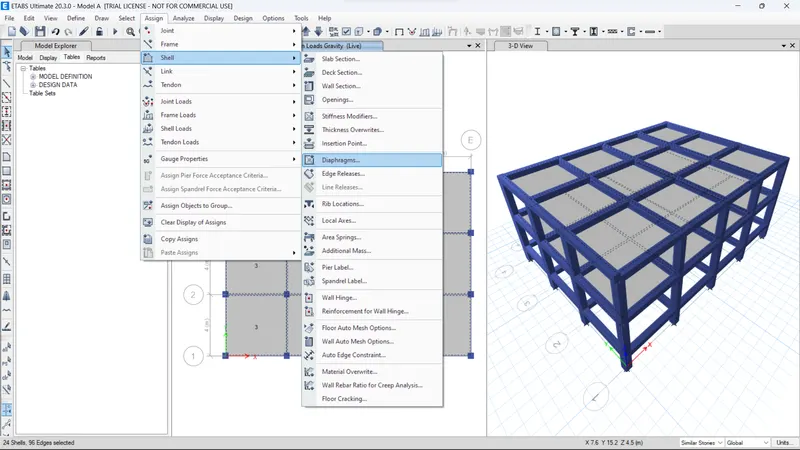
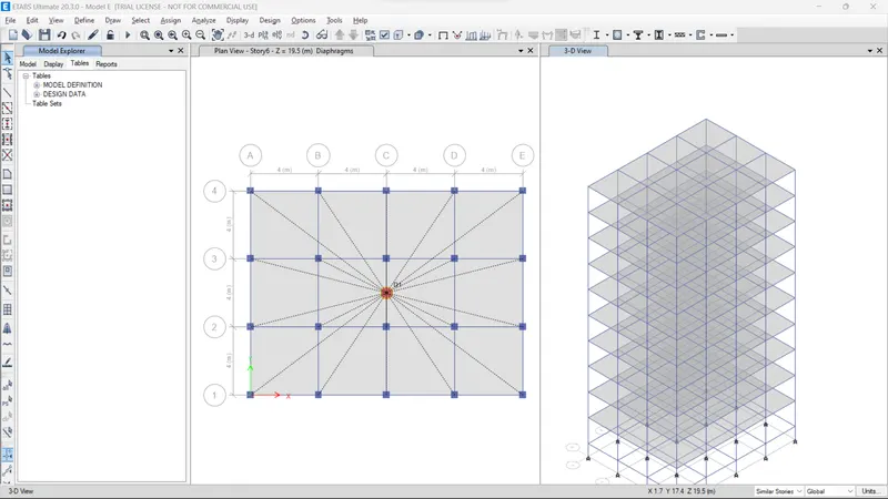
Select D1 > press apply
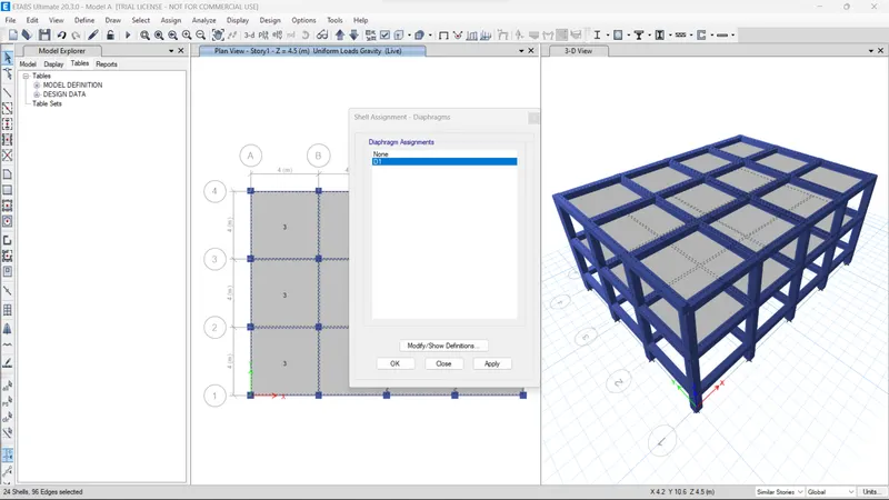
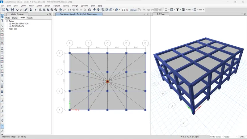
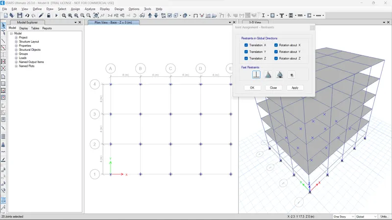
The select base of all column's bottom
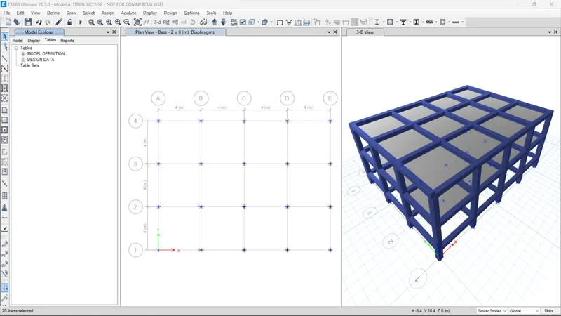
Assign supports
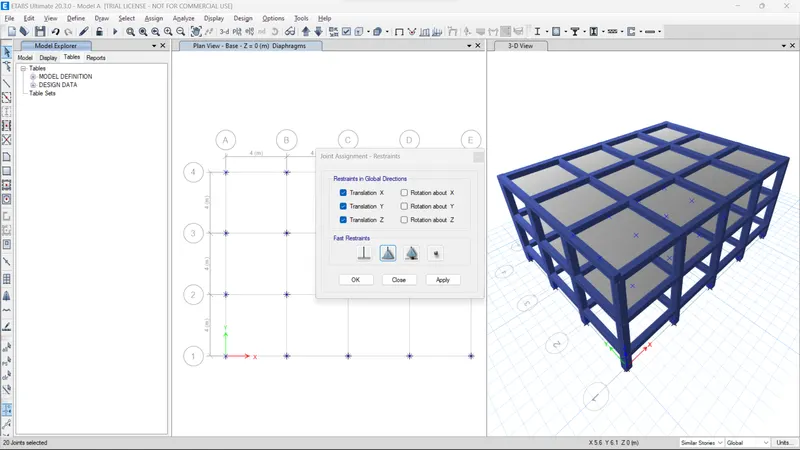
Goto Assing > joint > Restraints
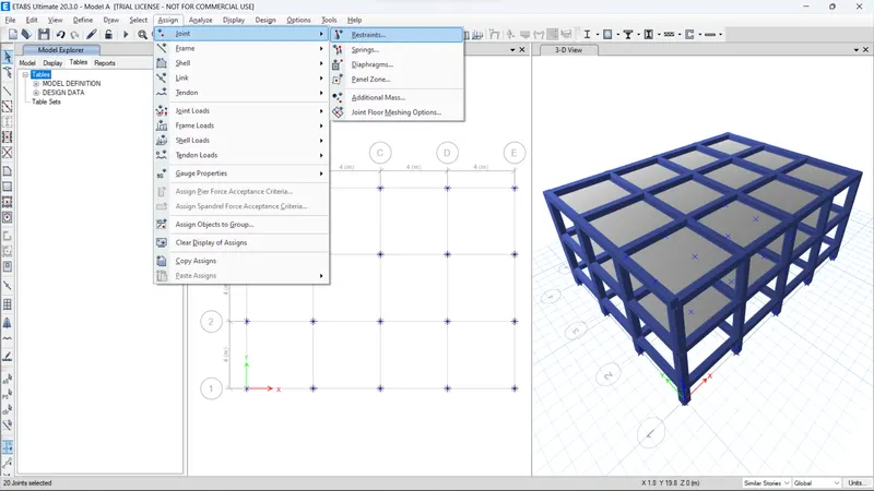
Select Pin Support> Apply
Run Analysis
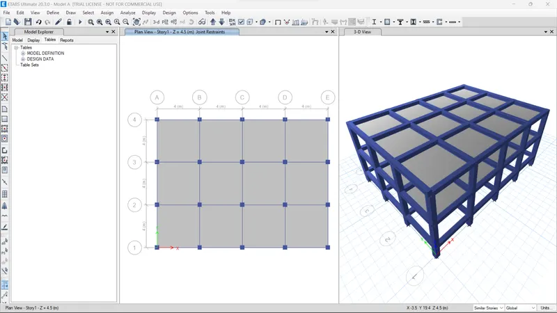
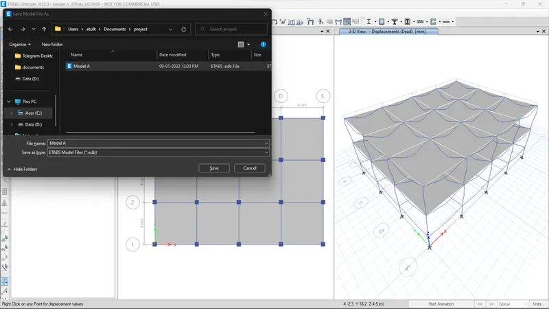
Save the Model AS Model A
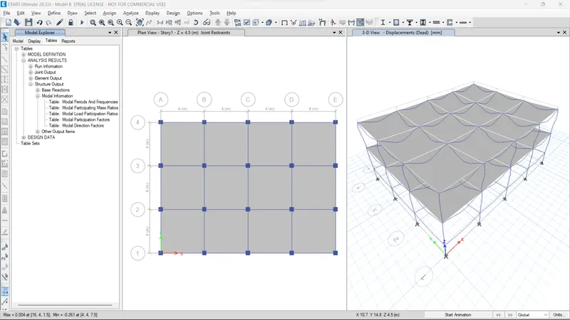
Results are Available
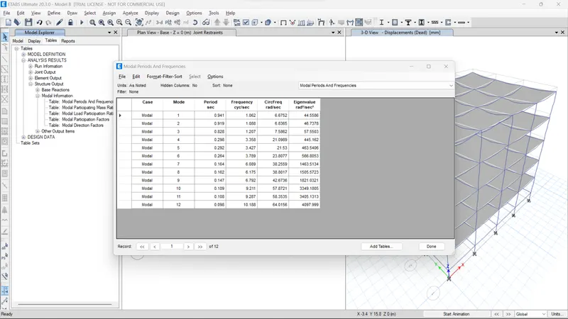
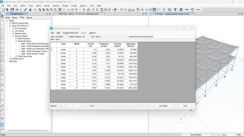
Model Periods and Frequencies
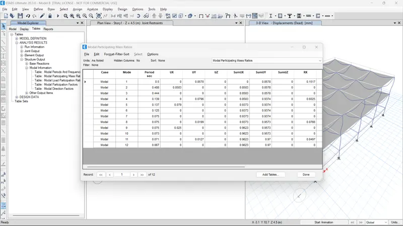
Modal PArticipating Mass Ratio
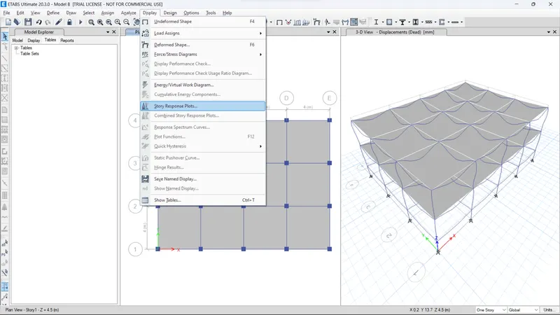
Goto Dispaly> Story Response plots
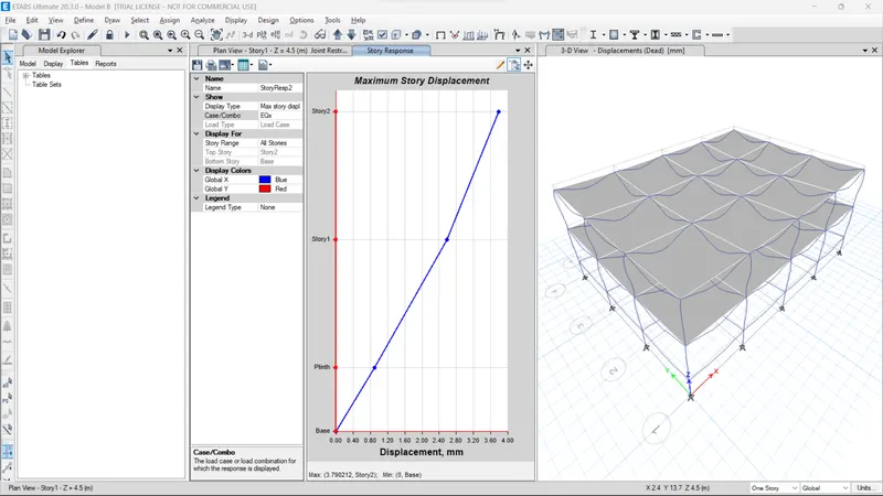
Maximum Story Displacement along EQx
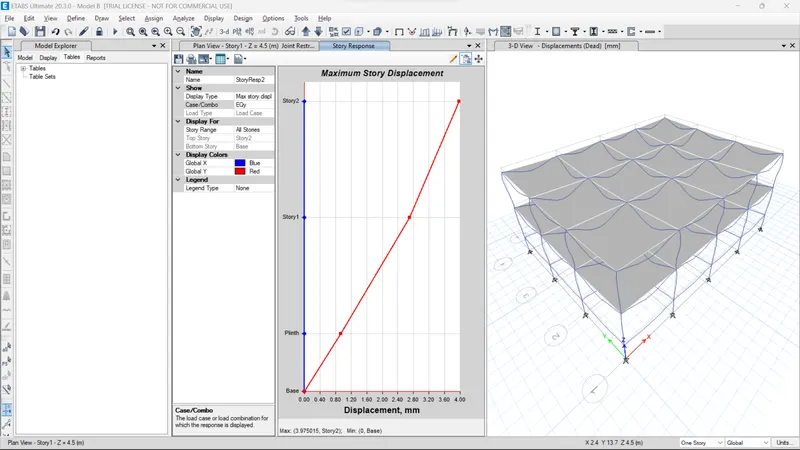
Maximum Story Displacement along EQy
Save Modal A as Modal B (Because Grids, Story Height, load cases, And other parameters are similar)
Change Add 3 more story
Goto Edit> Edit stories and Grid systems
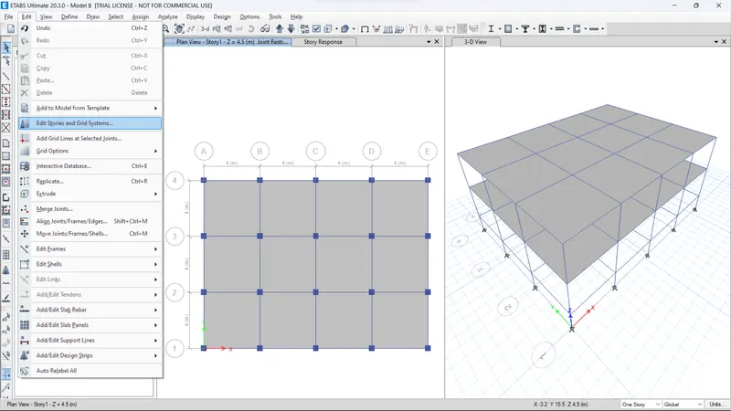
Goto to Modify Story data
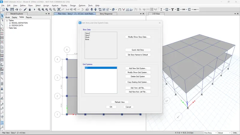
Add # story above story 2 and similar to story 2
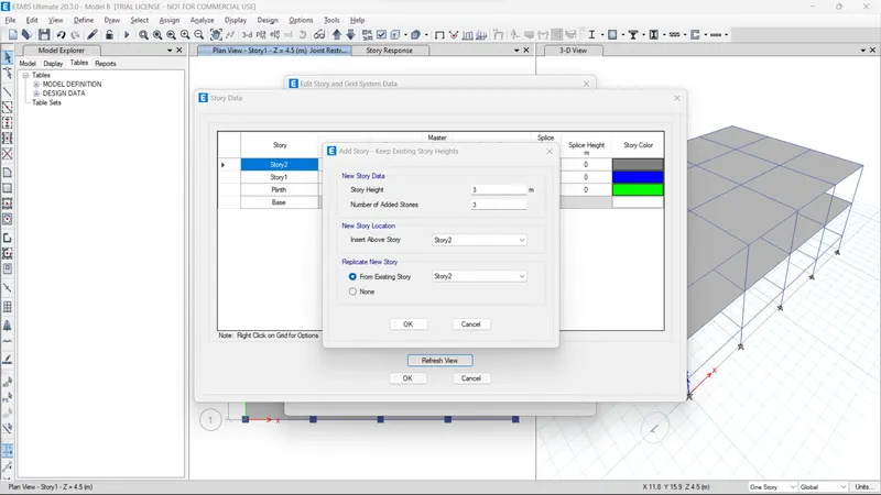
Select all stories similarly to story 1
And Refresh view
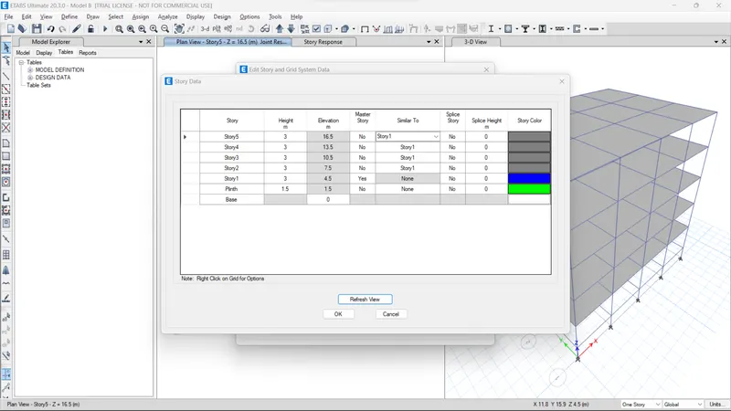
Press ok
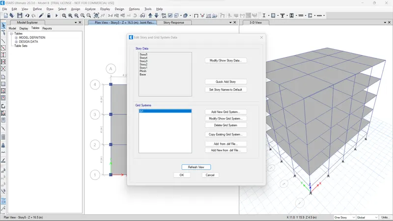
Showing load which is already applied and Disphargram
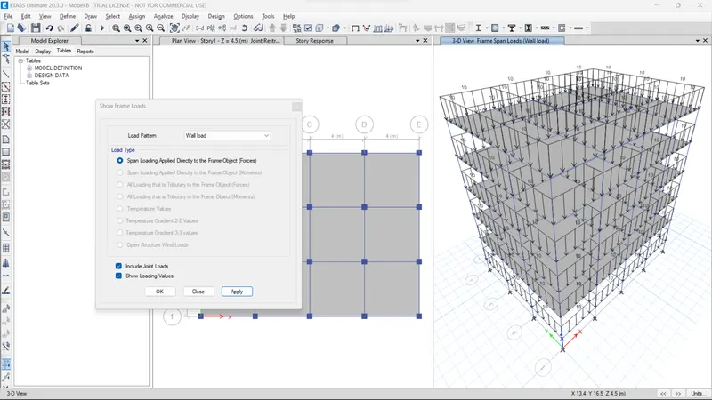
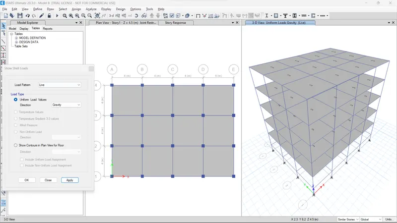
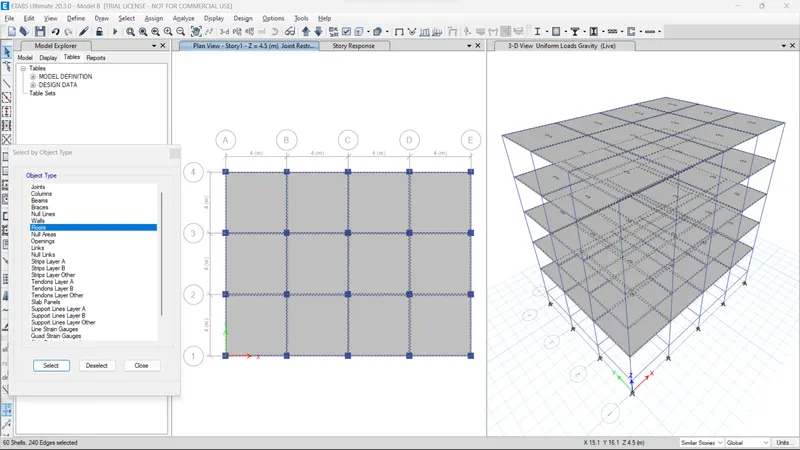
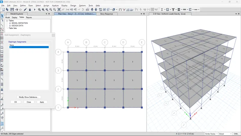
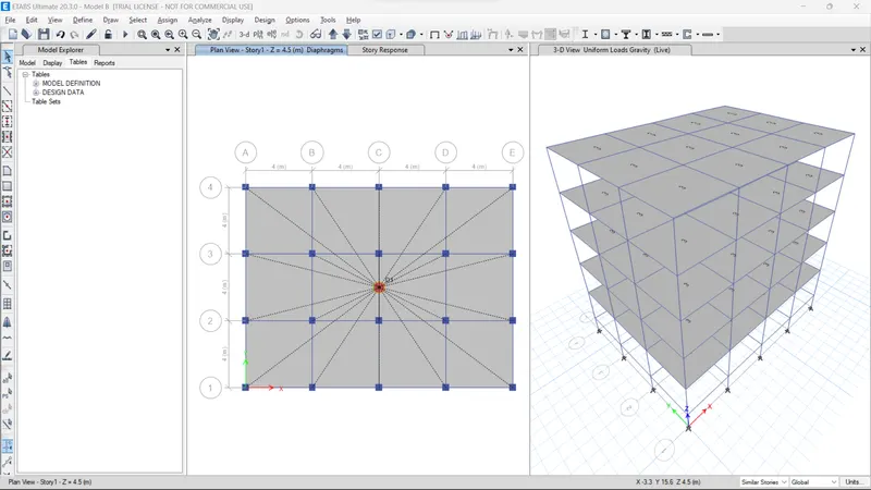
So directly run analysis
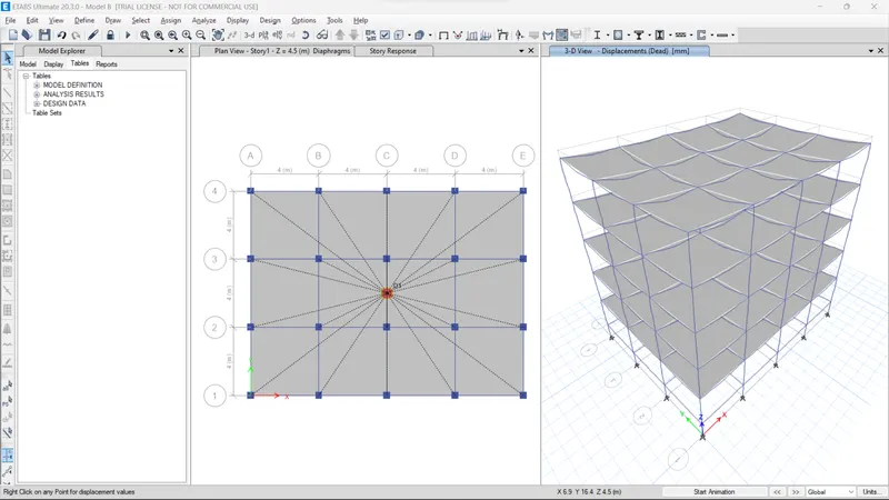
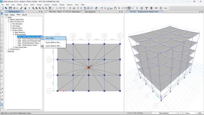
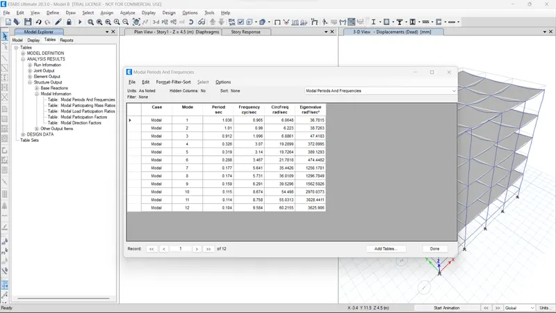
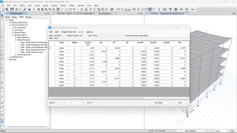
Results of modal B
Modal periods and frequencies
Modal participating mass ratios
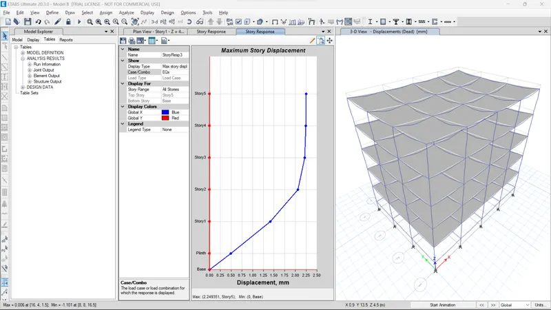
Maximum story displacement along EQx
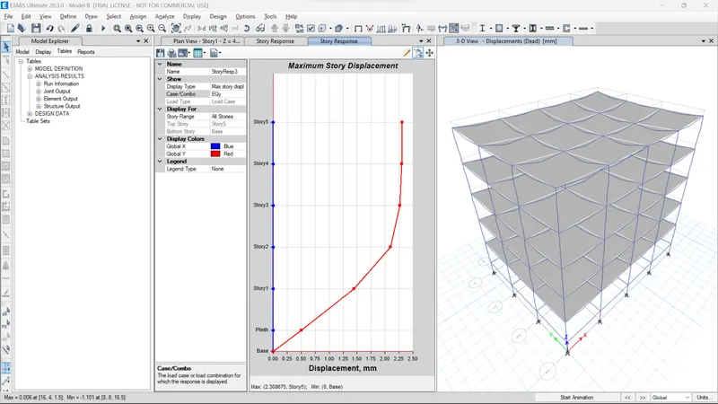
Maximum story displacement along EQy
MODAL-C
Save Modal B as Modal C (simply make a copy) (Because Grids, Story Height, load cases, And other parameters are similar)
Changes of modal C is only the size of the column is changed -C 550x300 Along X-direction orientation
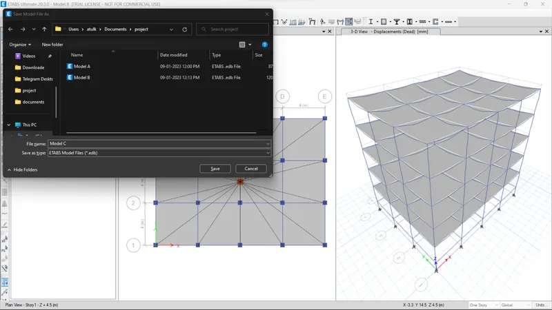
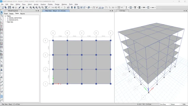
Define New column size
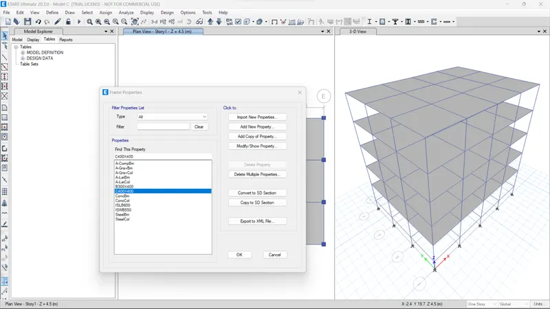
Goto define> select frame properties
Add new properties
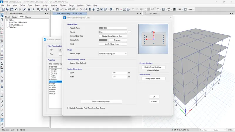
Define Property
Property name - C550X300
Material - M20
Depth-330mm
Width- 550mm
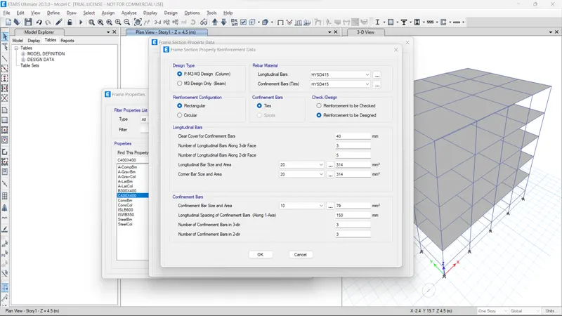
Goto Modify rebar
Select column
Rebar material - Both Longitudinal and ties - HYSD415
Press ok
Press ok
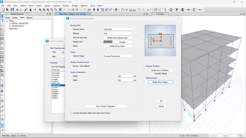
Press ok
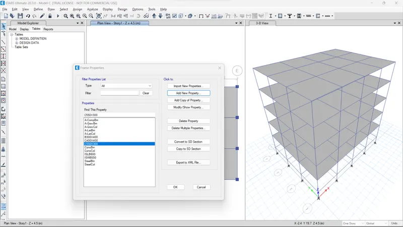
Next, assign the column or replace the previous column with new columns
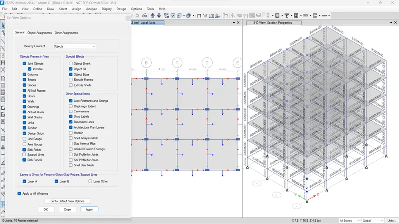
Goto View> Set display options
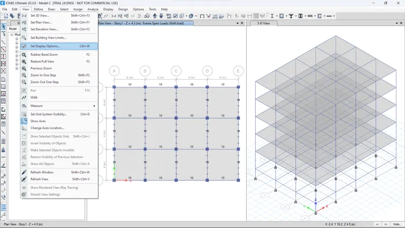
Deselect beams and floor
press ok
Select entire Columns
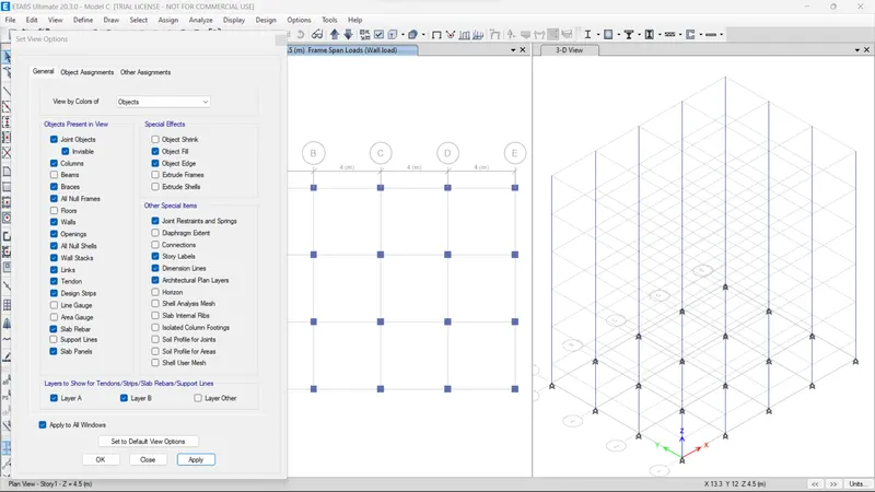
Then Goto Assign> select Fram > section property > select C550X300> press ok
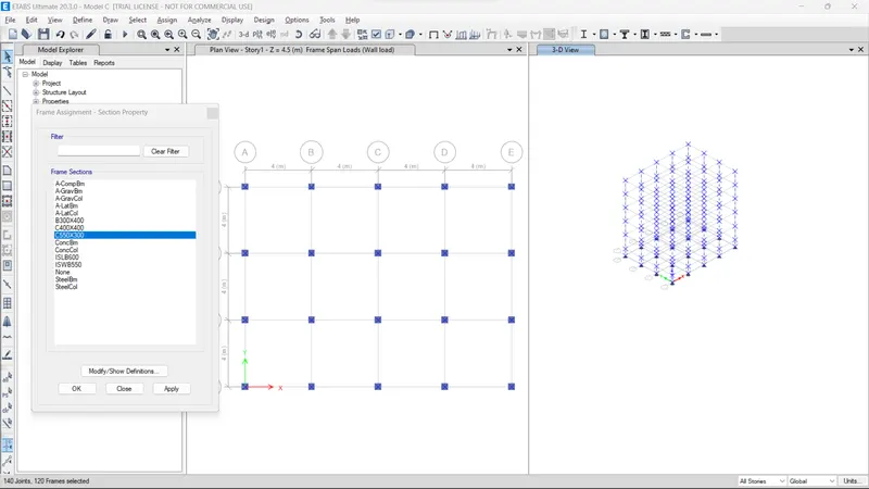
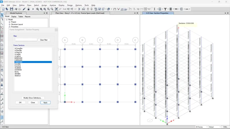
In question, Column are oriented along X-direction
So go to Assign > Local axes
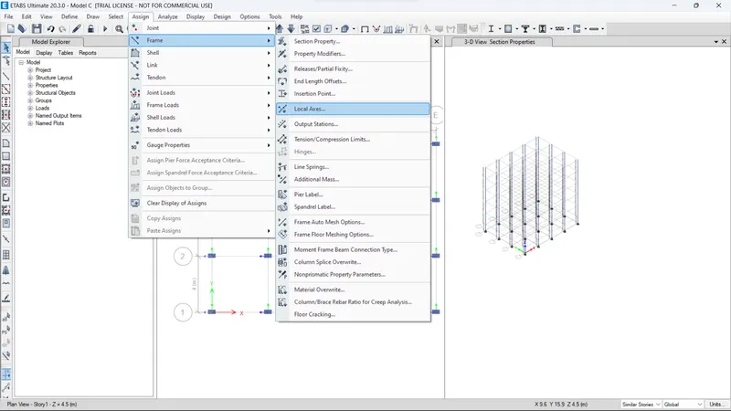
Select angle -90 degree
Press Apply
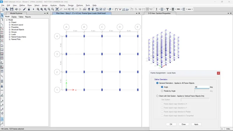
Again open the set view option
select beam and floor
Press Apply
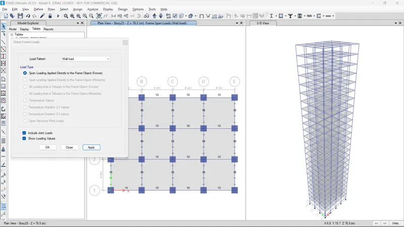
All Live and wall load is already applied
Apply diaphragm
And Run analysis directly
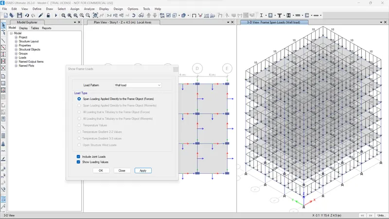
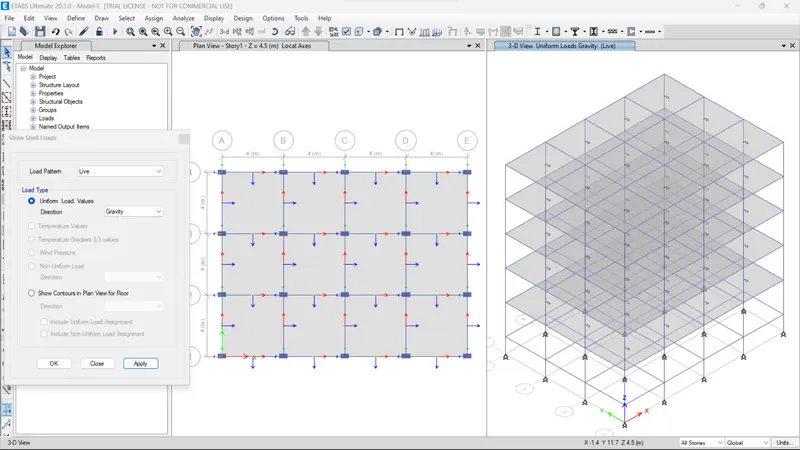
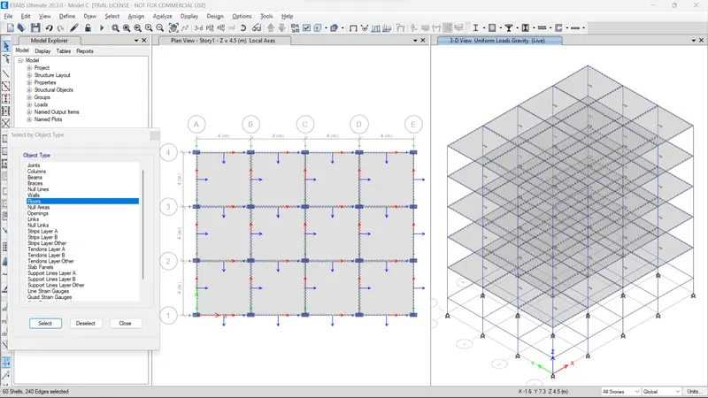
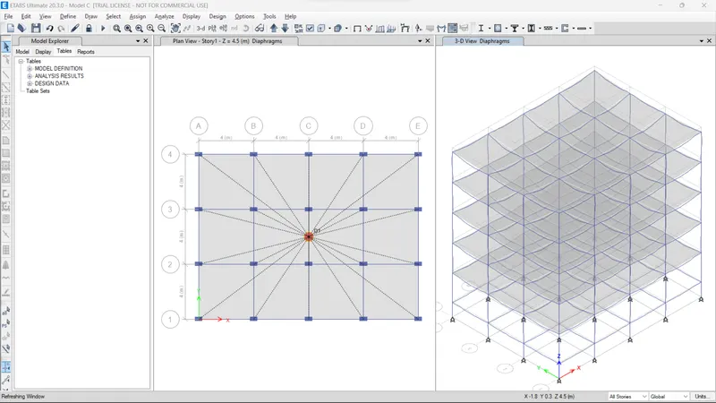
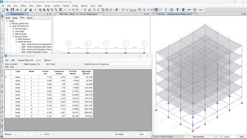
Result of Modal C
Modal period and frequencies
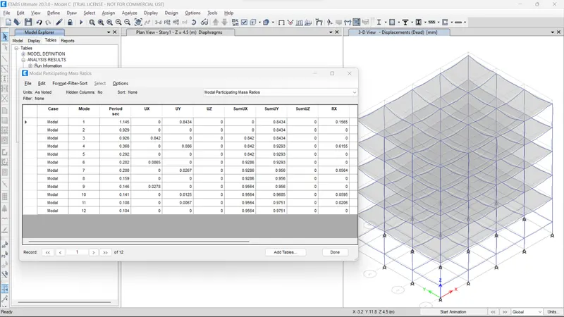
Modal participating mass ratios
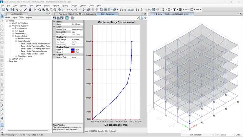
Maximum story displacement along EQx
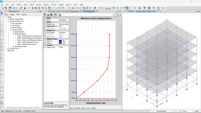
Maximum story displacement along EQy
MODAL-D
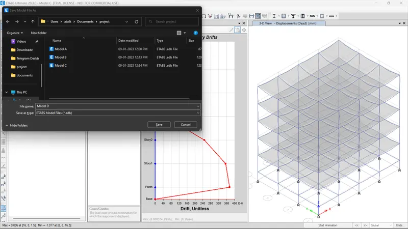
Save Modal C as Modal D (simply make a copy) (Because Grids, Story Height, load cases, And other parameters are similar)
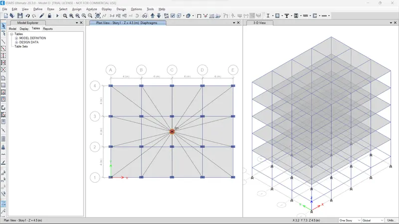
Changes of modal D is only the size of the column is changed -C 300X550 Along Y-direction orientation
So only we change the orientation of column (i90 degree to 0 degrees)
Goto to Set view options
Deselect Beam and floor
Press Apply
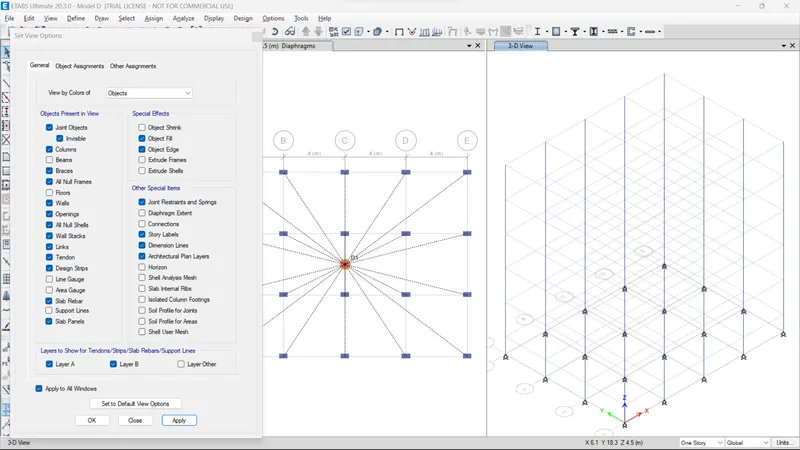
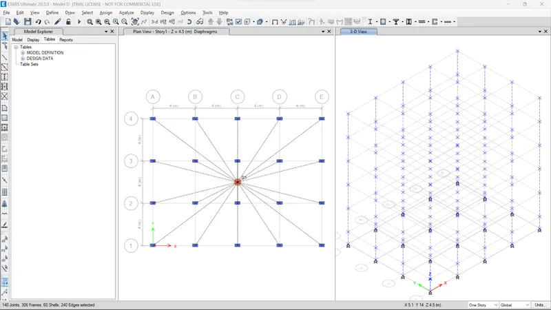
Got assign > Frame > Local Axes> define 0 degree> Press apply
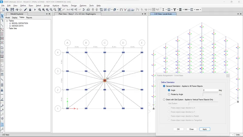
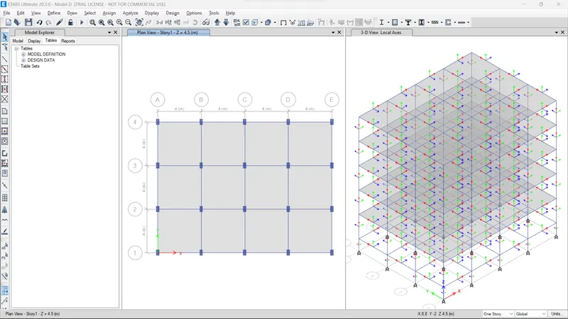
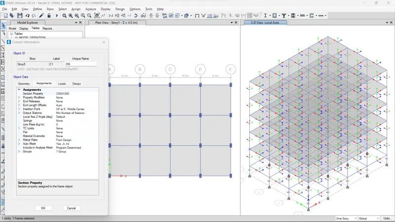
Assign Diaphargram
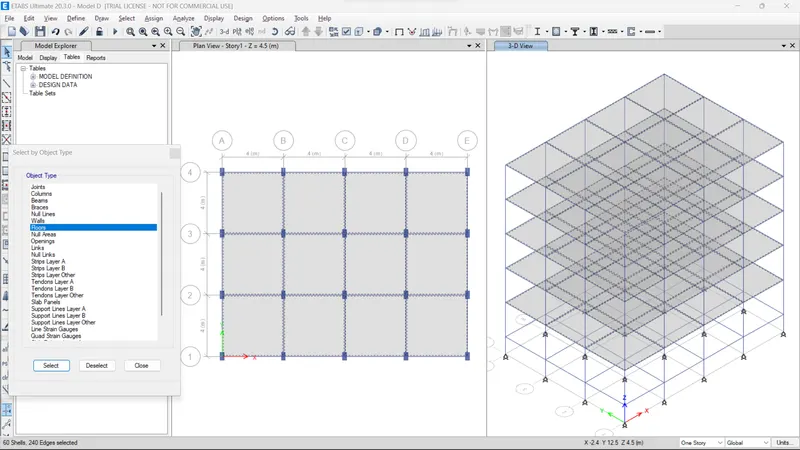
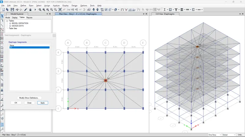
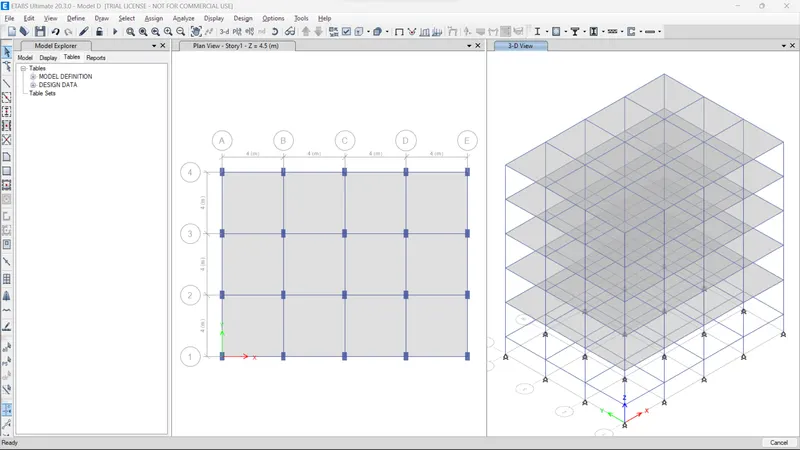
Run Analysis
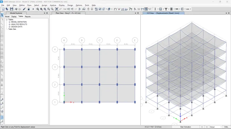
Results of Modal D
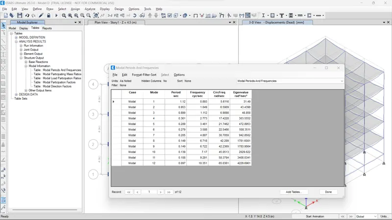
Modal periods and frequencies
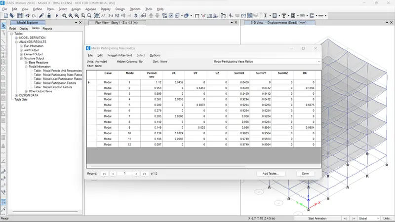
Modal participating mass ratios
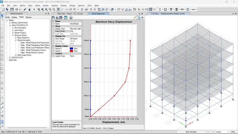
Maximum story dispalcement EQx
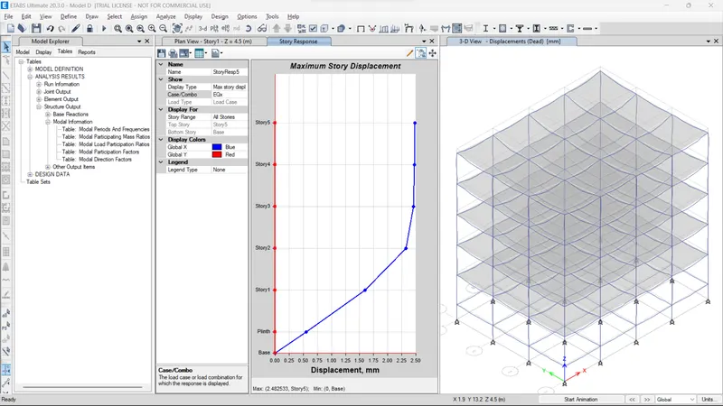
Maximum story dispalcement EQy
MODAL-E
Save Modal D as Modal E (simply make a copy) (Because Grids, Story Height, load cases, And other parameters are similar)
Changes in modal E is S story added and Column size are also change
The upper 5 story is 400x400mm
And Rest of the story is 600X600mm
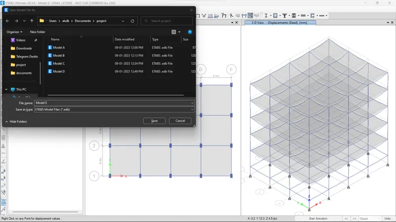
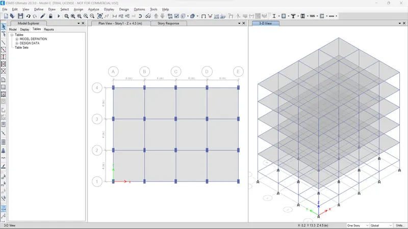
Goto edit > edit grid and story> select Modify story data
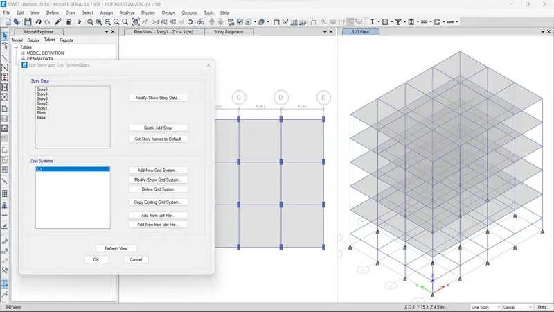
Add 5 stories above the 5th story and similar to story 1
Press ok
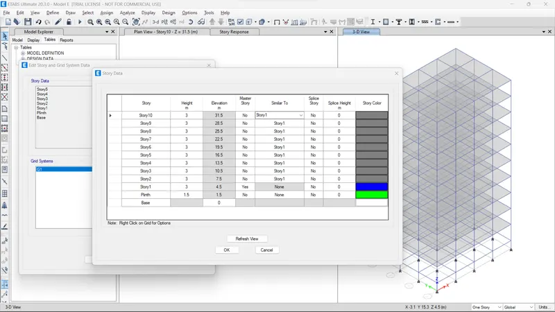
press ok
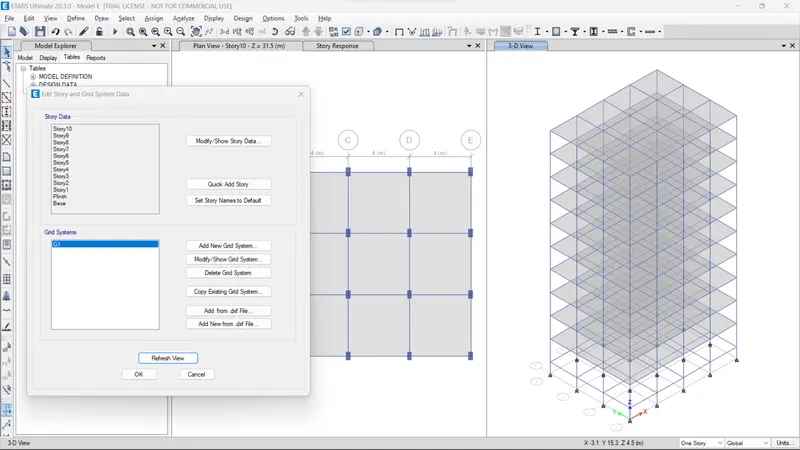
Goto Define > Fram properties> Add new property
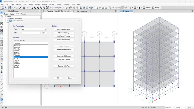
Select rectangular section
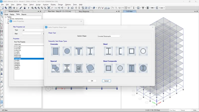
Define parameters
Property name - C600X600
Material- M30
Depth-600mm
Width-600mm
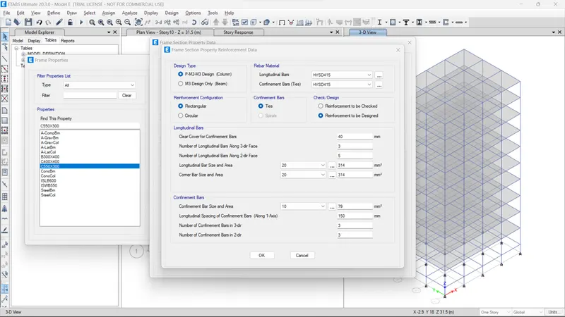
Goto Modify Rebar
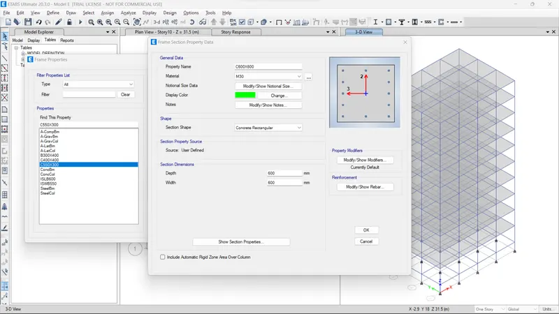
Select design type - Column
Rebar material- Both Longitudinal and ties - HYSD415
Press ok
Press ok
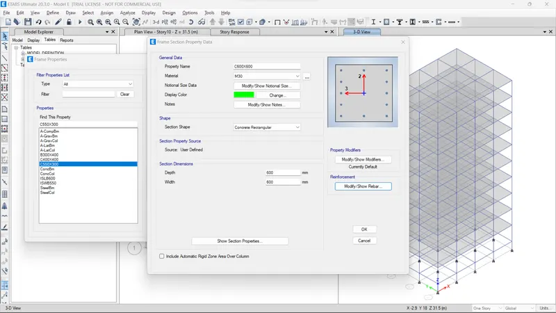
Press ok
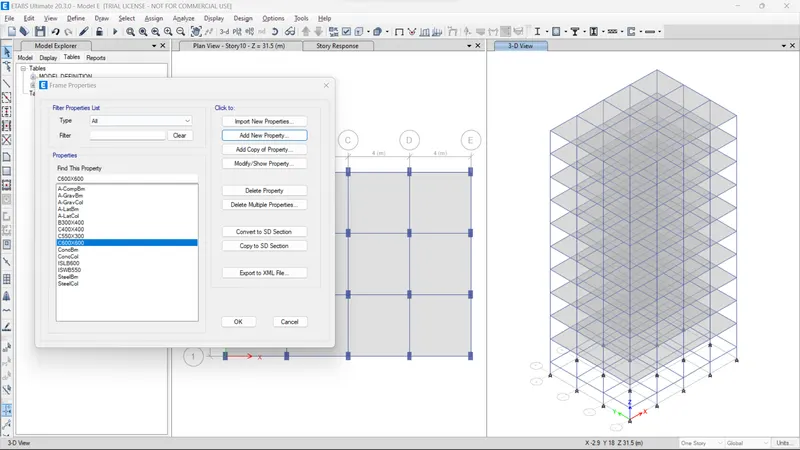
Goto set building view limits in the View toolbar
select Top story- Story 10
Base - Story 6
Press ok
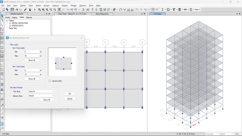
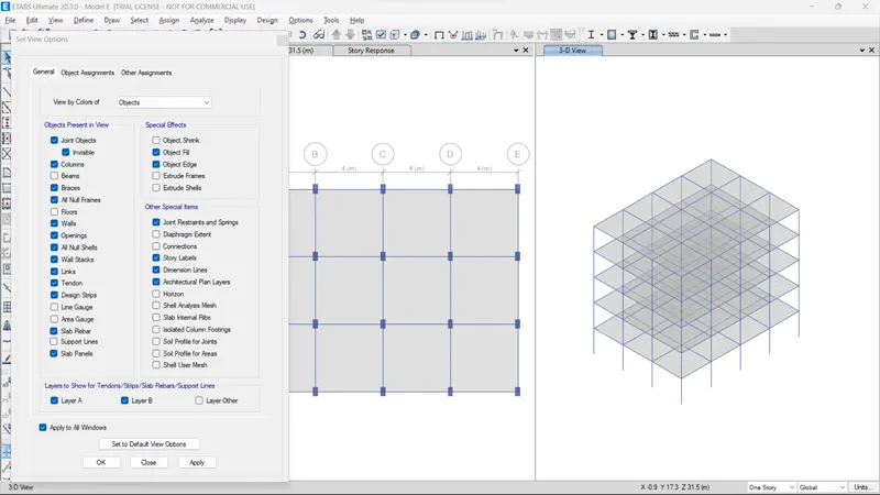
Set view option
Deselect beams and floor
Press Apply
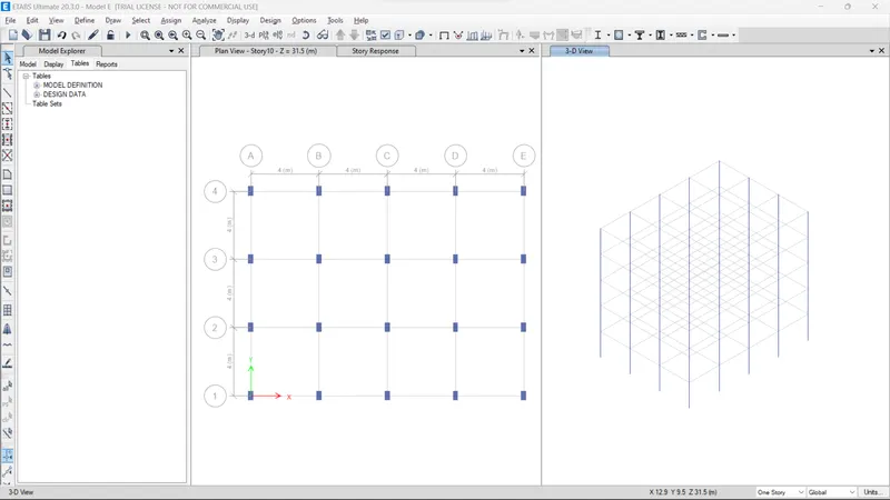
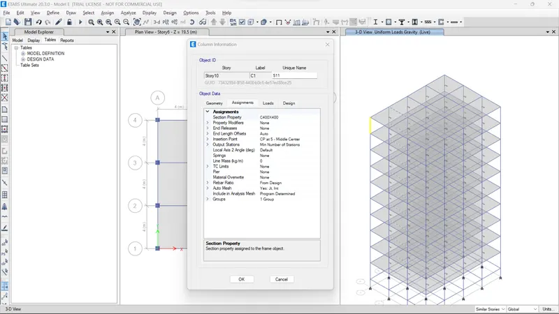
Select all columns visible on the screen
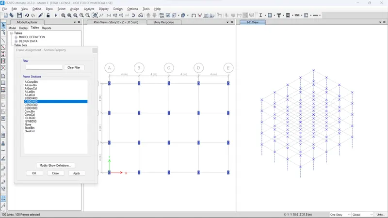
Then Assign column size
Goto Frame. section property
Select C400X400
Press Apply
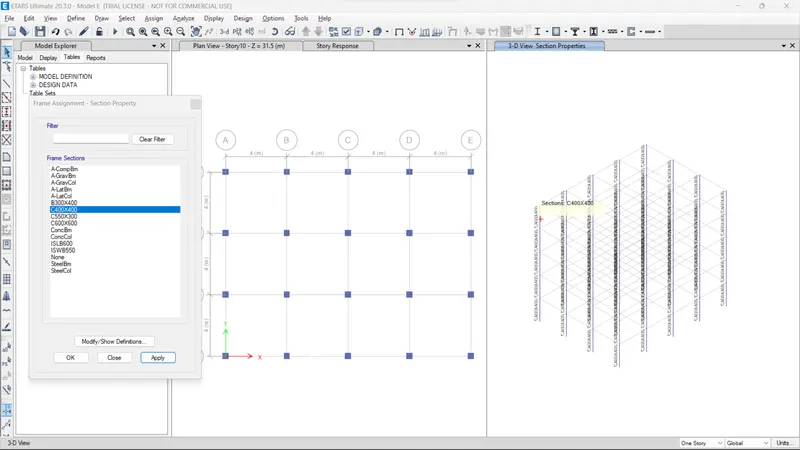
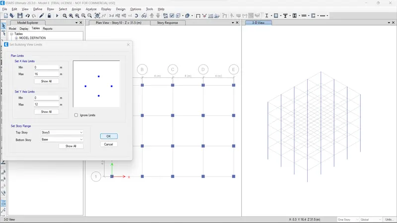
Goto set building view limits
Select Top story- Story 5
Base - Base story
Press ok
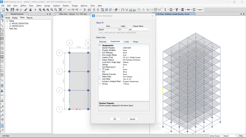
Select all columns visible on the screen
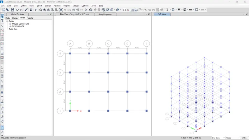
Assign Column size C600X600
Press ok
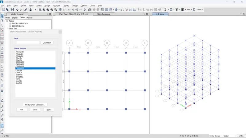
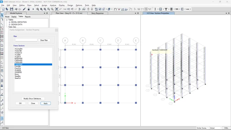
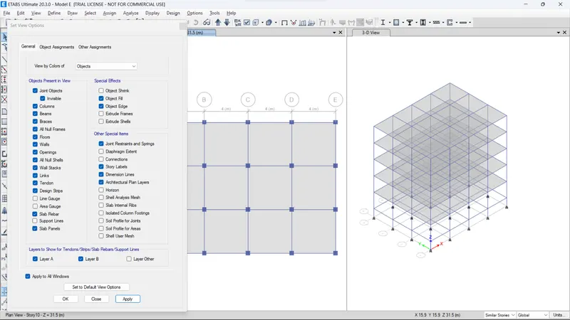
Goto Set view options
Select beam and floor
Press Apply
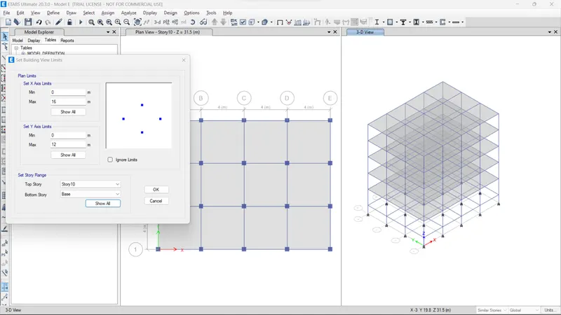
Set building view limits
Press Show all
Press ok
Rest of things same no need to assign load and diaphragm because it ready to assign
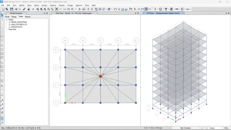
Run Analysis
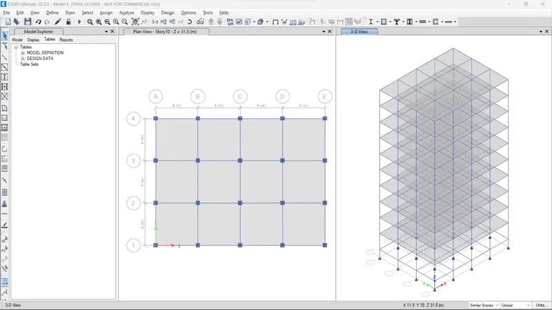
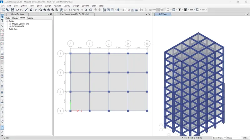
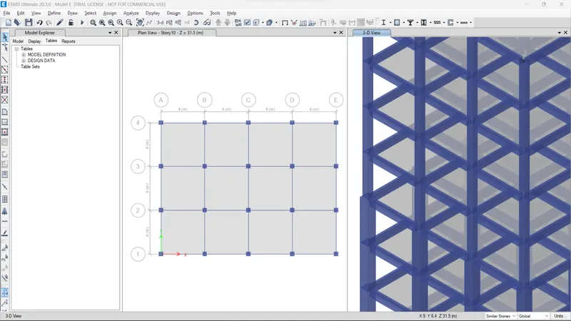
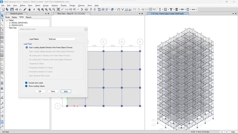
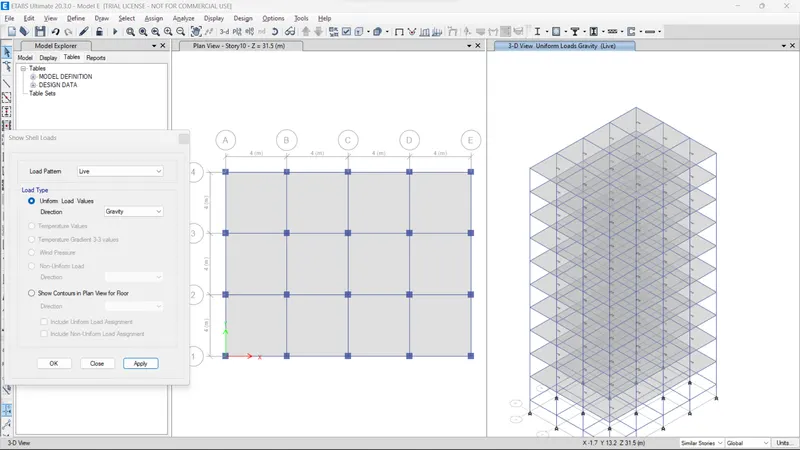
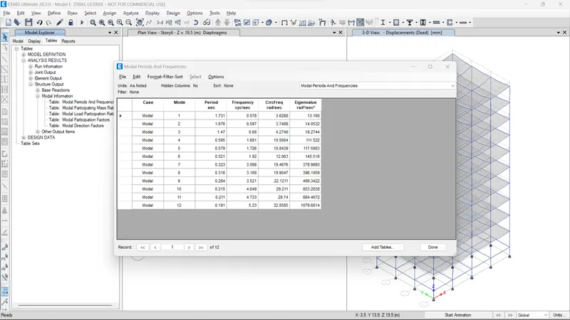
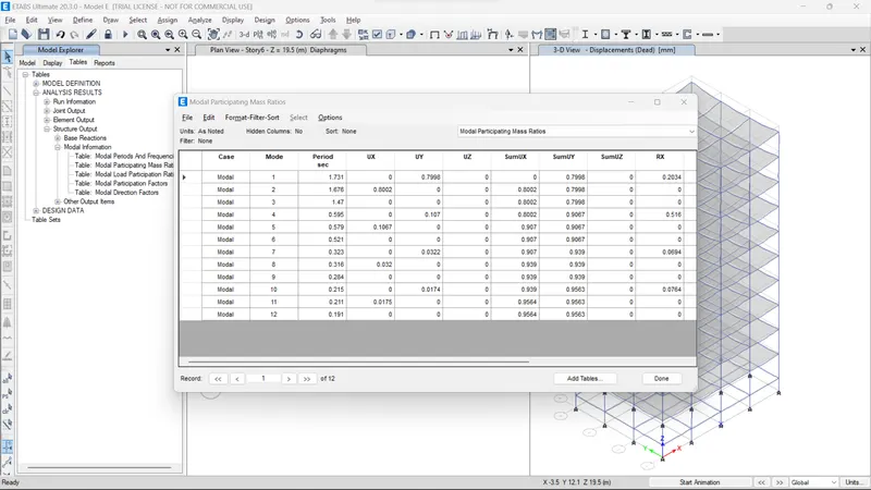
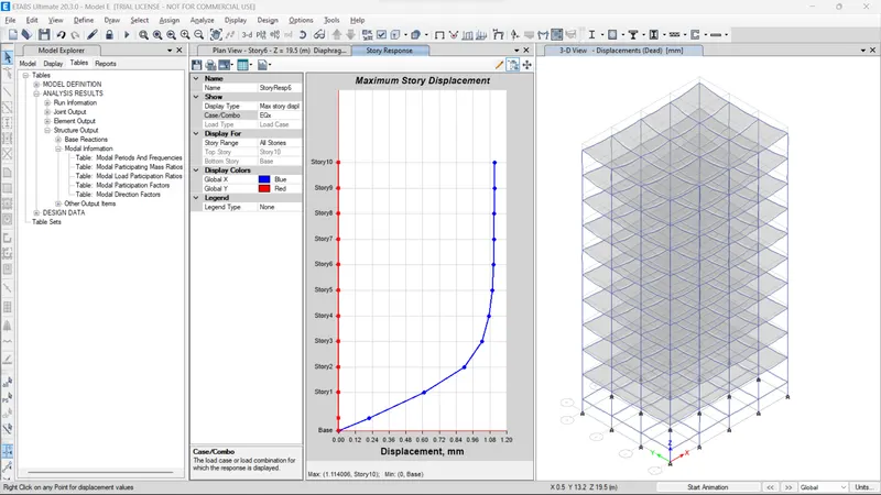
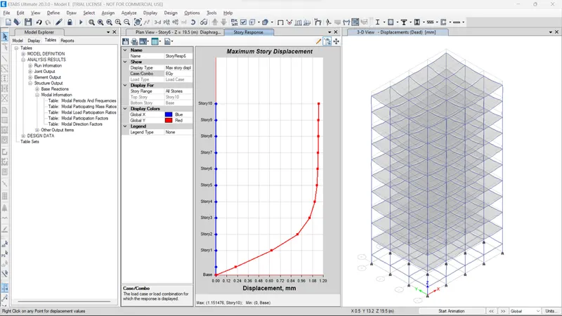
Result of Modal E
Modal Periods and frequencies
The modal participating mass ratio
Maximum story displacement EQx
Maximum story displacement EQy
MODAL-F
Save Modal E as Modal F (simply make a copy) (Because Grids, Story Height, load cases, And other parameters are similar)
Changes in modal E in Column size are also changed
The entire column size is 600X600
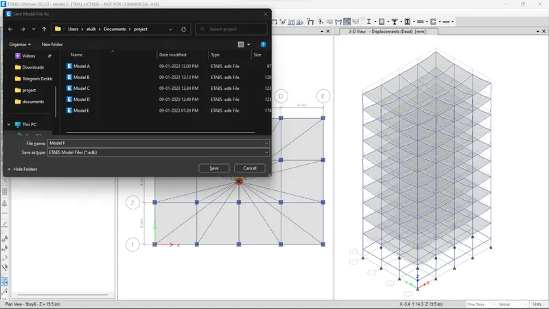
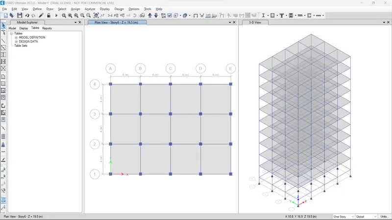
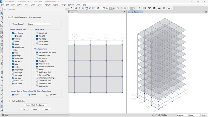
Goto to set view options
Deselect beam and floor
Press Apply
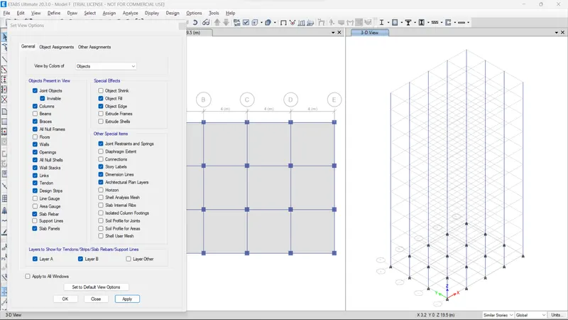
Select entire column
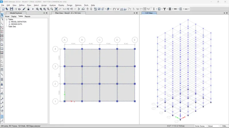
Assign Column Size as C600X600(replacing C400x400)
Press Apply
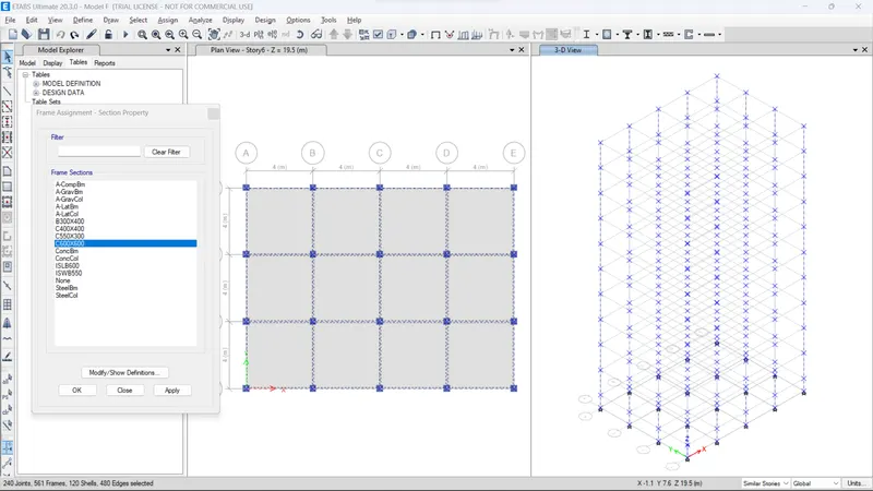
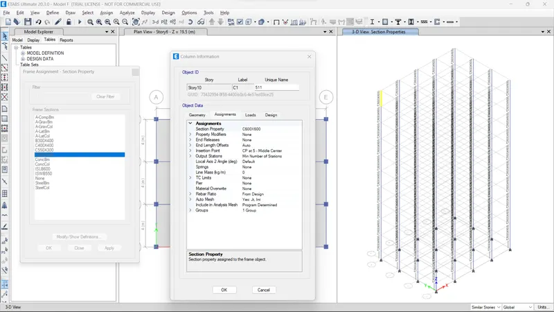
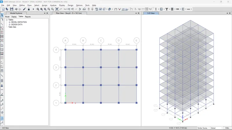
In the previous select beams also doing right (Note: Be careful on selecting the frame and assign members)
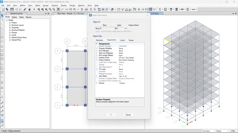
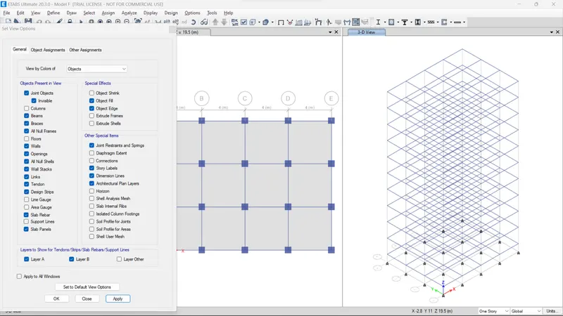
Set view options
Select beams
Press Apply
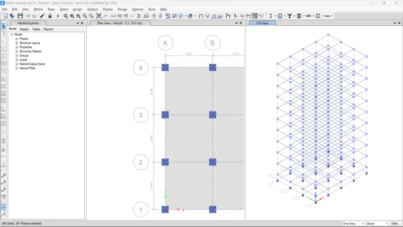
Goto Define frame > Section property
Select B300X400
Press Apply
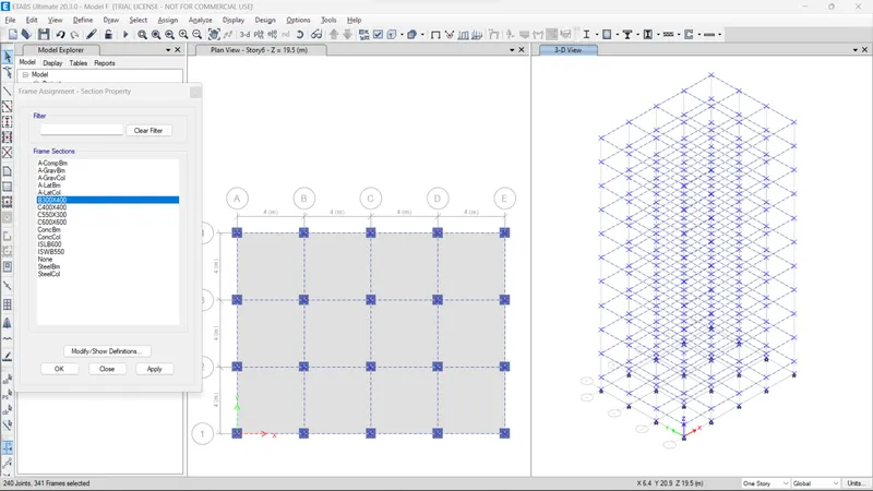
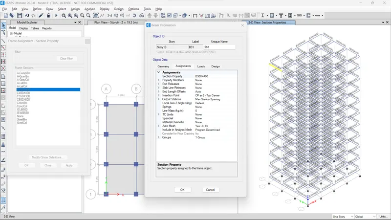
Now everything is applied already no need to apply or assign
Just goto run the Analysis
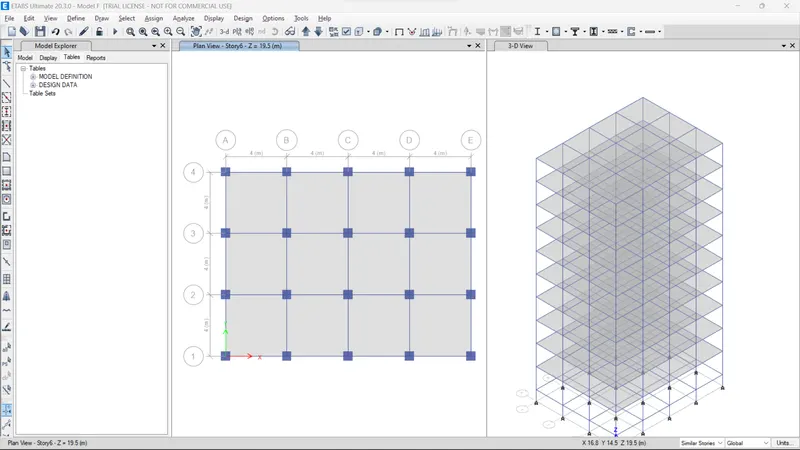
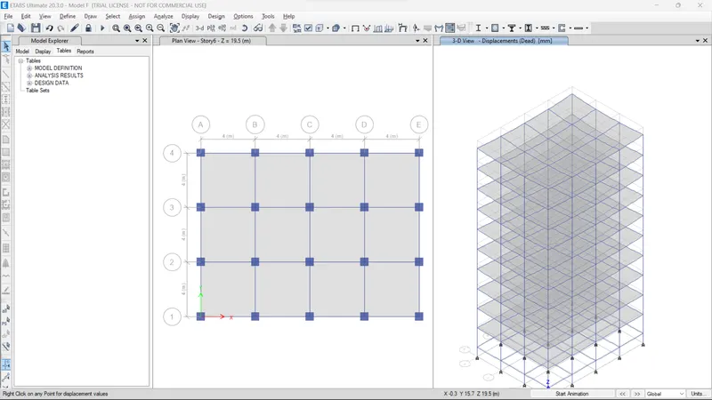
Result of Modal F
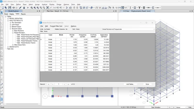
Modal Periods and Frequencies
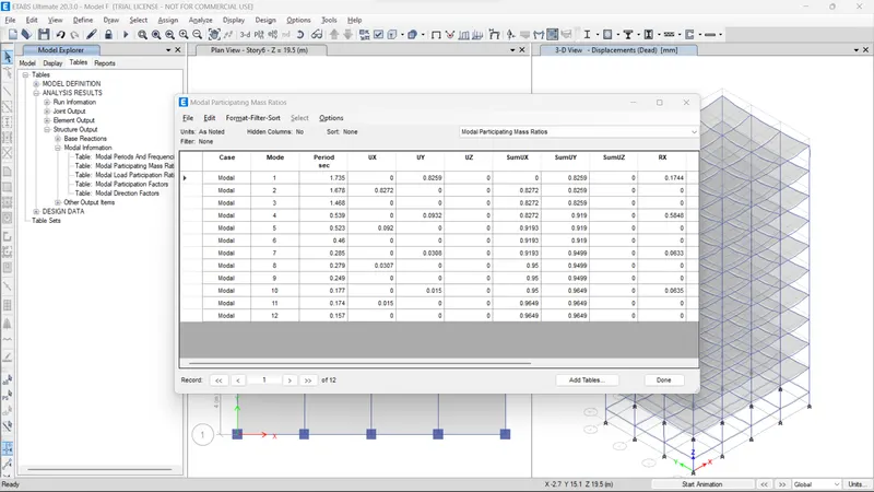
Modal Participating mass ratios
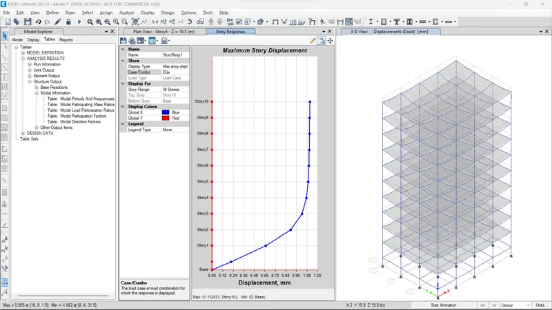
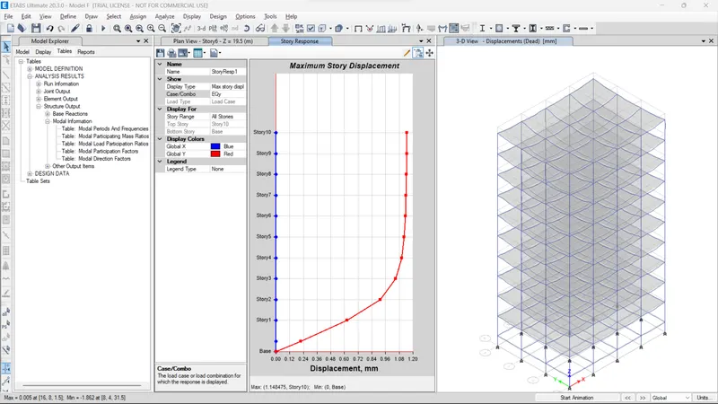
Maximum Story displacement EQx
Maximum Story displacement EQy
MODAL-F
Save Modal E as Modal F (simply make a copy) (Because Grids, Story Height, load cases, And other parameters are similar)
Change as all column size is the same
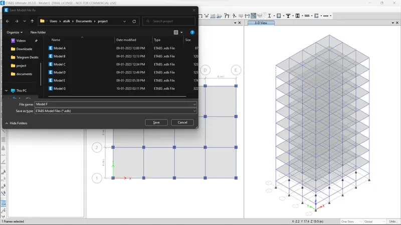
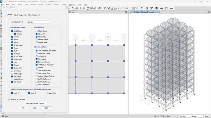
Goto set view options
Deselect Beams and floor
Press Apply
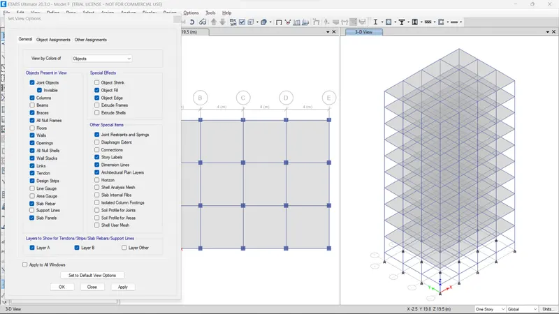
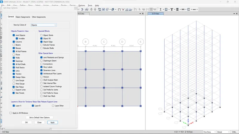
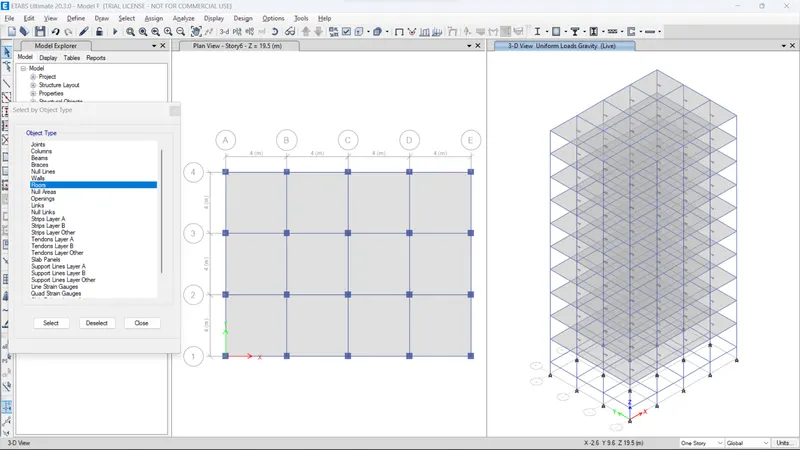
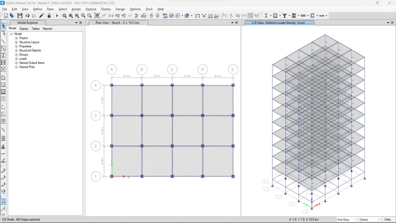
Select all column
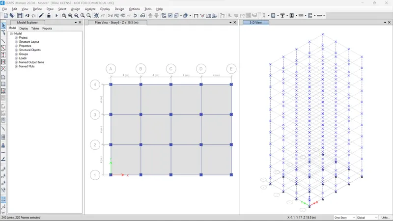
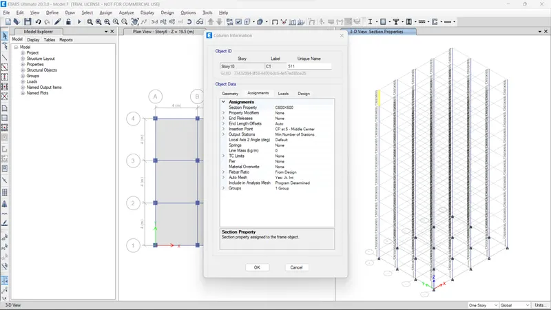
Goto Assign> Frame> section property> select C600X600
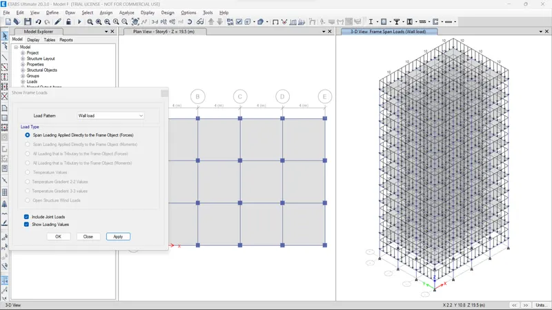
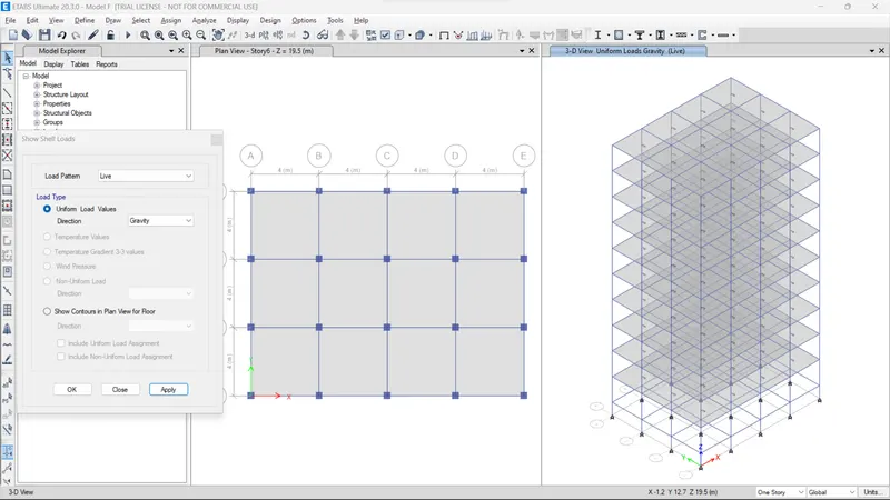
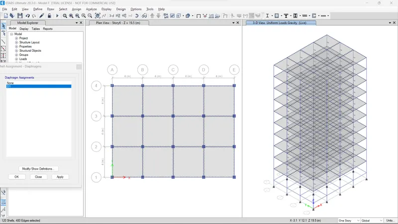
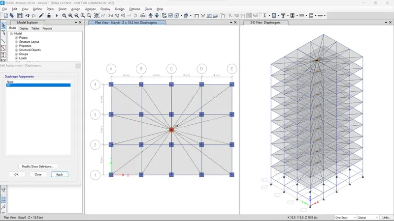
Everything is assigned already
just go Run Analysis
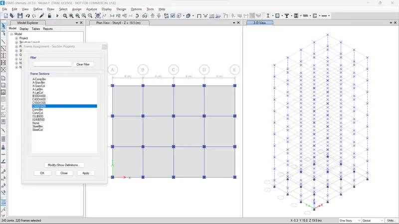
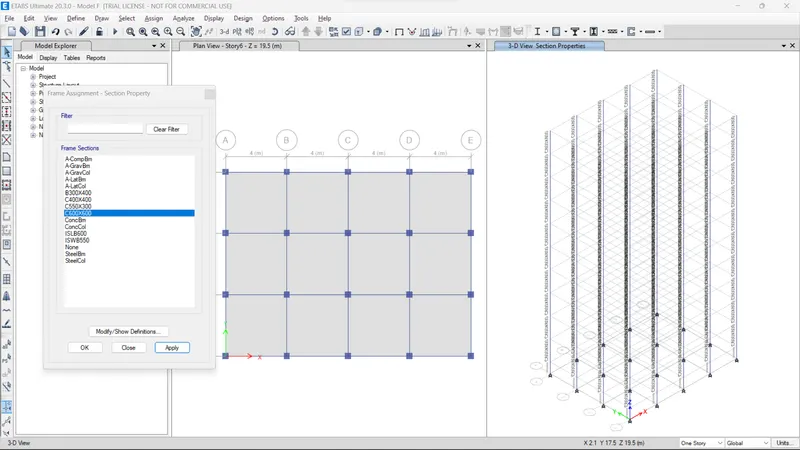
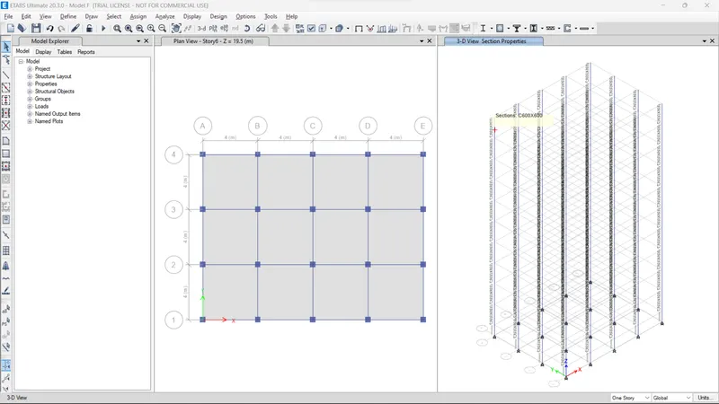
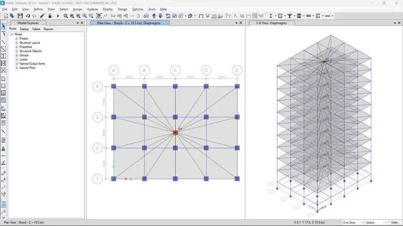
Run analysis
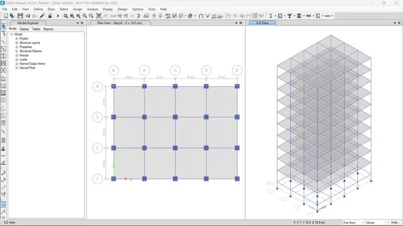
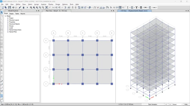
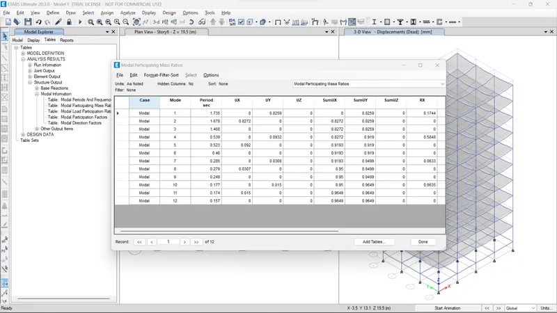
Result of Modal F
Modal periods and frequencies
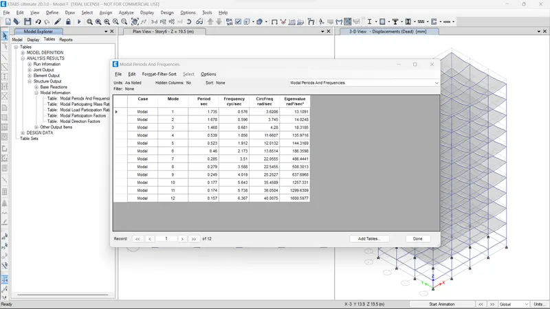
Modal participating mass ratios
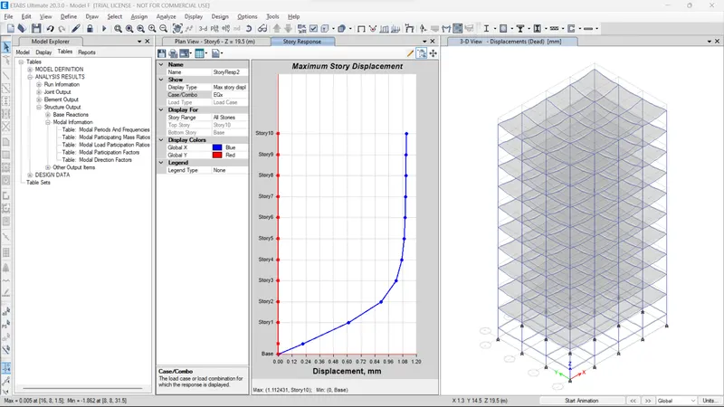
Maximum story displacement along EQx
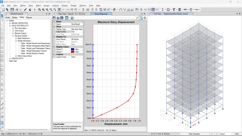
Maximum story displacement along EQx
MODAL-G
Save Modal F as Modal G (simply make a copy) (Because Grids, Story Height, load cases, And other parameters are similar)
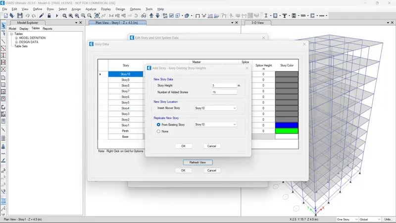
Changes in modal E in Add 15 more stories and Column size are changed
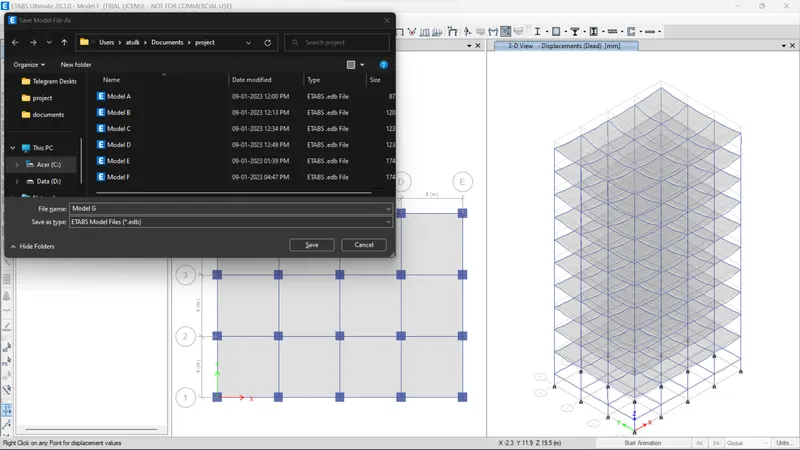
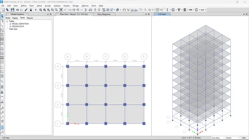
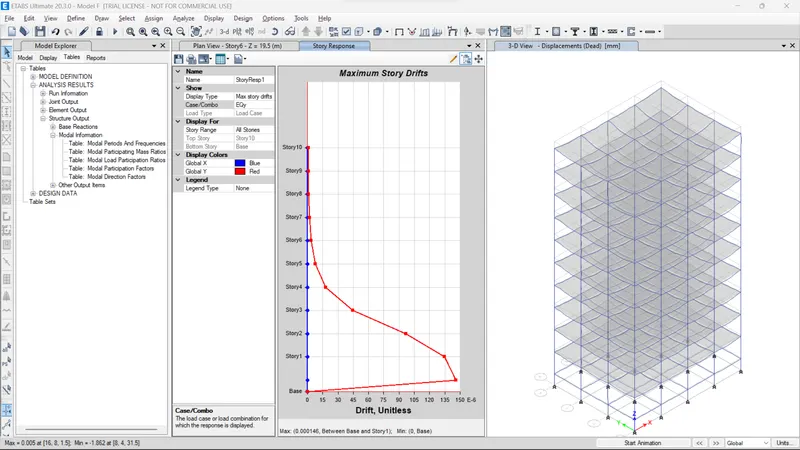
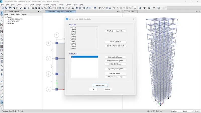
Goto Edit grids and story
Select Modify story data
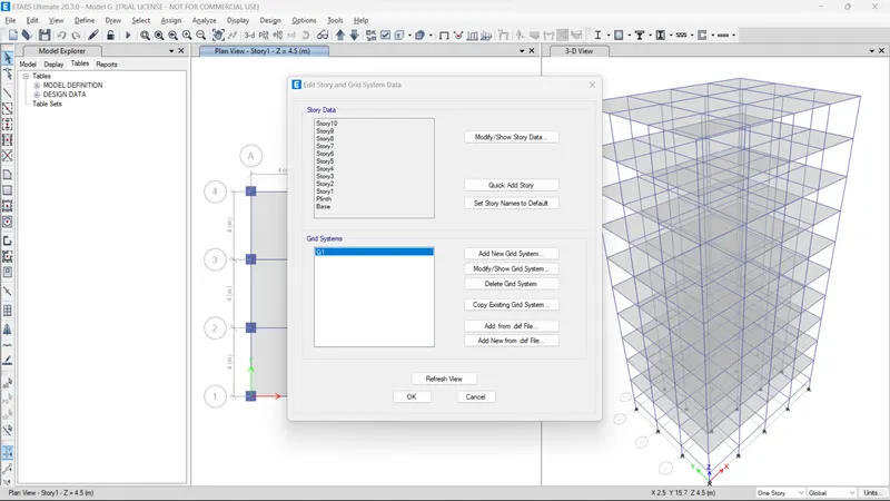
Add 15 Stories above Story 12
All story Similar to story 1
Press ok
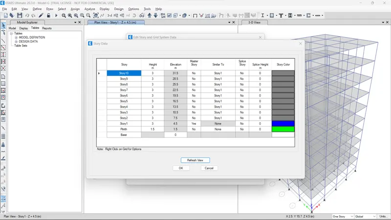
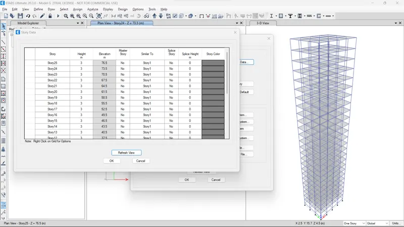
Press ok
Goto set view options
Deselect beam and floors> press apply
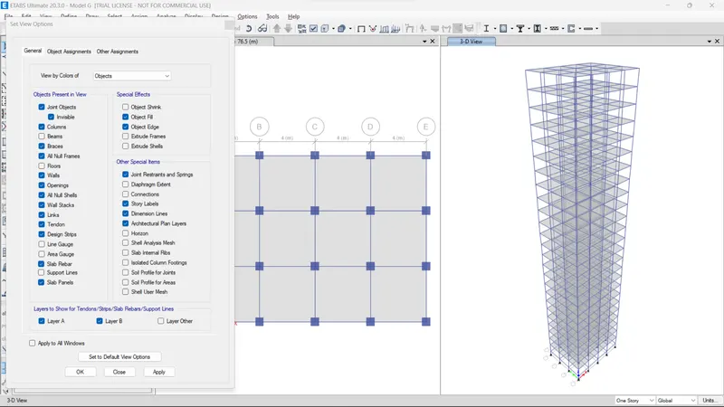
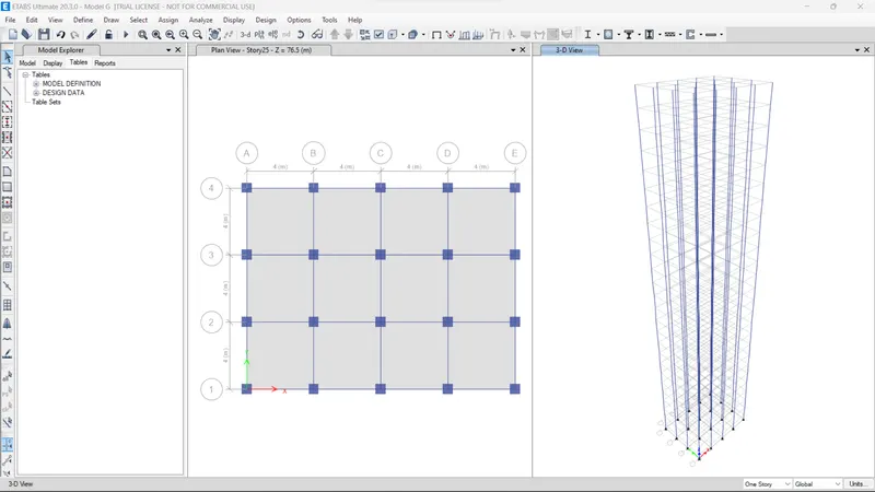
Then goto set building view limits
Top story -story 25
Bottom story- Story-21
press ok
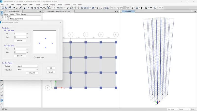
Select all column
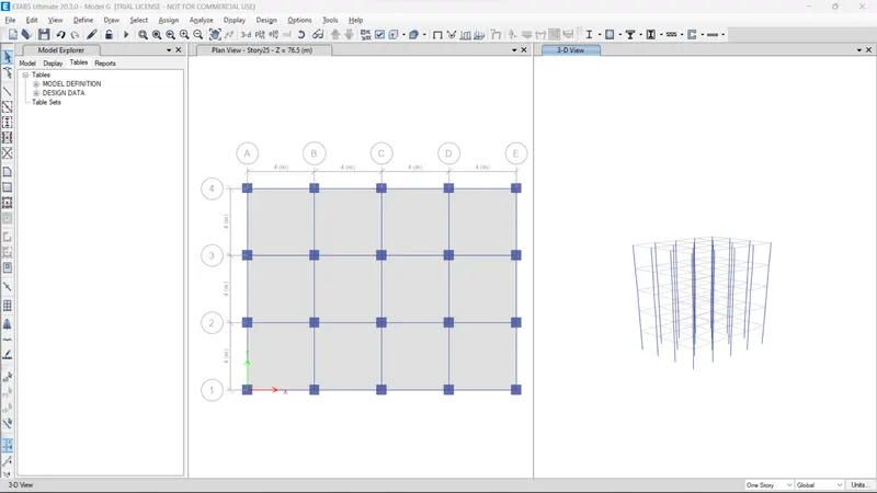
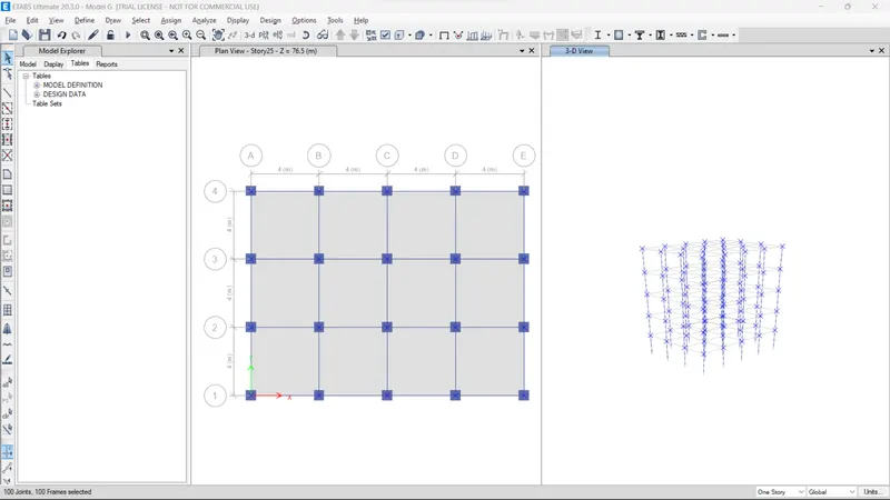
Assign >frame> Section property
Select C400X400
Press Apply
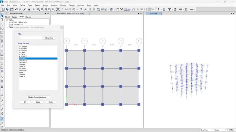
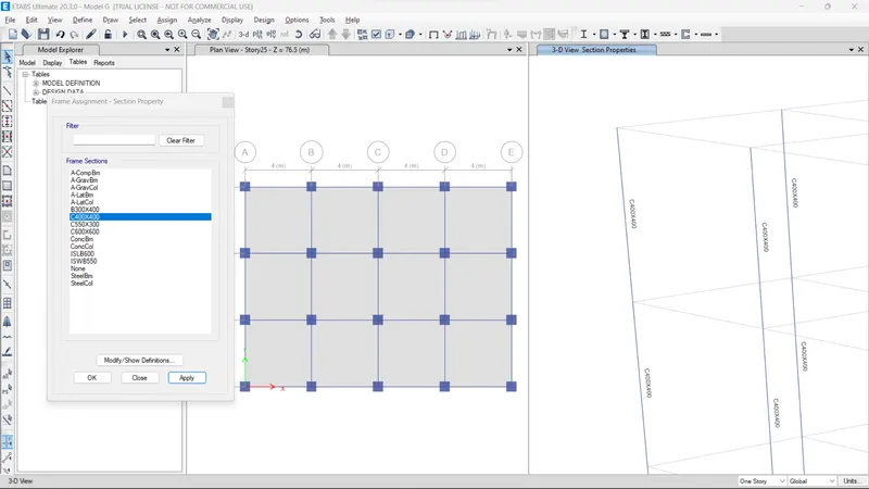
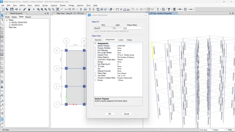
Again goto set building view limits
Top Story - Story 20
Bottom story - Story 11
Press ok
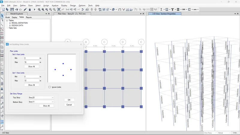
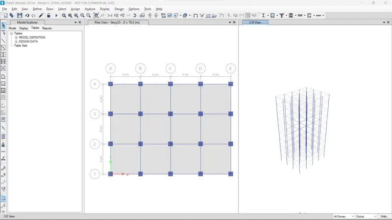
Select all columns visible on the screen
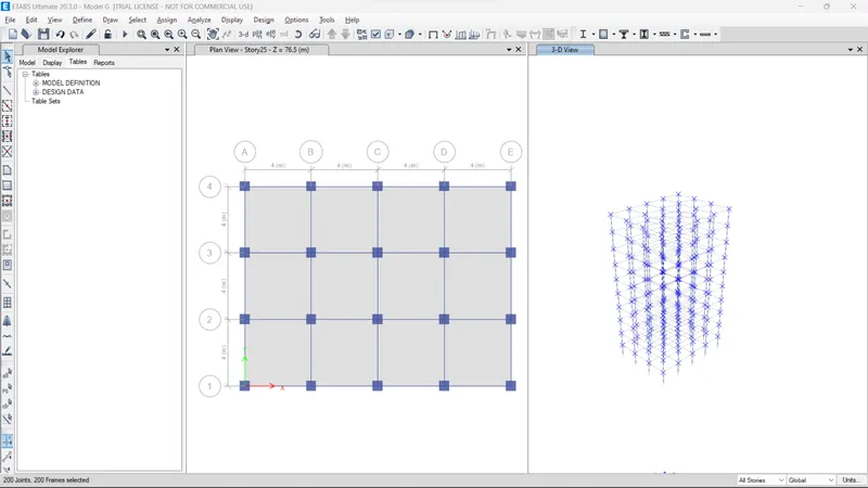
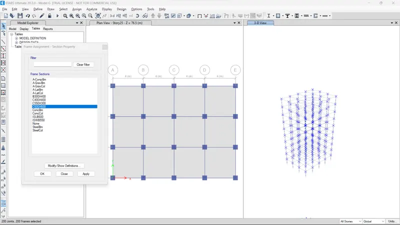
Assign C600X600 to select the column
Press Apply
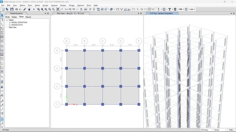
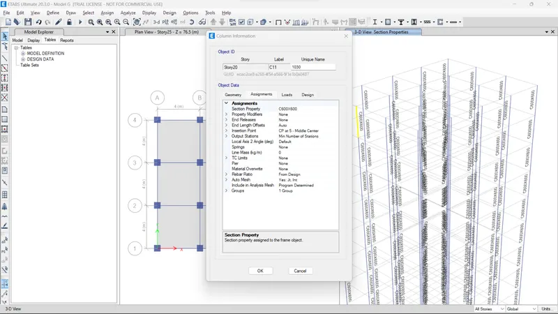
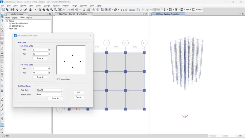
Again goto set building view limits
Top Story - Story 10
Bottom story - Base
Press ok
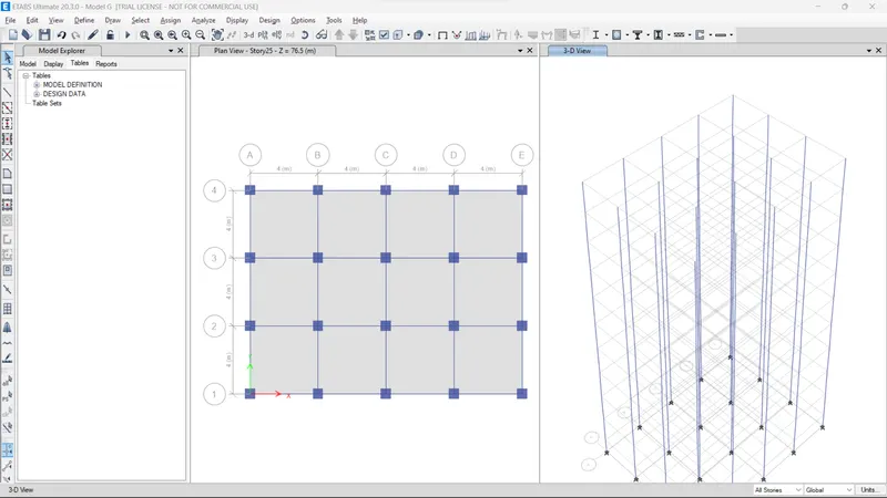
Goto Define >Frame > Add new property
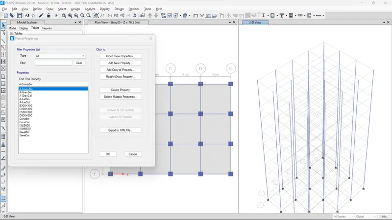
Select rectangular section
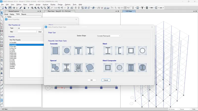
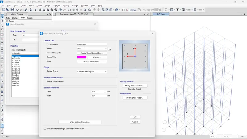
Define Parameters
Property name- C800X800
Material -M30
Depth-800mm
Width-800mm
then Goto Modify rebar
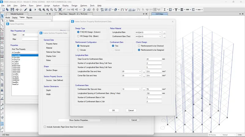
Select Design type- column
Rebar material-both longitudinal and ties bars- HYSD415
Press ok
Press ok
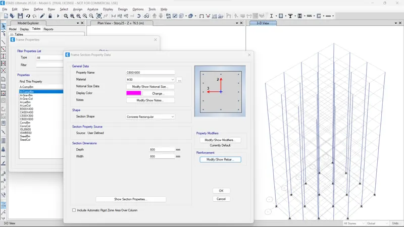
Press ok
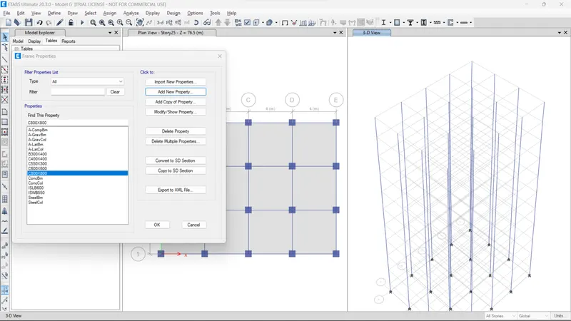
Select all columns visible on the screen
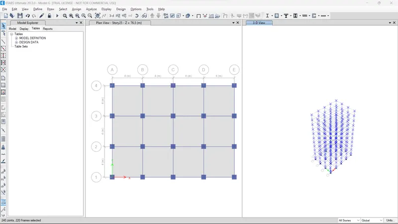
Goto Assign >Frame> Select C800x800> Press apply
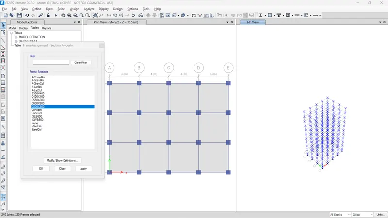
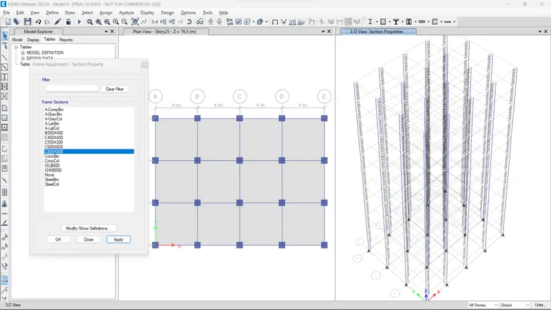
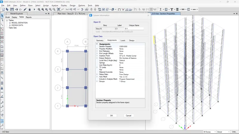
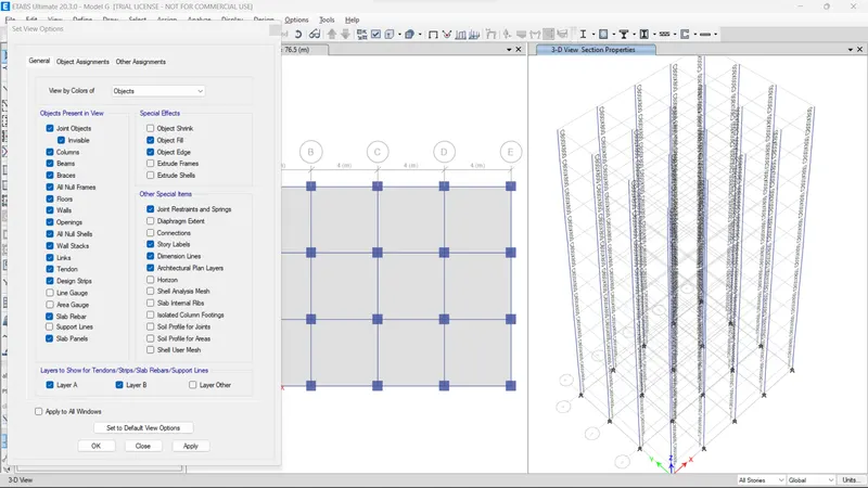
Goto set view options
Select beam and floor
Press Apply
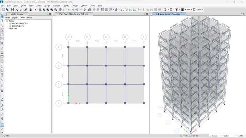
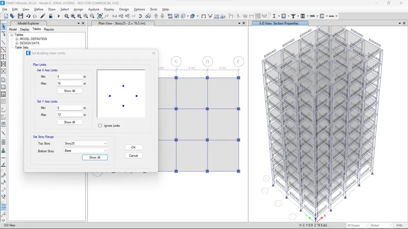
Goto to set building view limits
select show all
Press ok
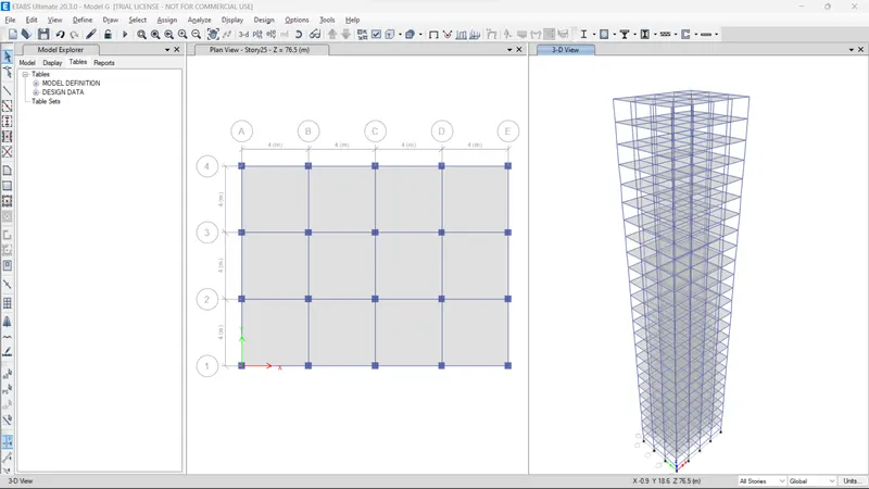
Everything is Assign Live and wall load and Diaphragms are already
Just go to Run Analysis
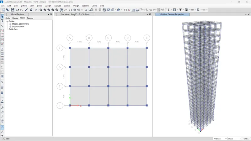
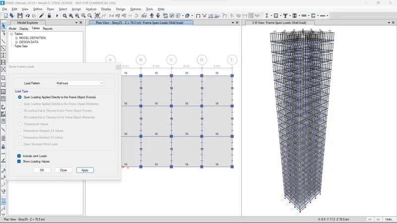
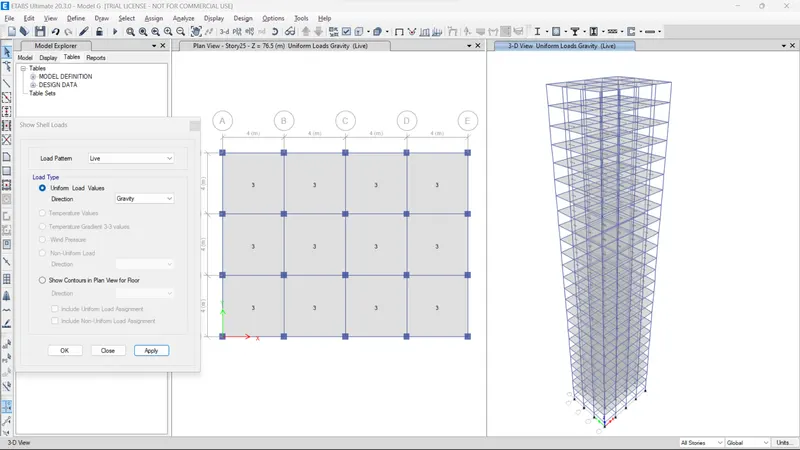
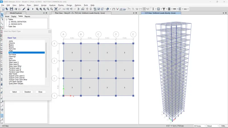

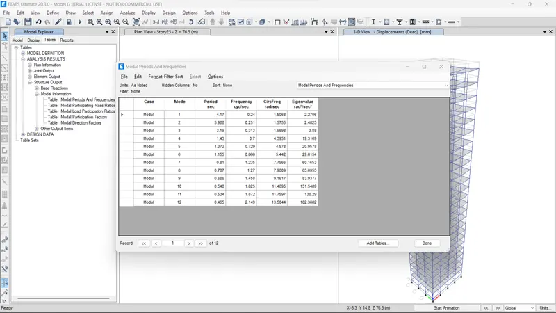
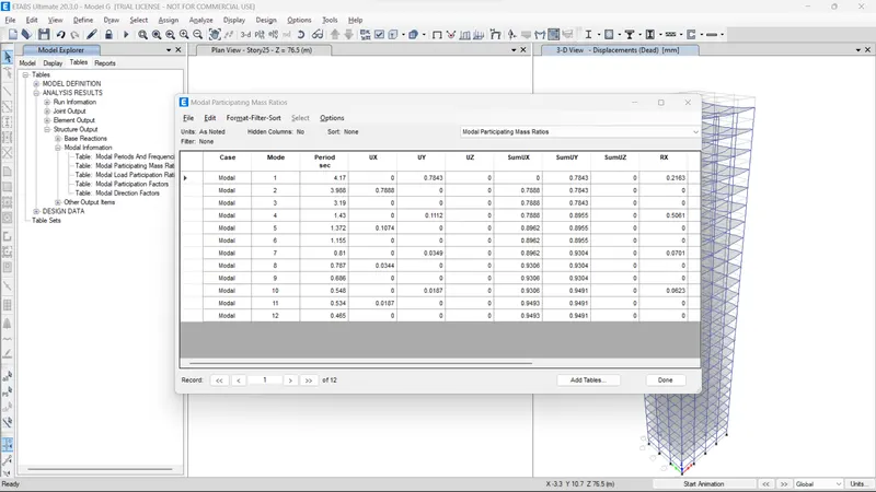
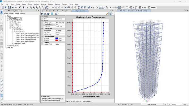
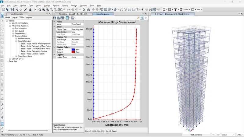
Result of modal G
Modal periods and frequencies
Modal participating mass ratios
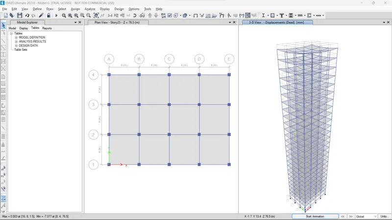
Maximum story dispalcement EQx
Maximum story dispalcement EQY
MODAL-H
Save Modal G as Modal H (simply make a copy) (Because Grids, Story Height, load cases, And other parameters are similar)
Changes in modal H all columns are in the same size C800X800
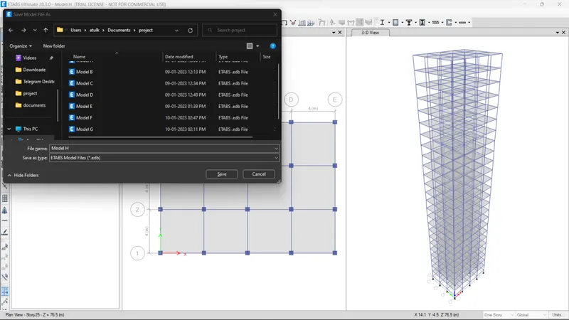
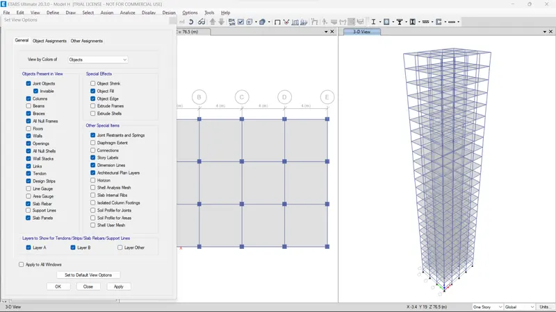
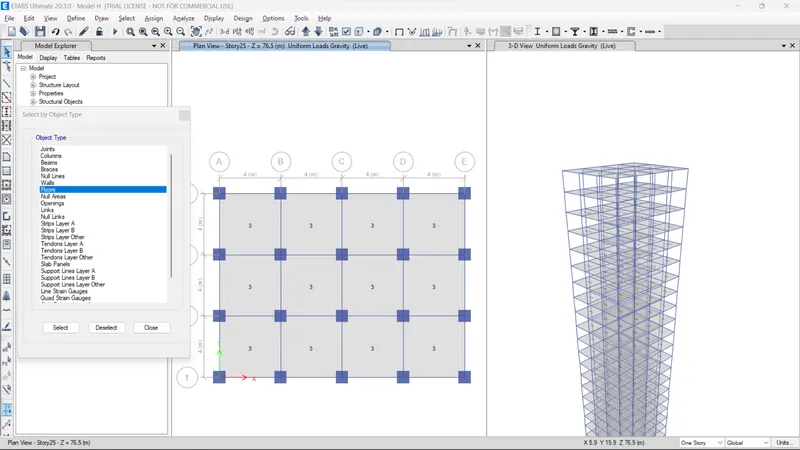
Goto set view option
select beam and floor
press apply
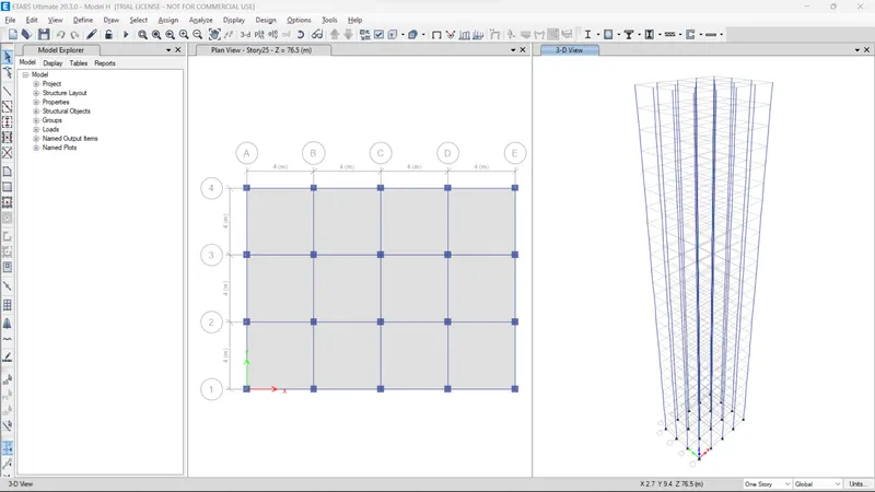
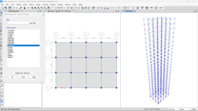
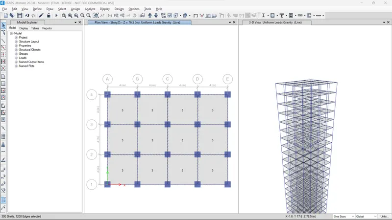
Select all column
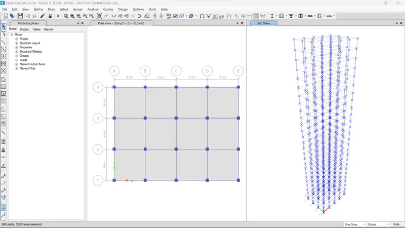
Goto Assign > frame > section property
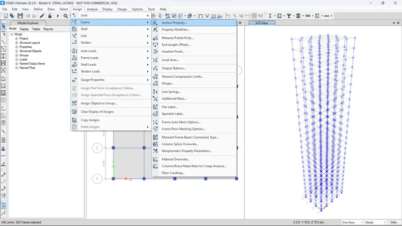
Select C800X800
press ok
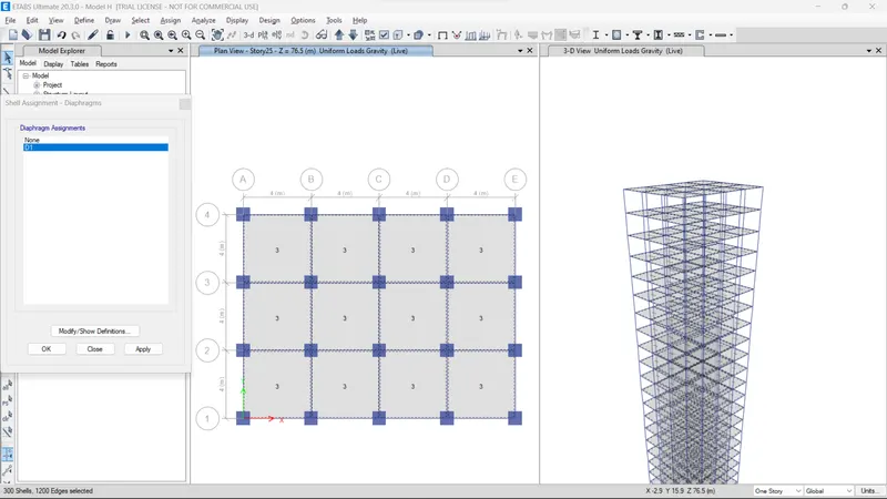
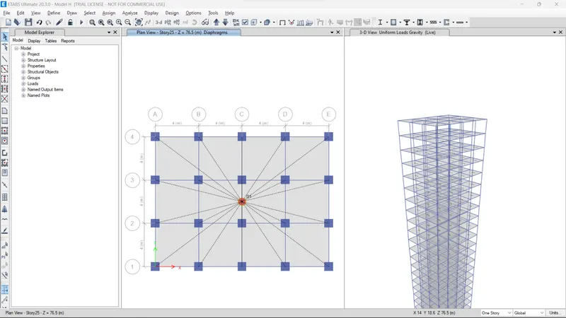
Everything is assigned already like live and dead load, diaphragms
Just Goto Run Analysis
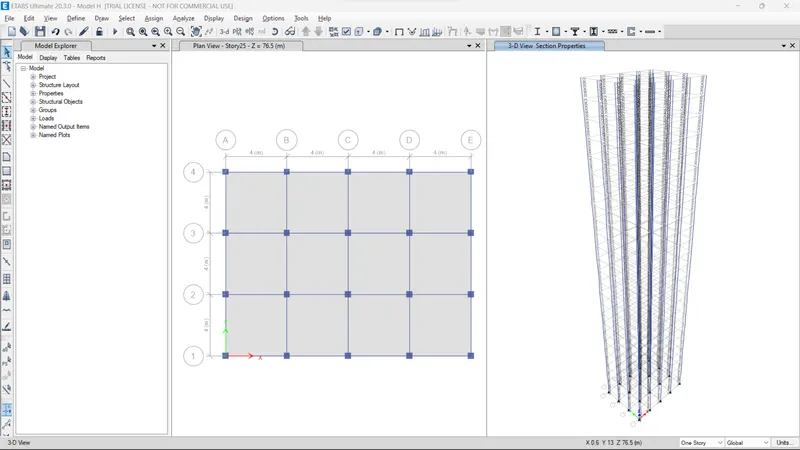
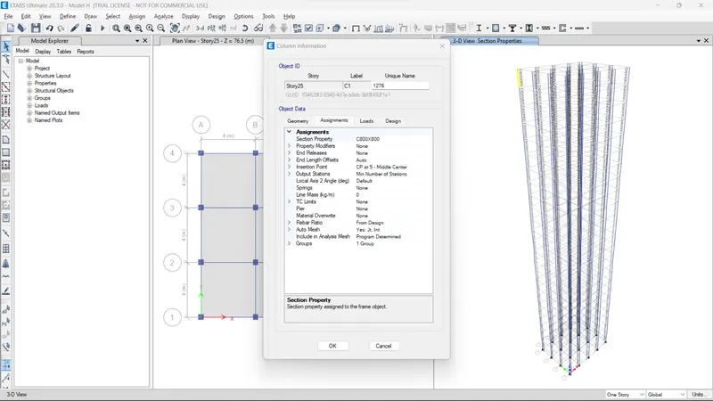
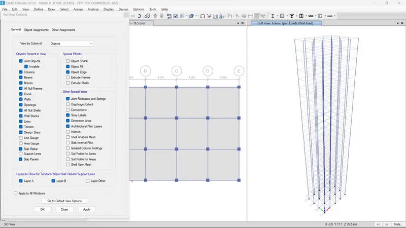
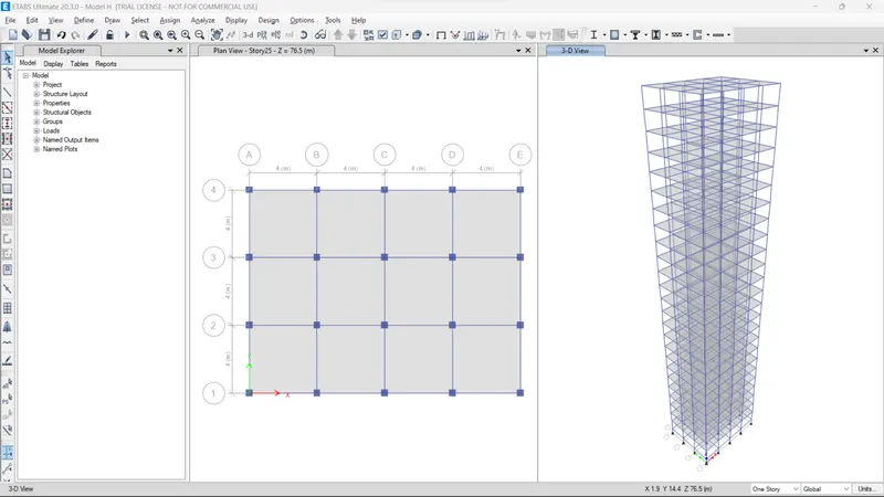
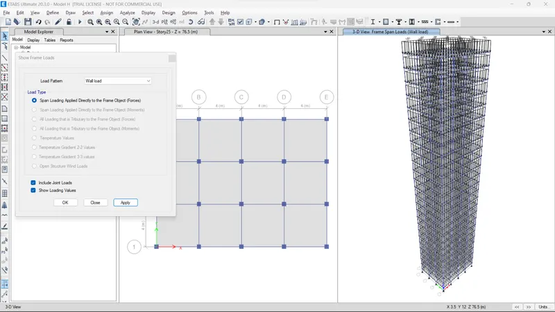
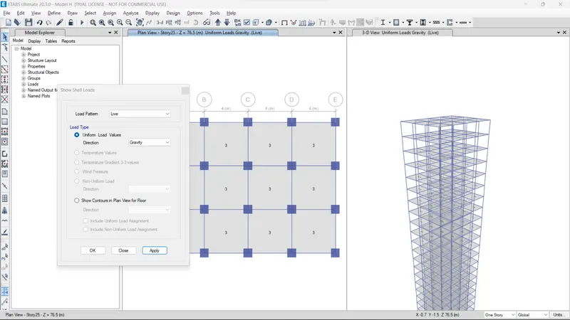
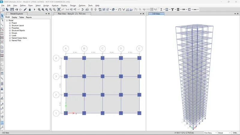
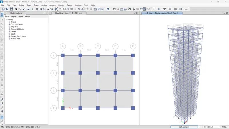
Result of Modal H
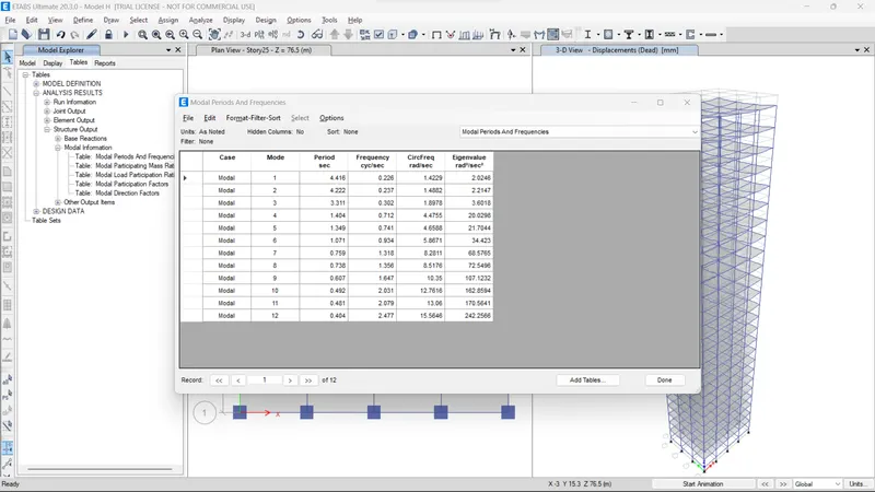
Modal periods and frequencies
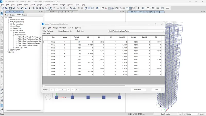
Modal Participating mass ratios
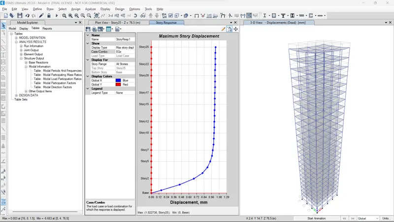
Maximum story displacement EQx
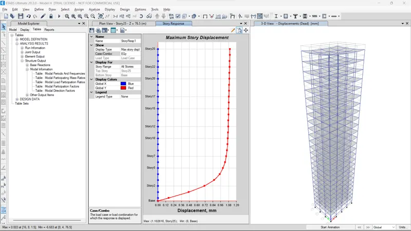
Maximum story displacement EQy
MODAL-J
Save Modal H as Modal J (simply make a copy) (Because Grids, Story Height, load cases, And other parameters are similar)
Changes in modal J Impose load are increased by 10% of the previous live load
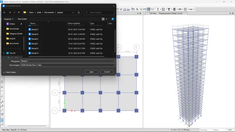
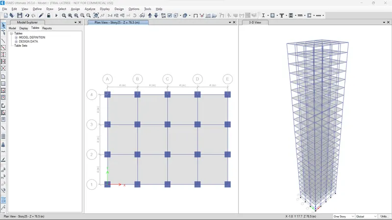
As we see on Floor 3kn/m2 live loads are applied
here we replace that load in 3.3kn/m2
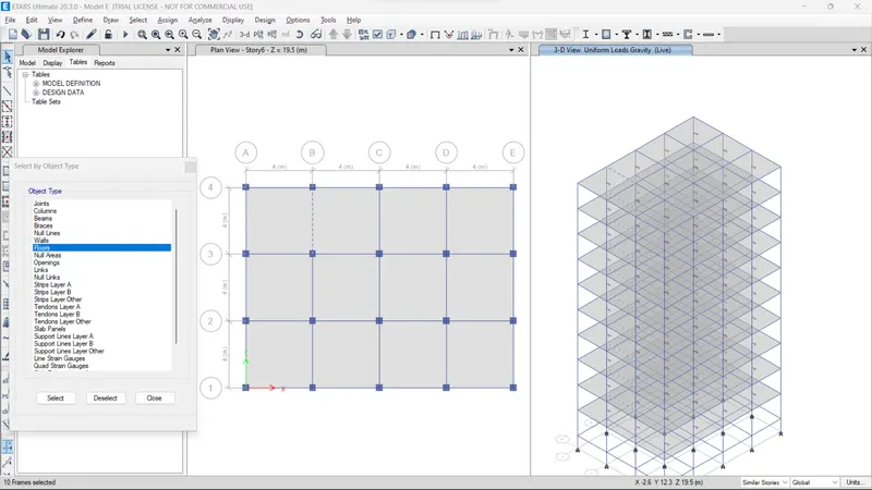
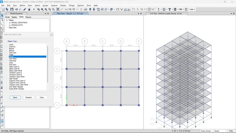
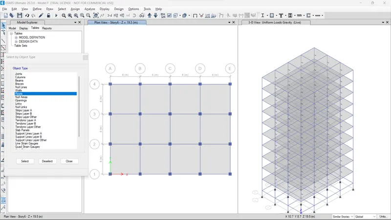
Goto select by object type> Select Floors
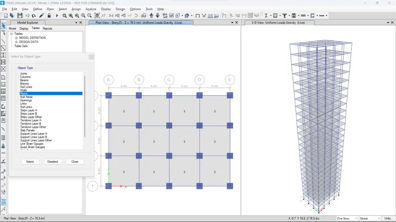
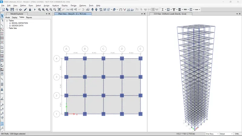
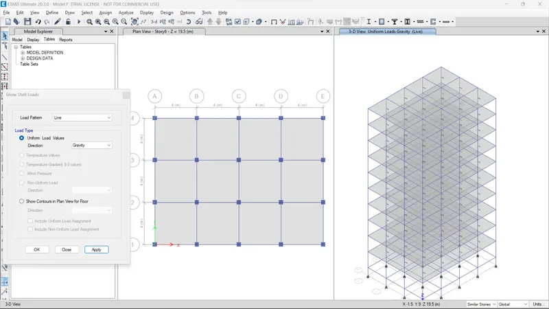
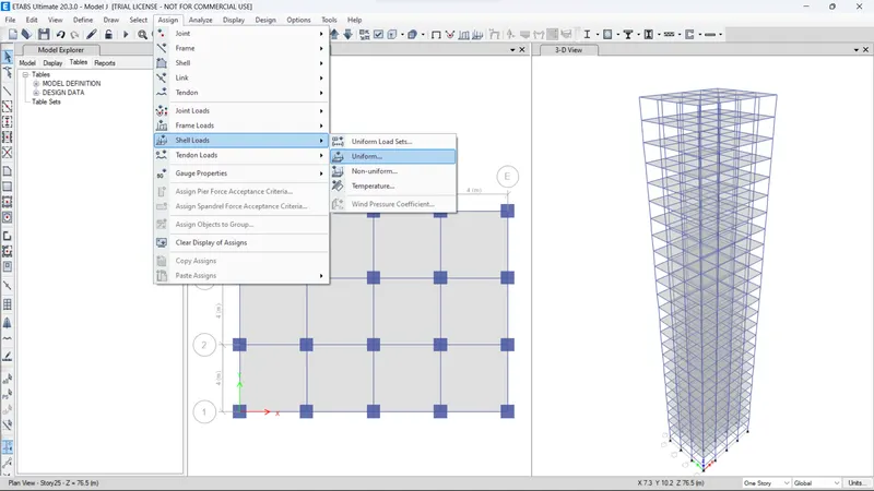
Goto Assign > shell loads> uniform
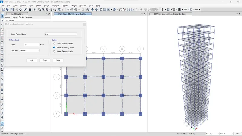
Define load 3.3kn/m2
Select replace existing load
Press Apply
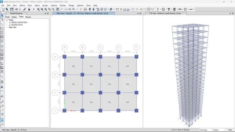
Everything is assigned already Like the wall load and Diaphragms, supports
Just go to Run Analysis
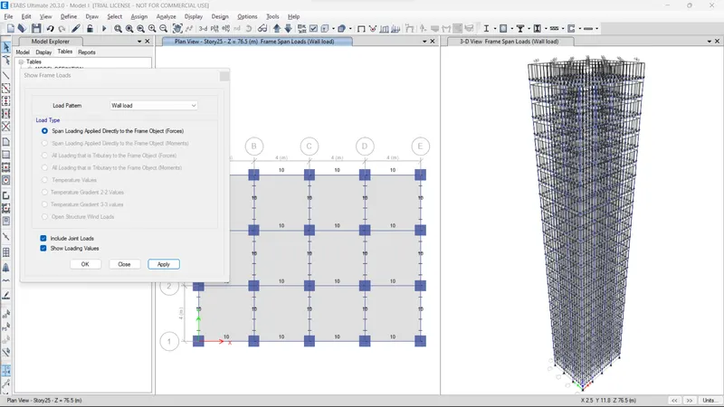
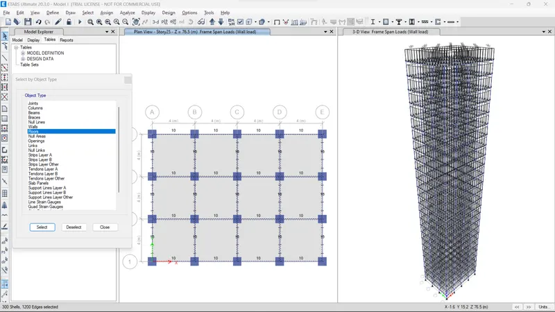
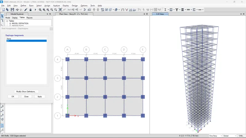
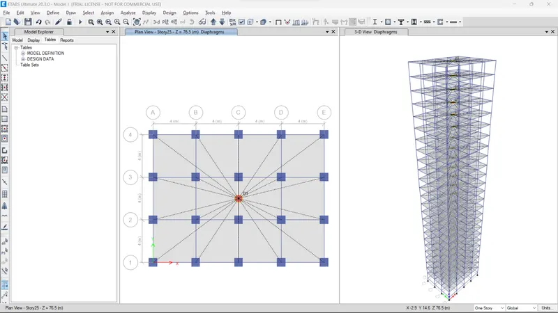
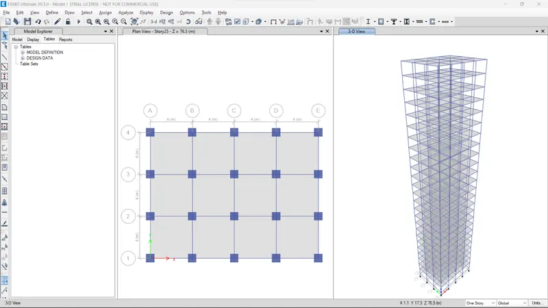
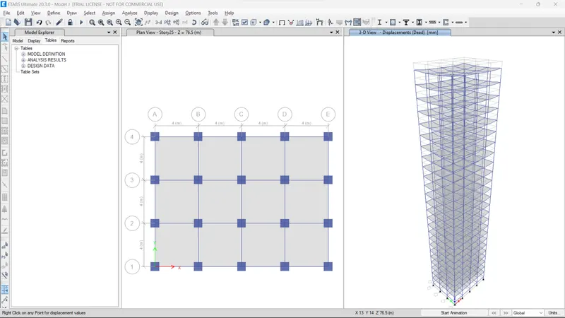
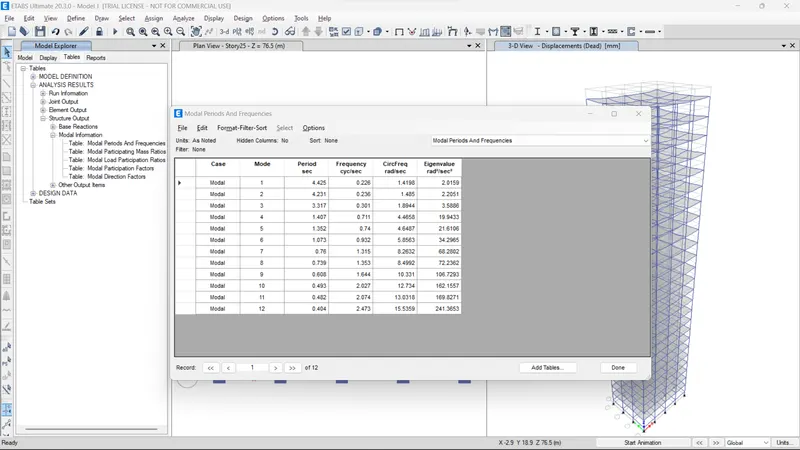
Result of Modal J
Modal periods and frequencies
The modal participating mass ratio
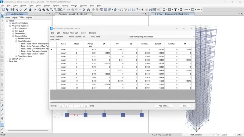
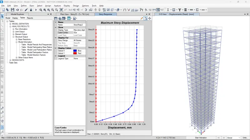
Maximum story displacement EQx
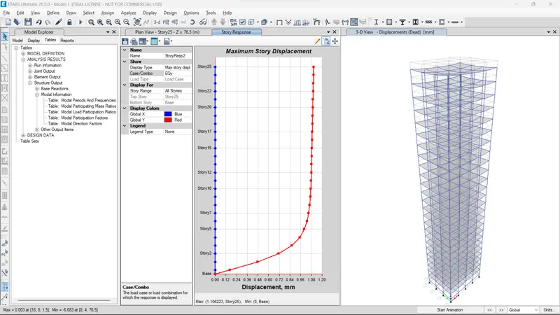
Maximum story displacement EQy
MODAL-K
Save Modal J as Modal K (simply make a copy) (Because Grids, Story Height, load cases, And other parameters are similar)
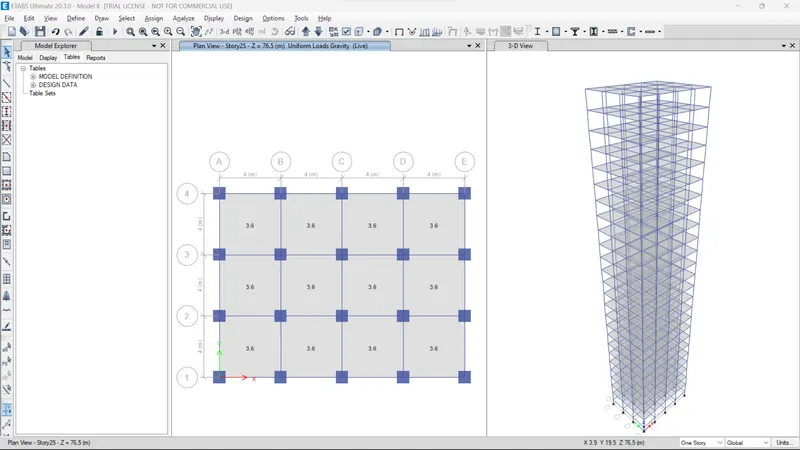
Changes in modal J Impose load are increased by 20% of the previous live load
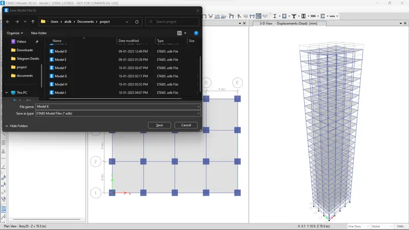
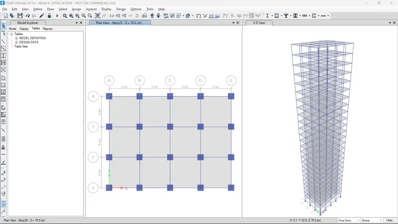
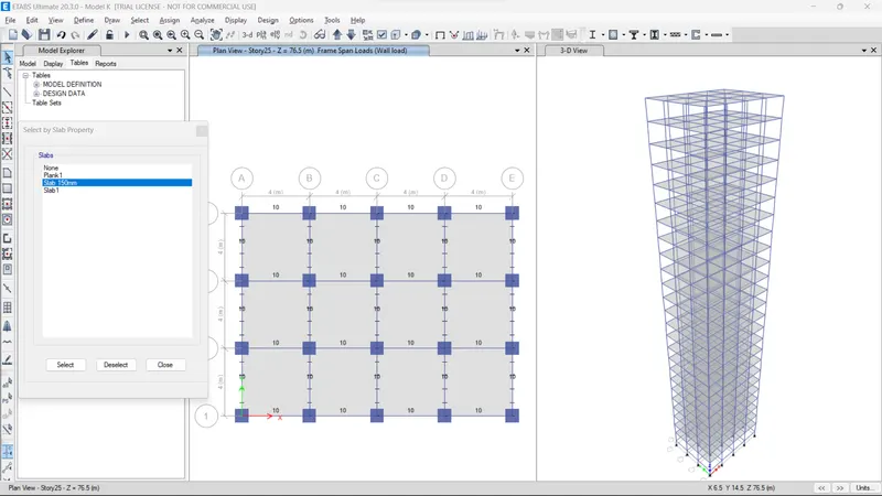
Goto Select by slab property
select slab 150mm
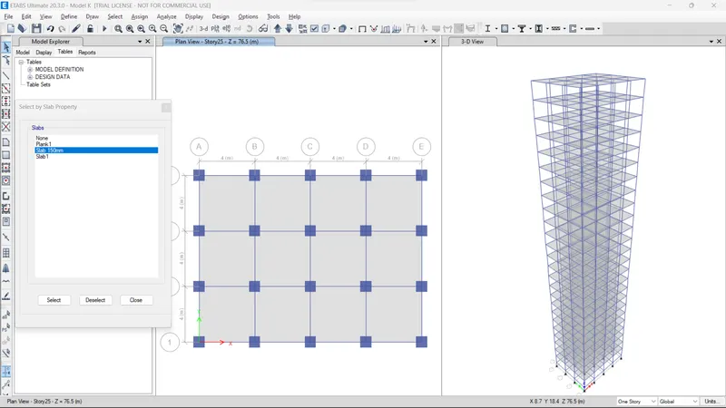
Then go to assign uniform load -3.3 to 3.6kn/m2
Select Replace Existing loads
Press Apply
Everything is Already assigned like wall load, Diaphragms, Support
Just Goto Run Analysis
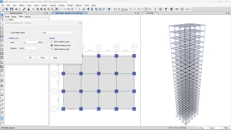
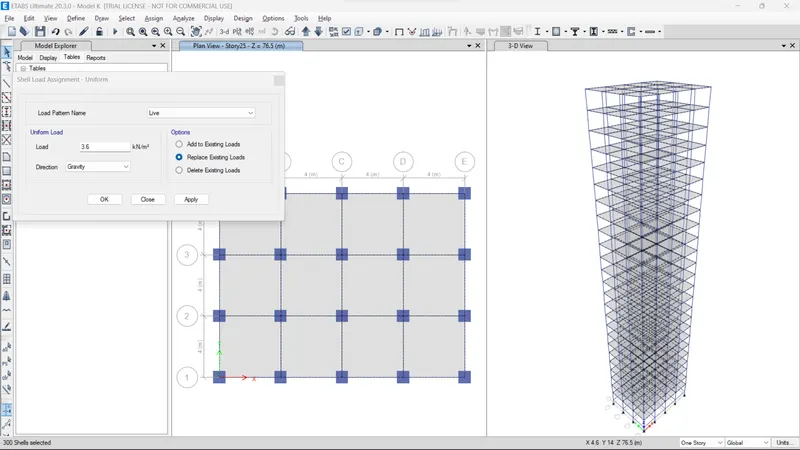
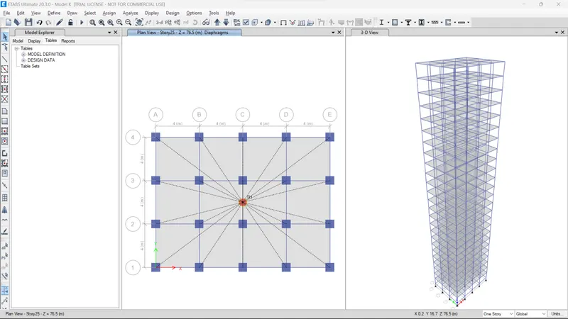
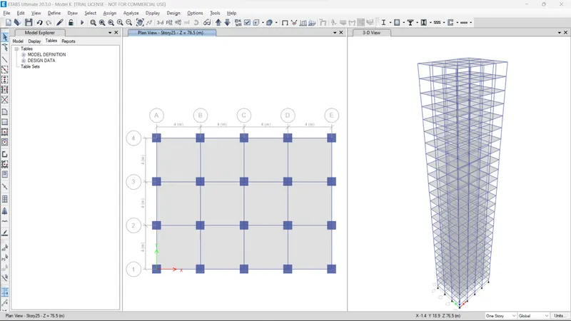
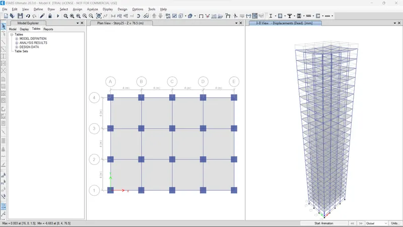
Result of Modal K
Modal periods and frequencies
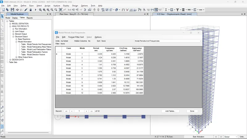
Modal Participating Mass ratios
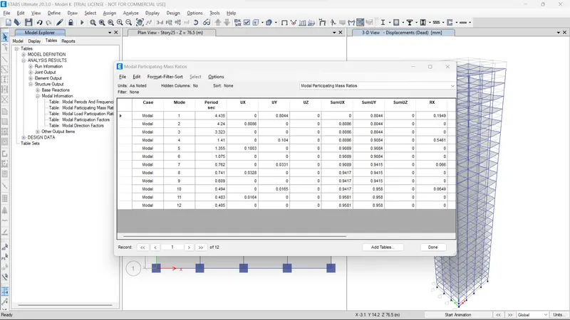
MaximumStory displacement EQx
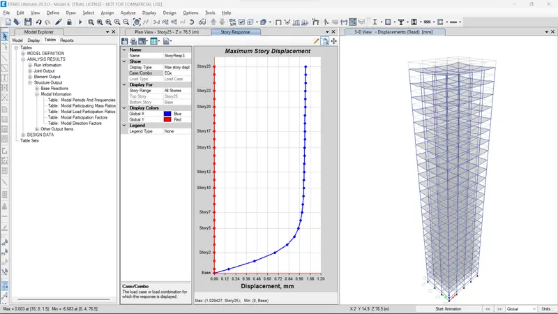
MaximumStory displacement EQy
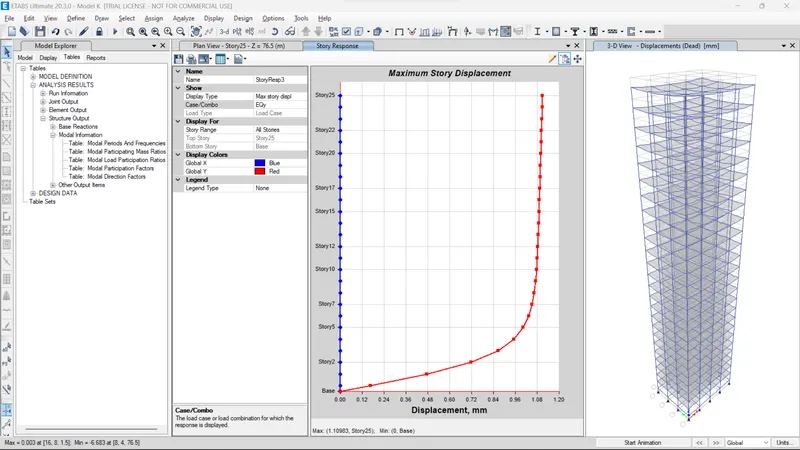
RESULT:-
1. Effect of stiffness on T: Compare fundamental natural periods of buildings E & F as well as G & H
| Criteria | Model | Analysis result |
| Effect of stiffness on time period |
Building E (10 Stories with varying column sizes) |
1.73s |
|
Building F (10 Stories with Uniform column sizes) |
1.73s | |
| Effect of stiffness on time period |
Building-G (25 stories with varying column sizes) |
4.17s |
|
Building-H (25 stories with varying column sizes) |
4.41s |
| Conclusion:- As we see in varying column sizes and uniform column sizes time periods are not very bigger differences. it is not any concerning point. |
2. Effect of mass on T: Compare fundamental natural periods of buildings H, J, and K.
| Criteria |
Model |
Analysis Result |
| Effect of mass on time period |
Building-H (25 stories with 3KN/m^2 imposed load) |
4.41s |
|
Building-J (25 stories with 3.3KN/m^2 imposed load) |
4.42s | |
|
Building-K (25 stories with 3.6KN/m^2 imposed load) |
4.43s |
|
Conclusion:- As we see changes in imposed load it will change periods of time will also change but the difference is not greater |
3. Effect of Building Height on T: How do the fundamental natural periods of Buildings A, B, F, and H change with a change in building height
| Criteria | Model | Analysis Result |
| Effect of building height on time period |
Building-A (2 Storey) |
0.5s |
|
Building-B (5 Storey) |
1.03s | |
|
Building-F (10 Storey) |
1.73s | |
|
Building-H (25 Storey) |
4.41s |
| Conclusion:- As we see No of the story are increase the Time Period of the building also increases |
4. Effect of Column Orientation on T: How do the fundamental natural periods of Buildings B, C, and D change with a change in column orientation
| Criteria | Model | Analysis Result |
| Effect of column orientation on Time Period |
Building-B (All floors column size 400X400) |
1.03s |
|
Building-C (All floors column size 550X300) oriented in X-direction |
1.145s | |
|
Building-B (All floors column size 400X400) oriented in Y-direction |
1.12s |
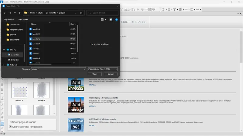
Open-C
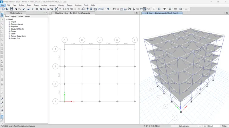
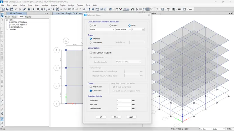
Goto Deformed shape
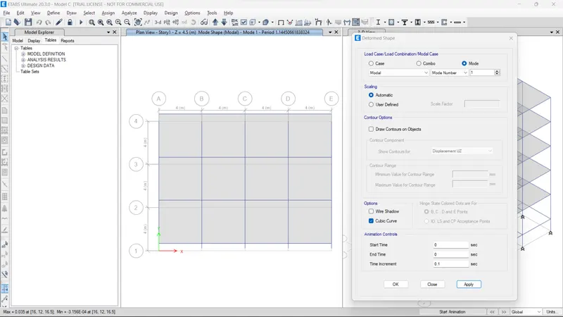
Select Mode 1
Press Apply
Deformation will goes along +y-direction
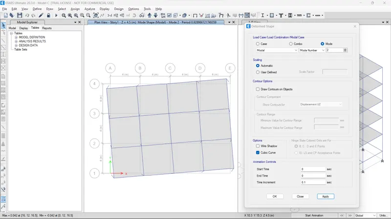
Select Mode-2
Press Apply
Deformation Comes in rotation form about z-axis
Open Model-D
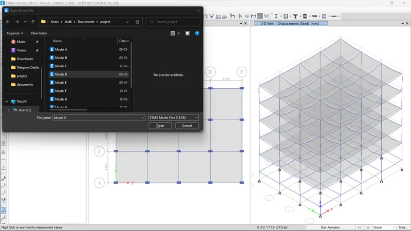
Goto deformed shape
Select Mode-1
Press apply

Deformation goes along -ve X-direction
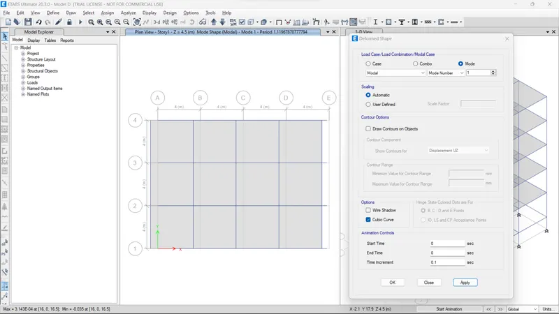
Select mode-2
Deflection goes to +ve X-direction
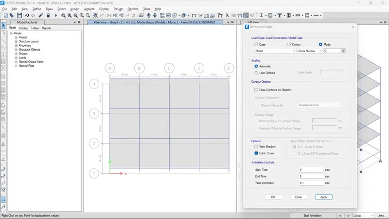
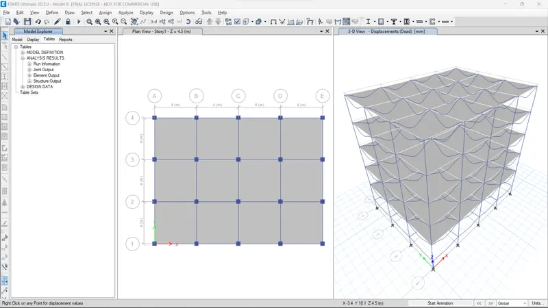
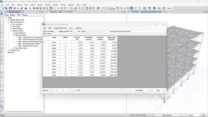
5. Effect of Flexural Stiffness of Structural Elements on mode shapes: Compare the fundamental mode shape of Building B in two situations when flexural stiffness of beams relative to that of adjoining columns is very small versus when it is large.
Effect of flexural stiffness of structural element on mode shapes.
| Criteria | Model | Case | Analysis Result |
| Effect of flexural stiffness of structural element on mode shapes. | Building-B | Flexural Stiffness of beam close to nil (Zero inertia) | 2.62s |
| Full Flexural Stiffness of beam (Regular) | 1.03s |
| Conclusion:- As we see Flexural stiffness of the beam becomes nil(only 10%) time period will be Greater than double the regular building. |
Open Model-B
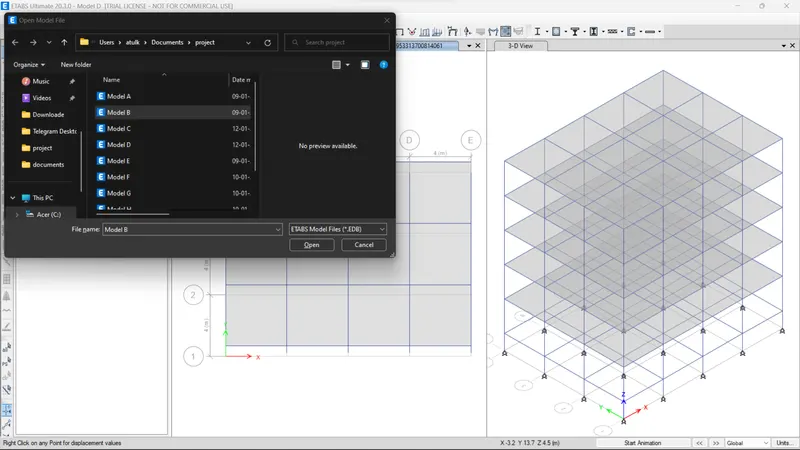
Goto Frame property
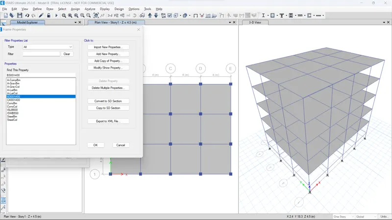
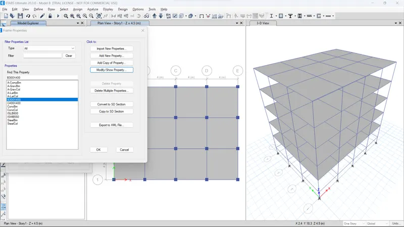
Select Beam B300X400
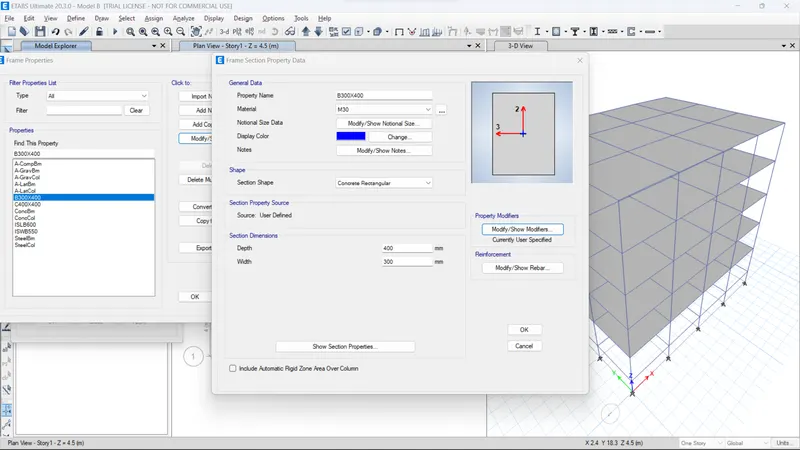
Goto Modify property
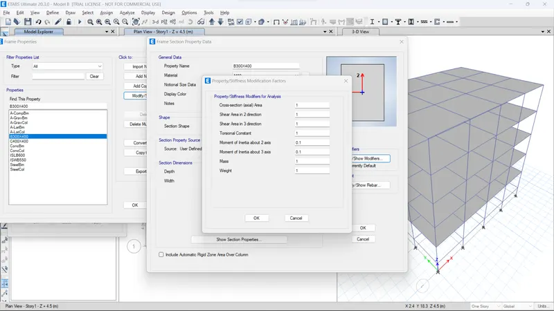
Then goto Modifier factor
Give Moment of inertia about 2 axes -0.1
and Moment of inertia about 3 axes -0.1
Press ok
Then go to Run Analysis
See the result
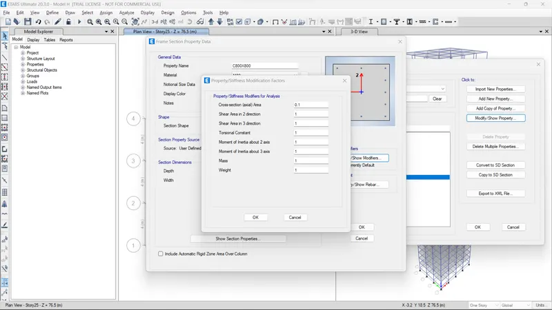
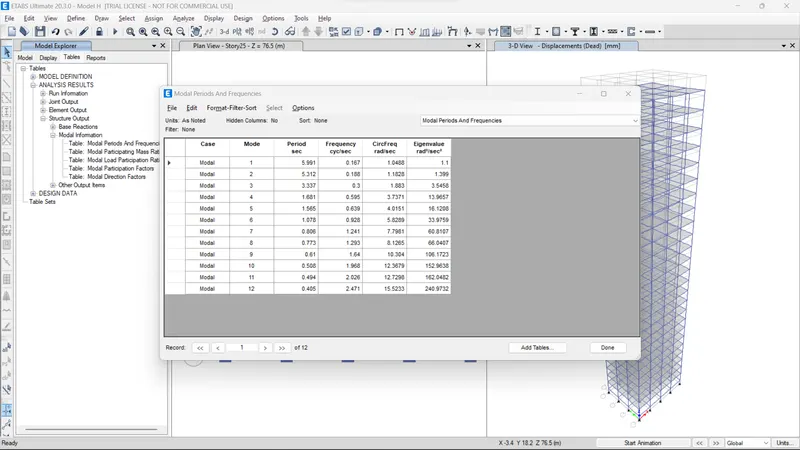
6. Effect of Axial Stiffness of Vertical Members on mode shapes: Compare the fundamental mode shape of Building H in two situations when the axial cross-sectional area of columns is very small versus when it is large.
Effect of axial stiffness of vertical members on mode shapes
| Criteria | Model | Case | Analysis Result |
| Effect of axial stiffness of vertical members on mode shapes | Building-H | The axial cross-section for columns is close to nil(Zero axial areas)(10% assign) | 5.99s |
| Full Axial cross section for column(Regular) | 4.41s |
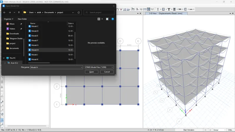
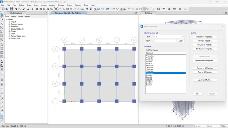
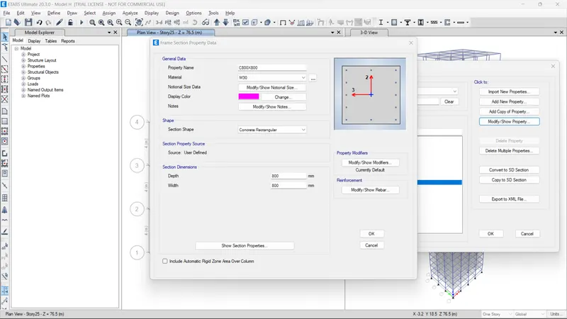
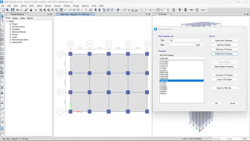
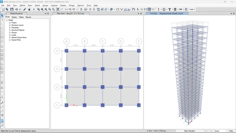
Open Model-H
Goto frame properties
select Column C800X800> select modify Property
Then Goto Modifier >
Give column section axis -0.1
Press ok
Press ok
Then Run analysis
7. Effect of Degree of Fixity at column bases on mode shape: Compare the fundamental mode shape of Building B in two situations when the base of columns is pinned versus when it is fixed
Effect of degree of Fixity at column base on mode shape
| Criteria | Model | Case | Analysis result |
| Effect of degree of fixity at column base on mode shape | Building-B | Column Support pinned (Regular) | 1.03s |
| Columns support fixed | 0.94s |
Open model -B
Goto base story
select all column base
Goto restrain> select Fixed support > press ok
Then goto run the analysis