Project 1 : CFD Meshing for Tesla Cyber Truck
Objective:
- Find and fix all the topological mistakes in the model of the Tesla Cyber Truck Car that has been provided.
- Creating a surface mesh is the goal.
- Develop a wind-tunnel-like scenario for the Tesla Cyber Truck.
ANSA:
The automotive industry makes extensive use of the computer-aided engineering tool known as ANSA for finite element analysis and computational fluid dynamics (CFD) analysis. BETA CAE Systems is the company that created it. A number of BETA CAE Systems subsidiaries and business agents work together to disseminate the software all over the world.
ANSA ensures that the connection between the CAD geometry and the FE mesh remains intact. This indicates that the FE meshes are superior representations of the geometric parents to which they belong. Additionally, it is simple to maintain and update any changes in the geometry by merely rewriting the updated region rather than starting from scratch to recreate the FE. This makes it straightforward to do so.
It includes many unique algorithms for meshing that are appropriate for computational fluid dynamics (CFD) simulations as well as structural models. Automatic net generation for structural analysis was the original meaning of the acronym ANSA, but the software has rapidly expanded beyond that scope. TOPO MESH, VMESH, DECK-SOLVER, MORPH, and HBLOCK are the names of the many operations that can be accomplished with the help of ANSA's broadly six menus.
ANSA contains a variety of modules of the following types:
TOPO is an abbreviation that stands for "Set of Tools for Optimizing and Polishing Geometry."
Tools that may create Surface Mesh or 2D Mesh are referred to as MESH.
VOLUME MESH is used to generate a solid or three-dimensional mesh.
SOLVER DECKS are tools that are constructed on the back of several solvers, such as ABAQUS, RADIOSS, and ANSYS, amongst others.
MORPH is an advanced tool that allows for more precise capturing of geometry during the meshing process.
- Method of solving the problem:
In order to solve the problem, we will follow the approach below,
- Import the model created in CAD.
- Locating and correcting any topological or geometric flaws that have been made.
- Inspecting the Geometry.
- The installation of any necessary PIDs
- Specifying the dimensions of the element's length.
- The CAD model requires the setting of the mesh parameters, the selection of the meshing type, and the generation of the surface mesh.
- Putting an end to the faults that have been plaguing the surface mesh.
- Developing the wind tunnel in preparation for an exterior flow CFD study and developing the surface mesh for the wind tunnel.
- Let us begin the process of fixing each problem one at a time by following the procedures above:
1.) Importing CAD the model :
- In order to import the CAD model, please follow the instructions below.
Navigate to the file menu, select open, then browse to the location of the CAD model, select it, and then click open.
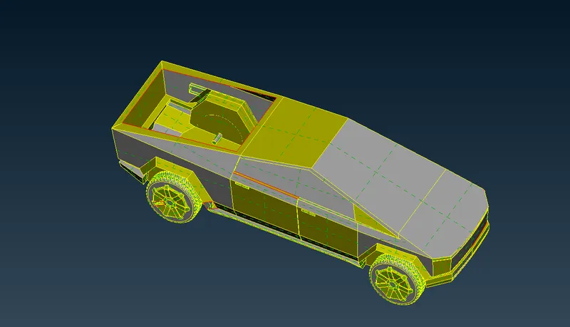
- Now that we know that the previous picture just depicts a single con, we can execute topo on the whole model and get a more accurate depiction of the model and its individual flaws.
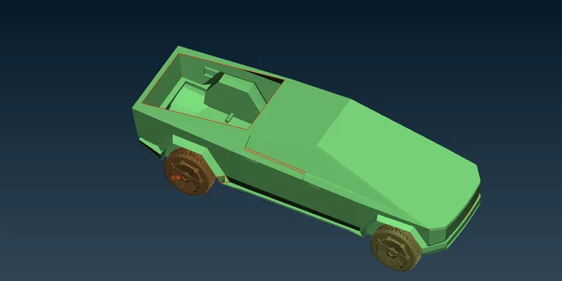
- When we first viewed the imported model, it was in ENT mode. However, by switching to PID mode in the layout's lower-right corner, we were able to see the PID mode, which is shown in the figure below, which is of our BMW M6 car.
- Now that we've switched to the wireframe view, we can more easily see the topological flaws in our model.
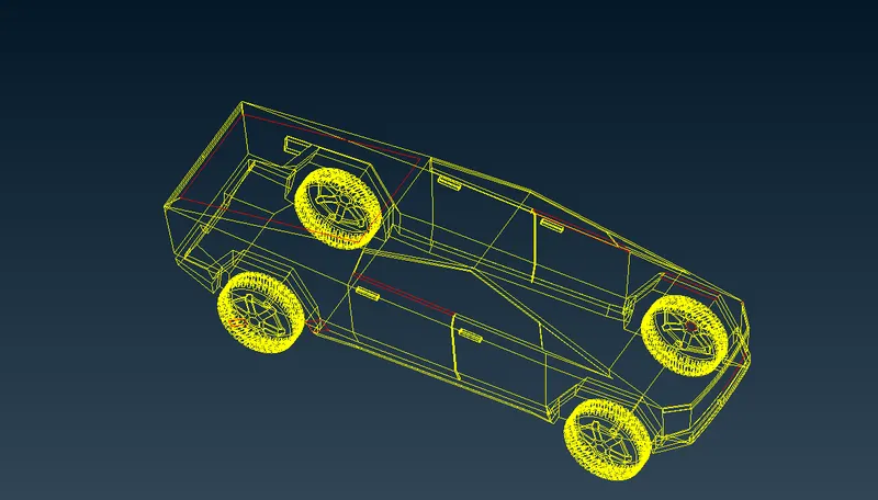
- Our model's flaws, such as missing connections, become readily apparent in wireframe view. Together, we can fix all of the topo faults.
- At first, there were a lot of errors, and each one of them has to be fixed in a methodical way, one after the other. To rectify the faults, separate selections are being made for each component of the automobile, such as its lights, wheels, windshield, body, and so on.
- We have to adjust all of the features so that we can acquire the whole interior of the automobile as one volume. Just as in the previous case, we are mostly concerned with the outside characteristics of the vehicle rather than its interior characteristics.
- Therefore, in order to keep the whole model as a single volume, we should only have double connections, and even with double connections, we shouldn't have a feature that is closed on both sides since this might result in the formation of a separate local volume there.
- Also, when you identify a little surface, erase it together with its neighbouring surface, and make a huge surface in its place so that we do not experience any quality criterion errors throughout the meshing process.
- Therefore, we will get rid of the surfaces that aren't required and either caused an error or led to the formation of a local volume.
3) A quick review of geometry:
- After correcting all of the topological defects, the geometry is examined using the tools available in the checks manager's geometry checks section.
- The figure below shows checks manager after conducting geometry checks. Here, we can clearly see that there are no problems present.
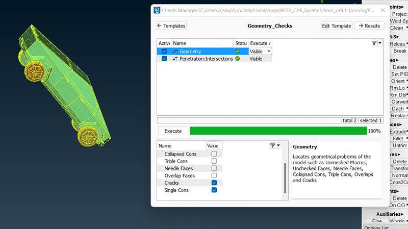
- The model is now ready for meshing, and we can safely assume that all defects have been fixed.
4) The settings of the relevant PIDs:
- This is done to distinguish between the components and to make it easier to work on the components independently. This is also done to designate names to distinct boundary conditions for various portions. We need to enable cross hatches before setting up PIDs.
- When you open up the properties manager at the very top, you will see that there are already some default PIDs allocated. It is necessary for us to generate new PIDs so that we may allocate them to our components. To create a new PID, right-click on the properties manager, then click new, then pick pshell twice, then give the new PID a name in the popup box, and then click ok. You may change the colour by double-clicking on the colour box, and then clicking ok.
- Using the same method, generate PID s for each of the components.
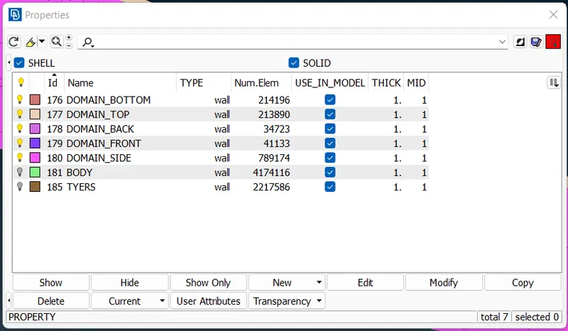
5) Deciding the element size or length as well as determining the mesh parameters, as well as forming the surface mesh and addressing the flaws in the surface mesh:
- Before we begin meshing, we have to specify quality requirements. In this step, we choose openFoam as the solver deck so that we can get the quality specifications of that solver.
- Since we have a variety of surfaces here, we will employ distinct quality standards for each of those surfaces. Additionally, the mesh length will vary depending on the degree of surface complexity and the total area of the surface. We set the element lengths appropriately, since a fine mesh for every element would be time demanding and would be computationally expensive. If the surface is tiny, we have to use the minimum goal length; if the surface is bigger, we use correspondingly.
- In the following, we outline the various quality standards (minimum length and maximum length) that apply to the various components.
FOR TYRES:
TARGET LENGTH: 3 MM
MIN LENGTH: 1 MM
MAX LENGTH: 5 MM
FOR BODY:
TARGET LENGTH: 4 MM
MIN LENGTH: 1 MM
MAX LENGTH: 6 MM
- Navigate to Mesh Generation > spot Mesh > tria > drag and select the required model > click on the scroll button or middle mouse button on mouse to mesh (or) we can directly select visible under the drop down menu of CFD mesh instead of dragging and selecting the entire model after first separating its components using NOT.
- Following the completion of the meshing process, we will pick the concealed mode in order to get rid of the off components of the PID in question.
- When you are in the concealed mode, you will be able to see the off components highlighted in the colour that you chose for that quality criterion in the menu for the quality criteria.
- After the meshing process, we will see that there are some off elements; we are able to get rid of the majority of them by utilizing reconstruct under shell mesh; however, if you still have some off elements, we will need to go to each site individually and clear that off element.
You may see more clearly by switching to topo mode after you have turned off the elements. If it is feasible to complete the task while in mesh mode, you should do so so that you do not lose any mesh.
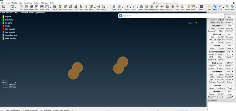
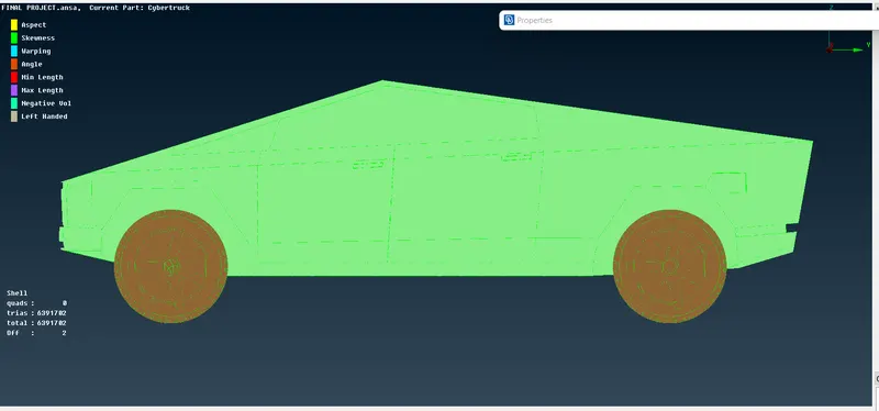
6) Establishing the wind tunnel in order to conduct a CFD analysis on the external flow and establishing the surface mesh of the wind tunnel:
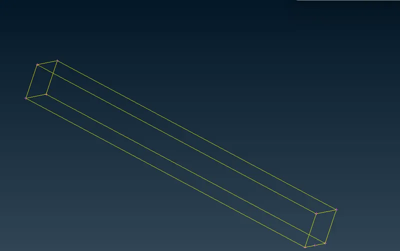
- In order to conduct CFD analysis on the vehicle's exterior flow, a wind tunnel needs to be built around it. In TOPO mode, a rectangular box is used as the basis for its creation. It is also important to pay attention to the dimensions of the wind tunnel in order to accurately capture the flow around the vehicle. The following is a rundown of the dimensions:
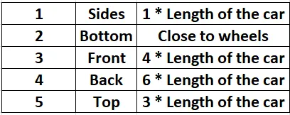
- Now, using these two surfaces, we create new surfaces on all of the volume's sides in order to form a wind tunnel.
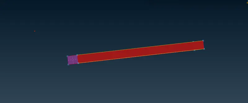
- Now we will construct the PIDs for the wind tunnel walls and assign them.
- We can see that PIDs are created and assigned in the image that is provided below.
- The image that can be found below depicts the wireframe mode of the wind tunnel that we have created.
- The next step is to finish assembling the surface mesh in the wind tunnel.
- Since the wind tunnel has been modelled at this point, the first step is to surface mesh it in such a way that the mesh size gradually increases from top to bottom.
- If we have a refined mesh ength at the top, then we will have a lot of cells, which will require a great deal of computational effort to solve.
- Because of this, we give varying mesh lengths.
- To accomplish this, go to the mesh utility menu and select the spacing option from the perimeters submenu.
- Choose the geometry biassing option, then set the dmin value to 20, the dimit value to 100, the facot value to 1.1, and select all four vertical perimeters. However, before we do that, we will surface the top part by providing it with a length of 100 mm, and the bottom part will have a length of 20 mm.
- The surface mesh should then be generated. In the image that follows,
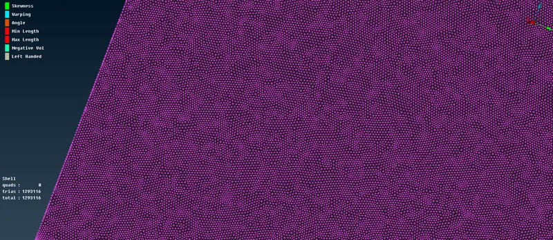
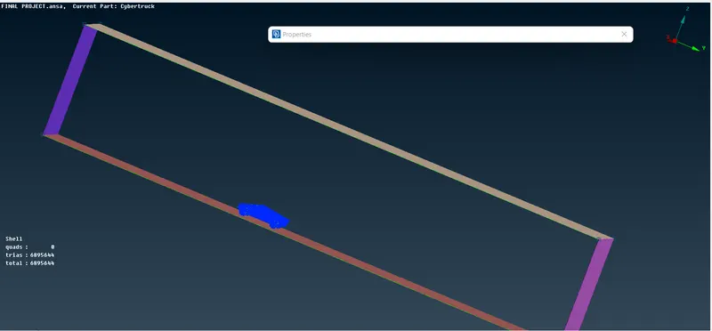
- In the image that follows, we can see that the surface mesh has been successfully completed for the entire model and the wind tunnel. The length of the mesh varies, growing longer as it moves from the bottom to the top.
- To control that we used Spacing for fine mesh varring length from 20 mm to 100mm.
The completed mesh can be seen in the image that follows.
The result of the learning is:
In this process of working on this project we have learned how to,
- locating and correcting any topological or geometric errors that have been made.
- Checking the geometry, configuring any relevant PIDs, and determining the element's size or length are all part of this step.
- Establishing the mesh parameters and quality criteria, deciding on the type of meshing to use, and producing the surface mesh for the CAD model are the steps in this process.
- Utilize the Quality criteria tool and educate yourself on the various options available under the shell parameters. Some of these options include skewness, minimum length, maximum length, maximum angle, and minimum angle, amongst others.
- Using a variety of tools, we were able to fix the errors such as skewness, minimum and maximum lengths.
- Establish the Wind Tunnel in accordance with the given dimensions for the purpose of conducting an external flow CFD analysis and surface mesh of the wind tunnel.
Concluding remarks:
- In order to carry out an external aerodynamic analysis, the imported CAD model of Tesla cyber truck was given a topological cleaning and correction of any surface errors that were feasible.
- The required element size is applied to the newly generated surface mesh.
- Reconstructed the mesh so that it meets the requirements for the mesh quality at the corners and intersections of the edges.
dealt with the issues that arose as a result of the mesh. - Built a wind tunnel for use in conducting external aerodynamic research.
Google drive link for challenge file folder :
https://drive.google.com/file/d/1S9bN4MVXEIGIb53PbYHKyOA4aoXwpatx/view?usp=sharing
https://drive.google.com/file/d/1S9bN4MVXEIGIb53PbYHKyOA4aoXwpatx/view?usp=sharing