Project 1 : CFD Meshing for Tesla Cyber Truck
AIM:
To check and clear all the geometrical & intersection errors in the given geometry. And to assign the PID for each component in the geometry. And also to do the surface meshing of the geometry consider the external flow analysis. Then have to create the wind tunnel using proper calcualtions for doing the external flow analysis.
IMPORTANT TOOLS USED:
- Quality criteria ---------> Skewness, Min length and Max length (To validate the generated mesh is upto the quality needed)
- Perimeters ---------> Spacing ---------> Manual (To gradually increase the size of the mesh generation with respect to the growing factor from the Minimum length to the maximum length)
PROCEDURE:
1. Geometry Checkup:
After loading the geometry into the ANSA, initially we have to check for the dimensions of the geometry. Then we have to do the Faces --------> Topo option to properly join the faces. Then using Hot points ---------> Delete option we have to delete the unnecessary hot points in the geometry. After doing this initial setup we have to do Checks Manager ---------> Geometry checkup . By doing that we can get to know all of the geometric and intersection errors in the given geometry.
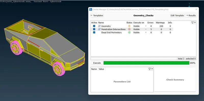
And then we have to closely watch the geometry for any errors in visual check. Then in this geometry if we seperate the car body into two from the middle. We can get to symmetrical body, so that we can do the work in ease and then we can mirror the part to get the full car body.
For doing that we have to go for Faces --------> Plane cut option and we have to choose the three exact centre hot point of the car to do the function. Then we can delete the one side of the car using Delete option.
2. Error Rectification:
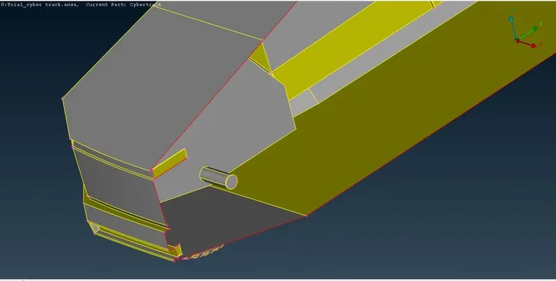
- After doing the plane cut option, some of the faces which are irrelevant to the geometry is there. So we have to carefully delete the faces using Faces---------> Delete option. On the particular image attached below we have to use Cut and Project Cut option for clearing the geometrical errors.
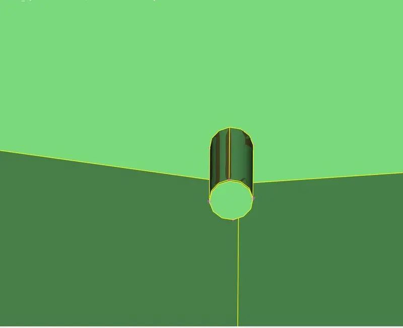
- Then the part of the car tyre and the body intersect with each other (attached image below). It is clear that intersection error happened between the two faces. So we have to carefully delete the unwanted faces considering the geometry.
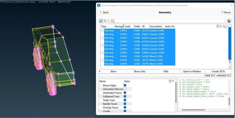
Thus all the geometrical and intersections erros are cleared in the geometry.
3. Assign PID:
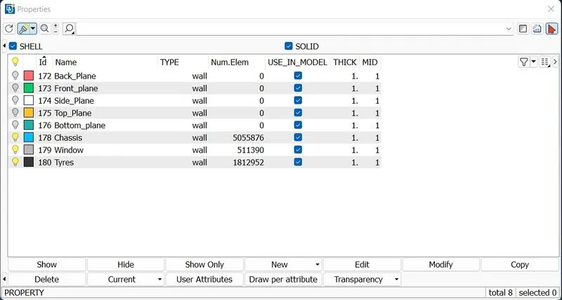
After the errors get cleared, we have to assign PID for the each component in the geometry. For that we have to go for Faces ---------> SET PID option, and then select the faces to assign PID. Then we can change the color for ease of identification.
4. Surface Meshing:
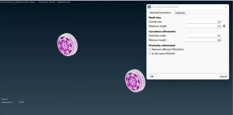
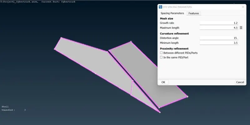
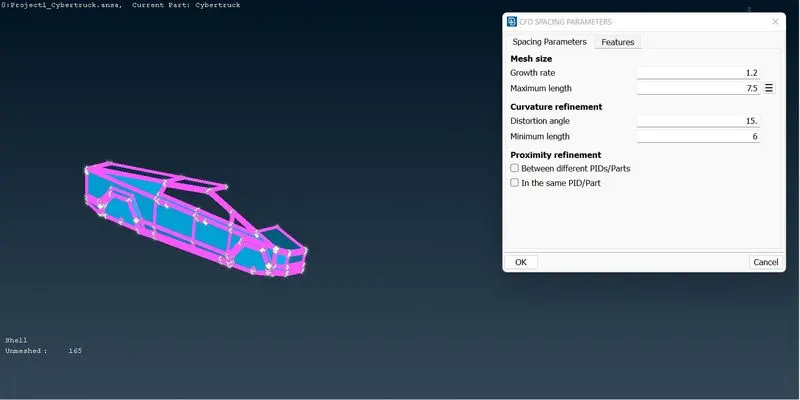
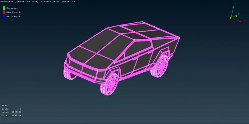
After assigning the PID we have to do the surface meshing for the each and every component in the geometry. For choosing the target length of the mesh we have to study the previous research paper and then we have to select it. So in this geometry I segmented it as Chassis, windows and Tyres.
For,
Tyres - 3mm Target length
Wind - 4mm target length
Chassis - 7mm target length
These target length is choosen under Perimeter -------> Auto CFD --------> Perimeters & Macros option. After done with the assigning of target length to the perimeters and macros, we have to select Mesh generation --------> Auto CFD ---------> Visible option to generate the mesh.
5. Quality Criteria:
By generating the surface mesh for each component simultaneously we have to check the quality criteria. For selecting the quality criteria, We have to go select the Quality criteria in the tool bar. By clicking that dialog box appears. On that we have to select the required parameter to be consider for quality purpose. In this we consider the Skewness, Minimum length and Maximum length of the macros.
For that we provide the value of Skewness as 0.5, Minimum length as 0.2mm and Maximum length as 9mm.
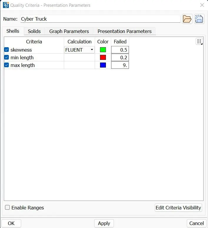
If the quality criteria is deviated from its given value, it will be shown as OFF elements. So after the meshing is completed there must not be any off elements in the geometry. If there is any Off elements present in our geometry, we have to clear it by choosing the option Improve by right click off element quality shown in the left bottom corner. On that Improve ---------> Reconstruct, Reshape, Smooth and Fix Quality options are there. So depending upon the required option we have to choose it and have to clear all the off elements in the geometry.
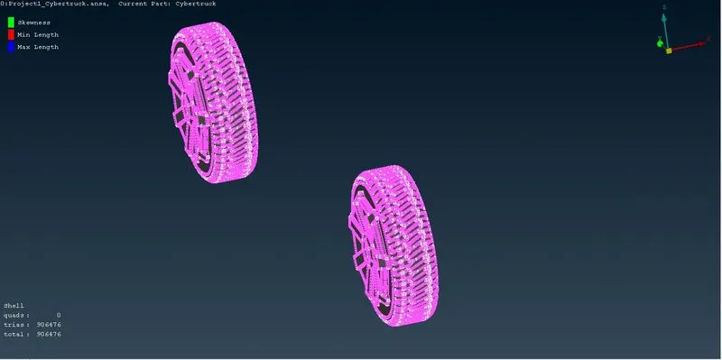
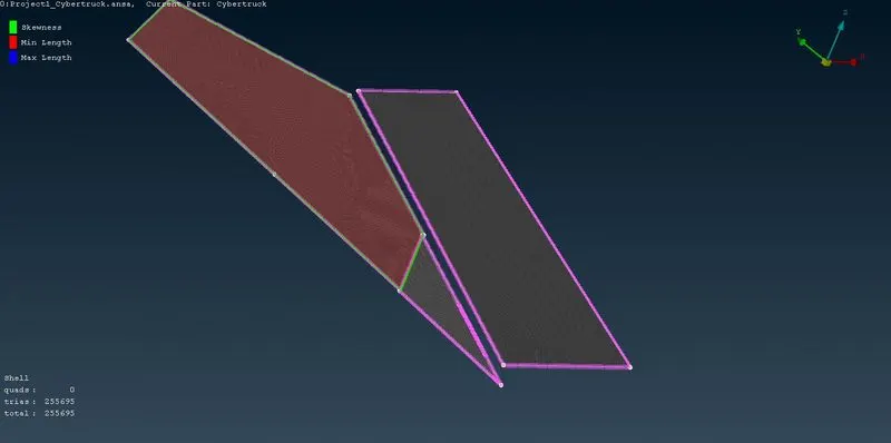
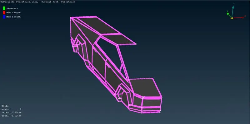
Thus by doing that we clear all the Off elements.
6. Mirror Option:
After successfully finishing the surface meshing and passing the quality criteria,now we can move for the symmetry option where we can make all the parts of the truck symmetrical to make it a full body.
For doing that we have to go for Transforms --------> Copy --------> Symmetry --------> Mirror 3 points plane option. By choosing the option we have to select the three hotpoints at the extreme edge of the body where we need to do the symmetry. After selecting that we have to click middle button in mouse to apply the changes.
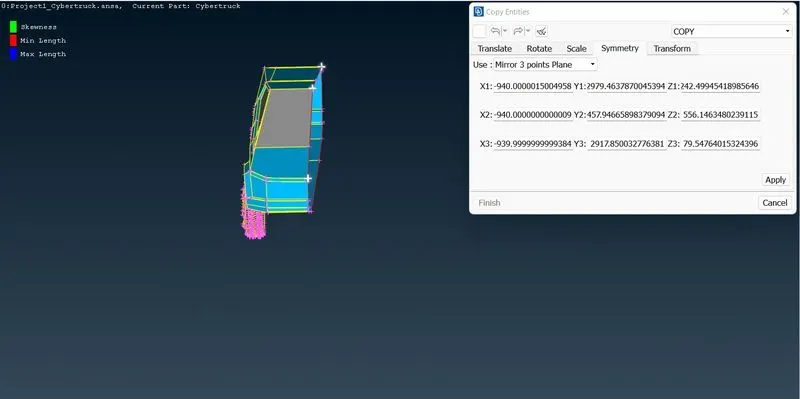
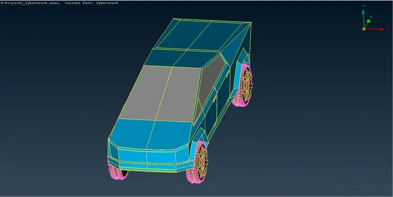
Thus we got the entire truck model.
7. Creation of Wind Tunnel:
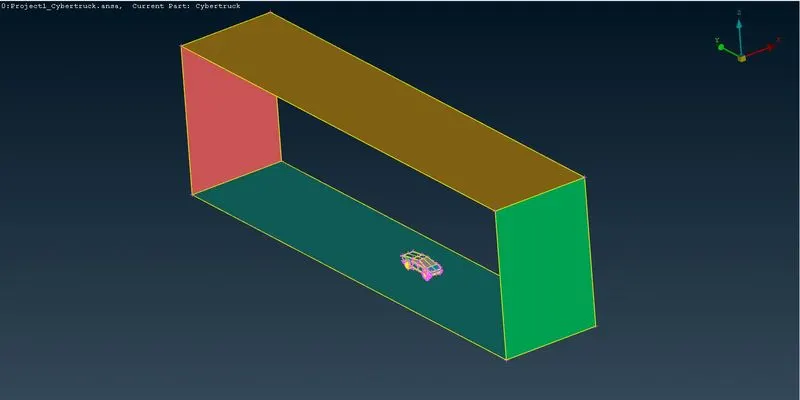
In this project for creating the wind tunnel we choose the distance of 4X to create Front plane from the extreme front part of the truck and for the top plane 3X is the distance considered from the topmost part of the truck and for creating the Back Plane 6X distance is considered from the backmost part of the truck. For the side plane at each side X distance is considered from the extreme side part of the Truck. Where X is the overall length of the Truck.
Then for creating the bottom plane, we have to create a point in the bottom of the truck in the centre of XY plane(ie., Exactly centre of the truck in XY). That point doenot interesect with the tyre. So in order to do that I create a point which is 1000mm below the body of the truck. From that point using Point -------> Relative option with respect to the calculation we have to put a point at the from and rear side of the truck.
After that using the Curve --------> Create option, we have to select the line and joining all the points to create a line. Then using the Faces -------->New option with respect to the line created new faces is drawn(Consider as the bottom plane).
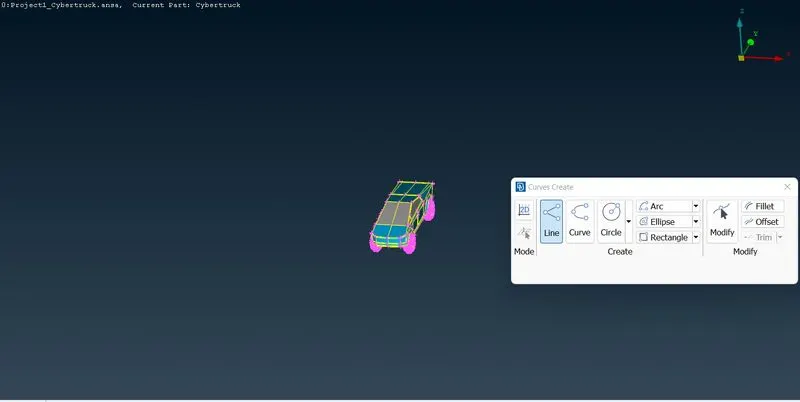
With respect to the bottom plane all other faces is created using the proper calculating distance.
8. Surface meshing of Bottom plane and Top plane:
After creating the wind tunnel, we have to do the surface meshing for the wind tunnel. For that first we have to mesh the bottom plane of the wind tunnel. The meshing is done by the command Spacing --------> Auto CFD --------> Perimeters & Macros. Then we have to put the spacing parameter. After that by clicking Mesh generation --------> CFD -------> Visible, we can generate the mesh.
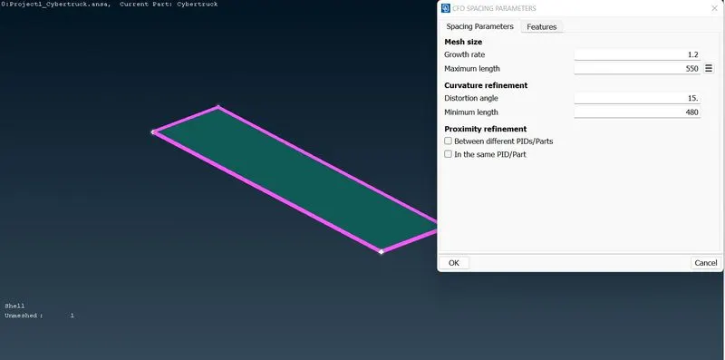
After the meshing have to be done for the top plane by the same procedure with different target length as we are planned to go for the incremental meshing for the wind tunnel.
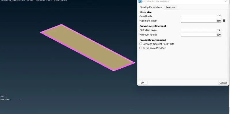
9. Incremental Meshing:
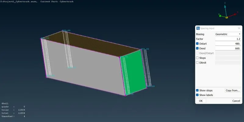
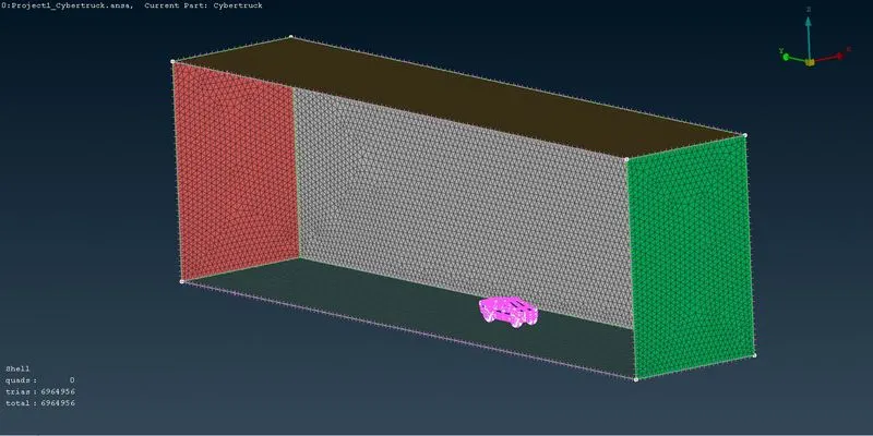
After that for the meshing of side plane, we have to go for the incremental meshing. That is done by simply clicking the Perimeter--------------> Spacing option. After that dialog box appears asked for the values. On that we have to input the values for Dstart and Dend. That is the range for the incremental meshing. The mesh growth happens based on the growth factor. After input all the values then we have to select the CONS on the faces where the mesh have to be generated. After that we have to go for Mesh generation -------->CFD -------> Visible option. Then the incremental meshing is generated.

https://drive.google.com/drive/folders/1AUwM1F7TOp2k839m85B3J5DKOUuna9Ky?usp=share_link
RESULT:
Thus by that with the given geometry all the errors are cleared and then PID is assigned respectively to the each component. Then the surface meshing is done for the truck. Then the wind tunnel is created and meshed for analysing the External flow analysis.