Project 1 : CFD Meshing for Tesla Cyber Truck
AIM: To make all geometrical errors clear and Assign appropriate PIDs. Perform meshing with the suitable Target length and element Quality criteria. create a wind tunnel around the truck.
OBJECTIVES:
1.clear all the geometric errors
2.asign the pids and mesh the patrs with the suitable target lengths.
3.the create a wind tunnel.
PROCEDURE:
1.first i inport the madel into the ansa software and i convert veiw of wire frame into solid frame. then i look after the all error in the given model.
2.then i unwanted surfaces inside the body of the turck, then i check the geometric checkup to show the all the error of the parts.
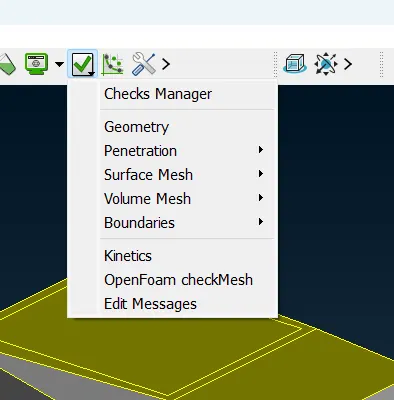
fig:geometry checkup option.
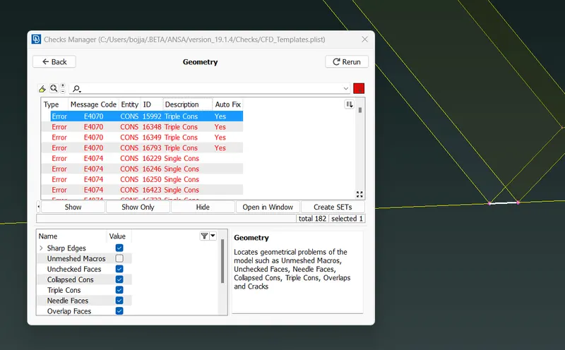
fig:geometry errors.
3.there is lot of the error in the singlecons ,few triple cones , mixed cones and unwanted surface as show in the below figure.
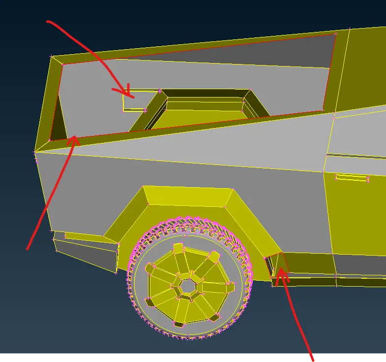
fig:single cone and unwanted surface inside the truck.
4.then i used the tool "new" in the topo deck to remove the single cons to to place new surface on the hole and then i also used "paste" option in the topo deck to convert the single cons into doubles that are not join cones.
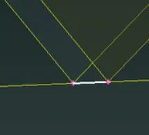
fig:single cone error i used paste option.
5.then i went to the delete the unwant surfaces the by using the "universal delete" option on main deck on display.then the deleted surface make some hole on the surface that are close by using the option called "new faces" on the topo deck.
6.then i close the holes by new option then it show some popup on the display to choose the method of closing the hole i used cones option. on that popup if option like fitted,curved and cone etc.. are there selete the suitable to the hole.
7.And therte also a another option on the topo deck to close the hole that is "fillhole".
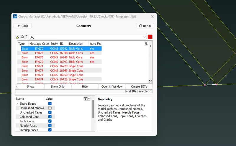
fig: showing the triple cone error.
9. then i went to the geometric check to check the error then it show the triple cone error. here i done the deleting the unwanted surface that causing the triple cone. then the cone is converted into the double cone.
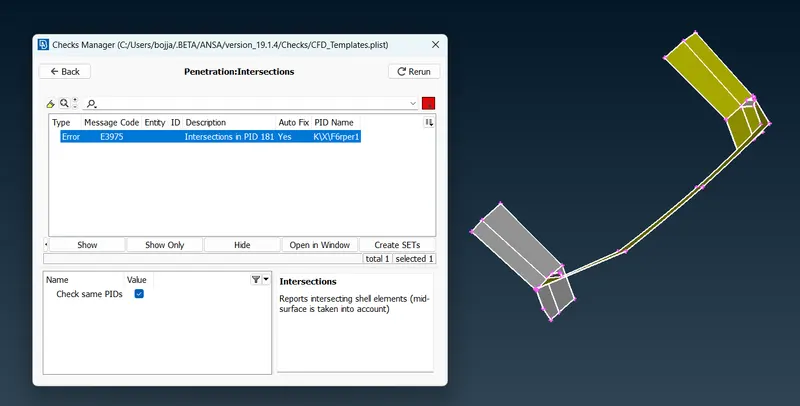
fig:penetration errors.
10.here i got few penetration errors that are in the front possion of the truck,then i deleted the parts that are causing the penetration error and i made the new surface to remove the penetration error.
11.here i not used the plane cut option because their is less no of errors and also the "symmetry" option is isalso not used here . this option is help to clear the error on oneside of the body then another side of the body is made same by using the "symmetry" option.
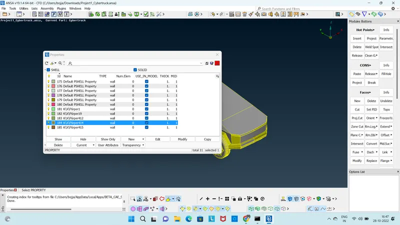
fig: Before asigning the PIDS.
12.then i went to asign the PIDS on the each part of the truck. then i want to the option pIDS on the main deck it show me a popup that have the all the PIDS that not asigned by me. then i created the few new PIDS that are wheels , body , windows and lights.
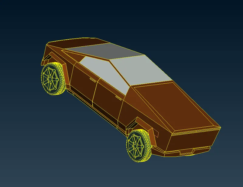
Fig: this is the figure after asigning th PIDS and color to the PIDS part.
13.while asigning the PIDS the have given the each PIDS with different color on the parts of the truck that is showing in the above figure.
14.then i went to mesh truck by according to asigned PIDS on the pids list.first i went to mesh the window and wheels at at time because they having the same traget length.
15.first i went to the option called mesh deck and i click on it to change the topo deck into the mesh deck then i get all the mesh tools to performe the meshing operation.
16. then went Quality Criteria and i set the all the Quality Criterias like skewness 0.5 and then minimum and maximum traget length and all with the color indication.
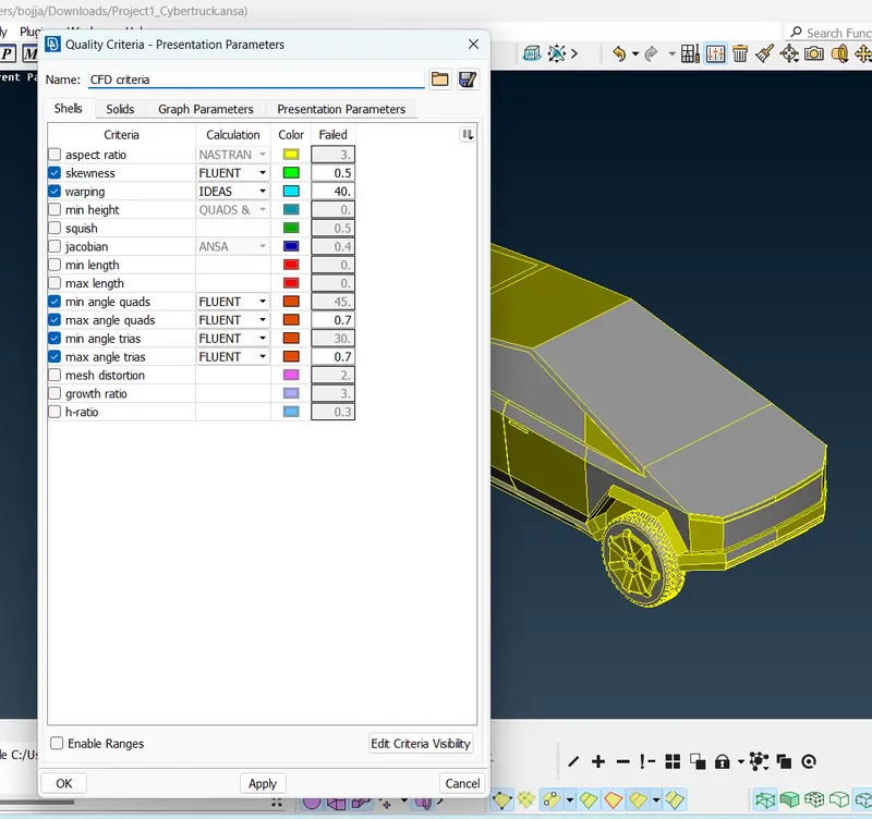
fig: Quality Criteria setup.
17. then i went to set cfd parameters setting option that is on the main deck to set the minimum and maximum traget length and to set type of meshing element.
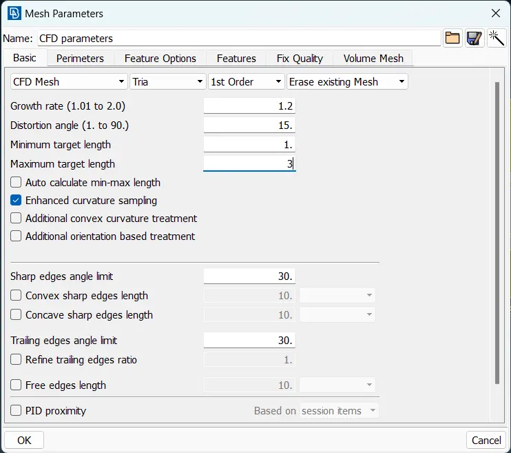
fig: cfd parameters setting
18.then i went to meshing part after all setup of the Quality Criteria according to the required mesh parameters.
19. i selected the wheels and windows then i parameters are set according to the traget length min is 1mm and max is 3mm.
then i went another option called "length" on the mesh deck the show me another popup parameters and micros by click on the each one and select the whole the body and click middle button of the mouse.
20. then i went to the another option called "spot mesh" by click on long press then i select the visible option then it take time and show me the on them.
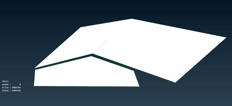
fig: windows with mesh.
21. then same for the wheels also with same traget length i repeat the same steps.
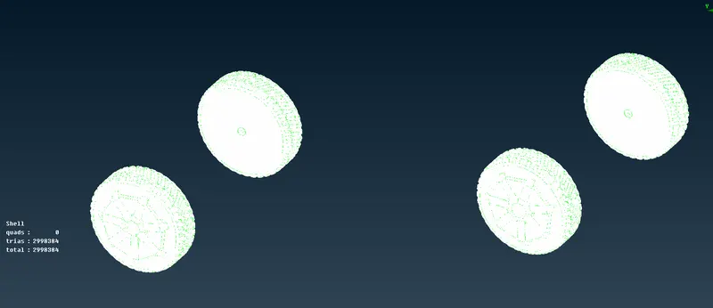
fig: wheels with the meshing
22. Before i mesh the body i went to "freeze" to not chang the mesh criteria of already meshed parts then i went to the body part here i changed only the cfd parameters only then and i repeated the same procedure to the mesh the body. the min traget length is 2 and max traget length is 4mm.
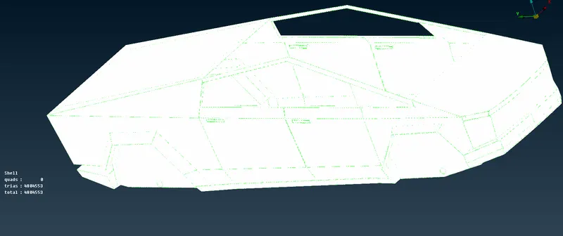
fig:body with the mesh.
23.then i used all the mesh parts are under freeze position and i went to mesh the ligths with the traget length of 4mm here i changed the cfd parameter min is 3mm and max is 5mm traget length.then i repeat same procedure has like body.
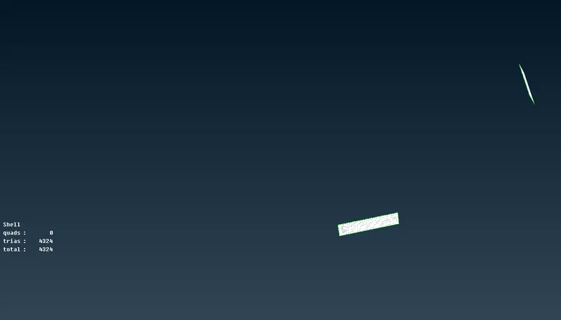
fig: ligths with meshed
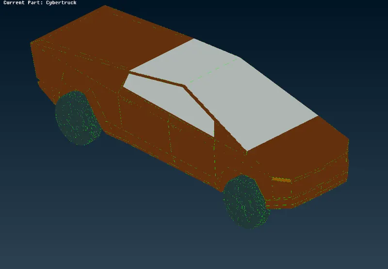
fig: after done with the meshing of the truck.
24.then i set the all "off element" by clicking on the off elements on the lift side down then i went to the option recontruction on the popup after click on the off elements.
25.then went to topo deck to create the wind tunnel around the truck. i click on the option "relative point" here i set the distance in x or y or z direction according point requirment.
26. then all points i have creted on the bottom of the truck according to create the rectangle plate on the bottom of the truck. i created the six points three points on front side and rear side three points. then i have join all the to make a rectangle shape and i create a plane by using the all the curves by option called "new".
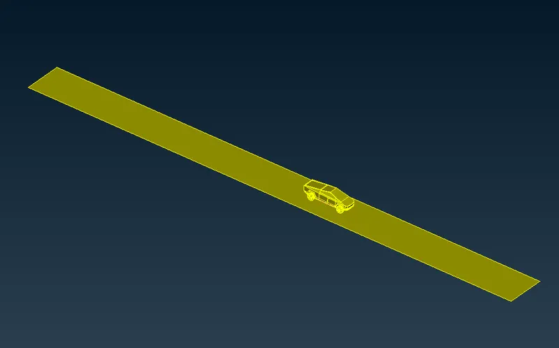
fig: base of the wind tunnel.
27. here i used the "offset" option on the topo deck by using this option i created the top side of wind tunnel plate by click on the option it ask to select the element after selection it show the direction according the direction the + and - is taken.
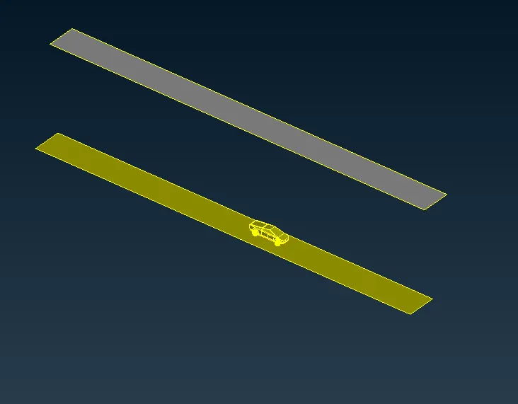
fig: top plate of the wind tunnel
28. then the remaining sides is created by new option.
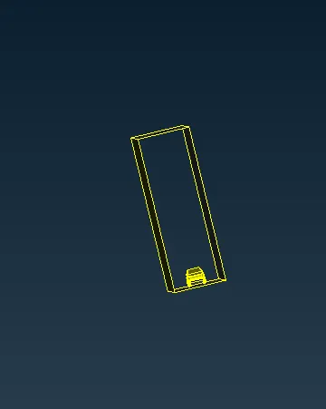
29. then i done the same for the front and rear side plates.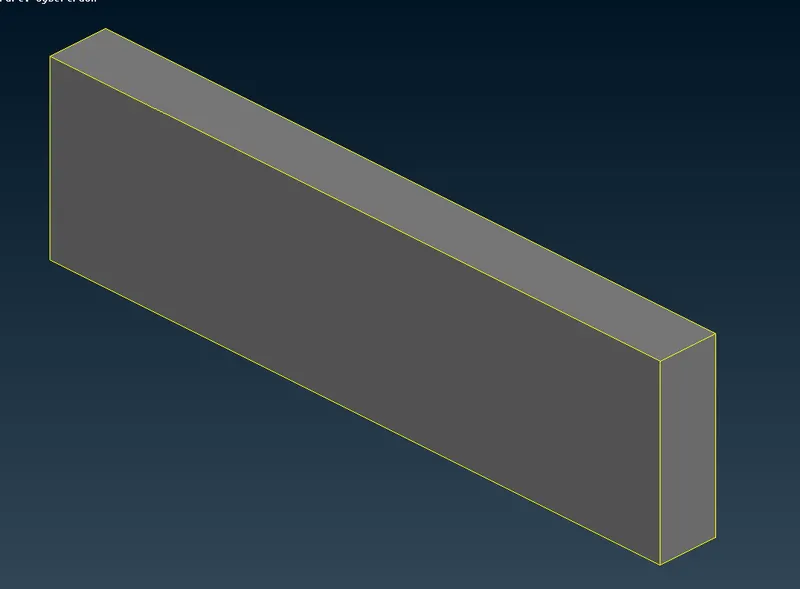
fig: complete wind tunnel.
30.Next i went to the mesh the wind tunnel the base plate with the 20mm and the 100mm with top plate. themesh the top and base plate is same but in case of the side,front and rear plates will be different.
31.In the mesh deck the option called "spacing" in list of perimeters. in that spacing long press that show the popup of "manual" method i selected. then it show another to set the mesh traget length from which length to which length. here i given the 20 to 100mm because the base plate is 20mm and the top plate is 100mm.
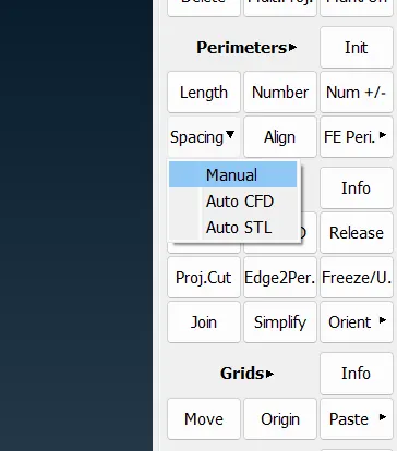
fig: spacing option.
32.then i went to the spot mesh option on the topo deck i selected and i click on the visible option on the popup. then is show the meshing on the wind tunnel. then i used regenerat option on the mesh deck to get good mesh but it not work. then i set the all "off element" by clicking on the off elements on the lift side down then i went to the option recontruction on the popup after click on the off elements. then i "unfreeze" all the parts.
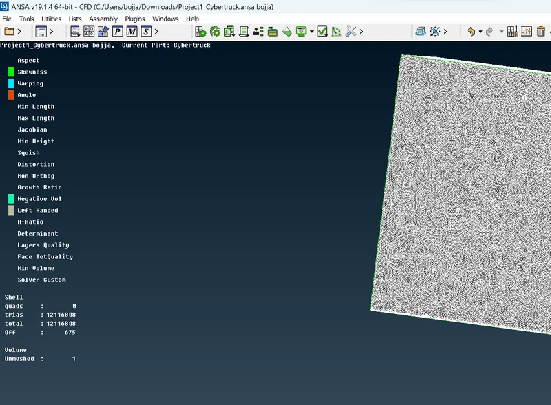
fig: after done with mesh and the no. of off elements are very low.
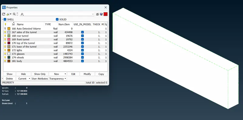
fig: after auto detection of volume by ansa (166 PID number).
33. then i went volumetric meshing option then the deck is converted into volumetric mesh deck, then i selected the option called "define" this is used to auto detection of the volume for the volumetric meshing.
34.here i deleted unwented volumes for the list, but here i need only on volume that is whole volume with the wind tunnel.
but i didnot done the volumetric meshing because it take lot of time (2days).
LEARNING OUT COMES:
here i learn that get to get the diferent size mesh on the single surface. i know how to clean the all the geometric errors of the model. then i learn to make volumetric meshing and asigning the pids.
RESULT:
hence i done the all geometrical clean up,i done 2D meshing ,creation of the wind tunnel is done i got the auto detected volume of whole body along with wind tunnel volume.
CONCLUSION:
i came to know that to do the volumeteric meshing the 2D meshing and geometerical clean up is must and should required. if the single cones in the model it will cause to detection of wrong volume to do the volumetric meshing.
PROJECT link:
https://drive.google.com/file/d/1N1XeYdSB51NQy1X_gSJMjeauWR8Pmdgk/view?usp=sharing