Project 1 : CFD Meshing for Tesla Cyber Truck
Aim:
To develop surface mesh over the surface of the given Tesla Cyber Truck model.
Objective:
To check for geomentrical errors in the given model and eliminate if any the assign PIDs and generate surface mesh over selected PIDs with different target length. The model is the verified using quality criteria.
ANSA:
ANSA is an advanced CAE pre-processing tool for Finite Element Analysis that provides all the necessary functionality for full-model build up, from CAD data to ready-to-run solver input file, in a single integrated environment.
Procedure :
Geometry Cleanup
The given CAD model is imported to ANSA using import option. Then we increase the resolution of the model to precisely capture the edges, using perimeter options under setting. Further we delete excess hot points to avoid complication during mesh generation. The we visuvalise the imported model using Entity option and later under wireframe mode to see for visible errors such as Single and Triple CONS.
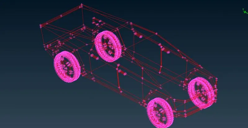
As we can see the entire geometry is of single CONS majourity of this can be due to the CONS of adjucent surface not being properly joined, we can solve this by doing TOPO for the whole geometry.
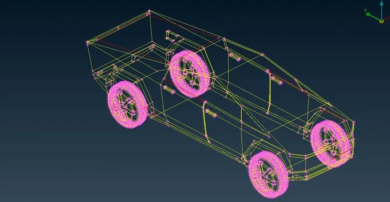
Since the entire model is axi symmetry about Y-axis therefore we can split the model into half therefore we can do the geometry cleanup for the half part and lated copy that model to have a proper model, this would save us a lot time. We first insert hot point over the surface of the body as we have to define the exact allignment of the cutting plane with the help of hot points. We then choose
Face> Plane Cut> Single>Choose hot points and select the half part to delete it.
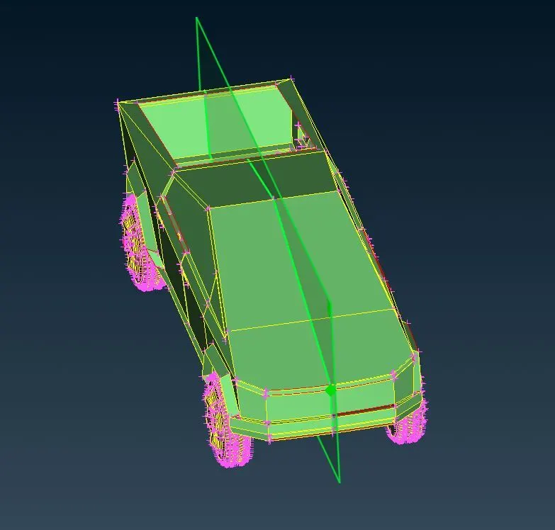
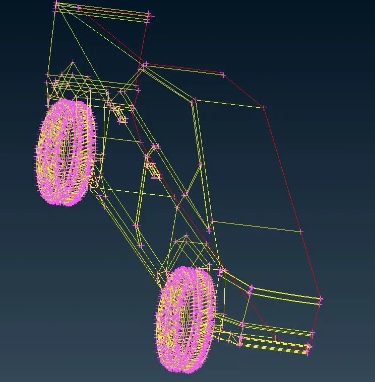
Now we have the exact half model , we use this model till mesh generation. For any cfd model to have a converged solution ANSA does not allow Single and Triple CONS. So as we can see there are still some Single CONS present on the topology, we have to eliminat them by using the tools provided by ANSA this include TOPO, New, Curves, Universal Delete, Project Cut, Extend, Intersect, Cut etc,. In this paticular geometry we have to perform a external simulation model. Now to identify the exact number of geomentrical and Intersection errors we co for geometry check-up.
Intersection errors happen when a surface intersects and penetrate through an other surface.
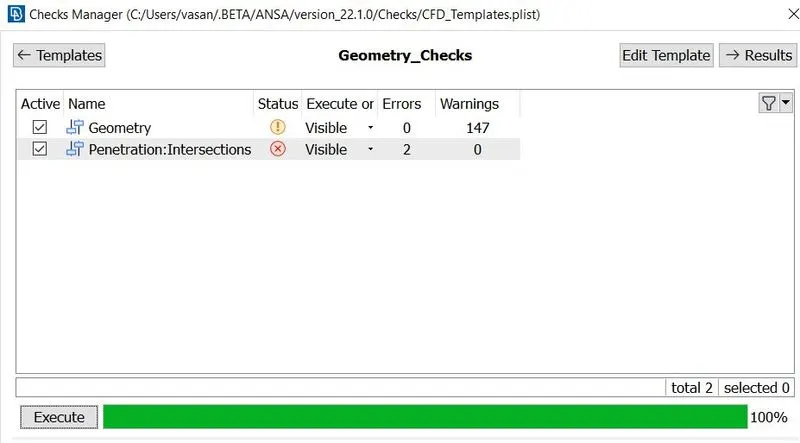
There are couple of intersection errors and many Single CONS. First we take a look into the visible Single CONS as it is simple to eliminate by creating new surfaces by selecting CONS within wich the surface confined. Since this is an external simulation model we are very much concerned about the external edges and surfaces and we want to capture it perfectly. Now to intersection errors one such error is shown below.
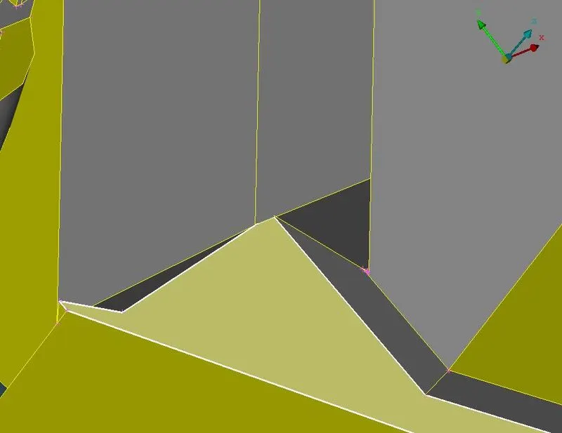
As we can observe this part of the geometry is with complex small surfaces and the surface is penetrating through another. We have to delet and have a proper and neat surface here by also maintain the external surfaces as close as possible.
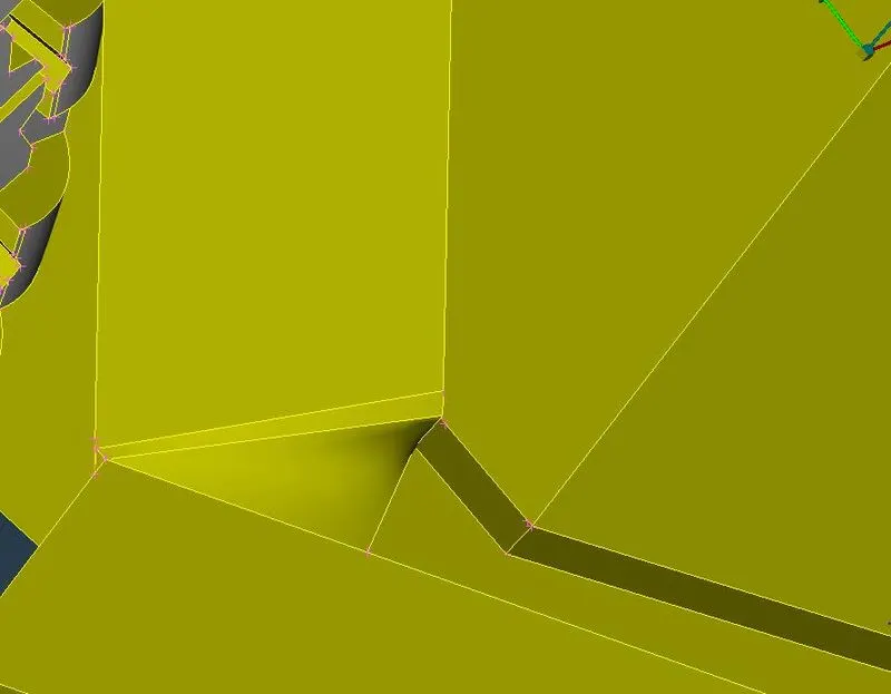
Next we can further reduce the single CONS by deleting the overlapping surfaces and filling the gap between surfaces using fill hole option. Sometimes the single cons does not have common edges in that cases we use paste option to fill the holes. We can isolate a paticular surfaces and then work on further clean-up on it. Some errors will point to a collapsed CONS where the ends of different surfaces does not meet properly or the creater new surface will have one unselected edge. And we have to delete small surfaces and edges and make it as one big surface so that the created mesh elements will be proper.
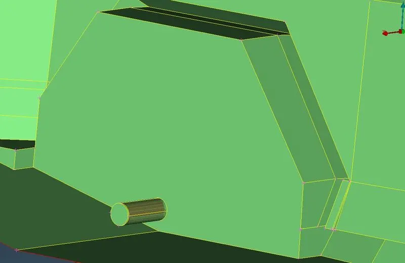
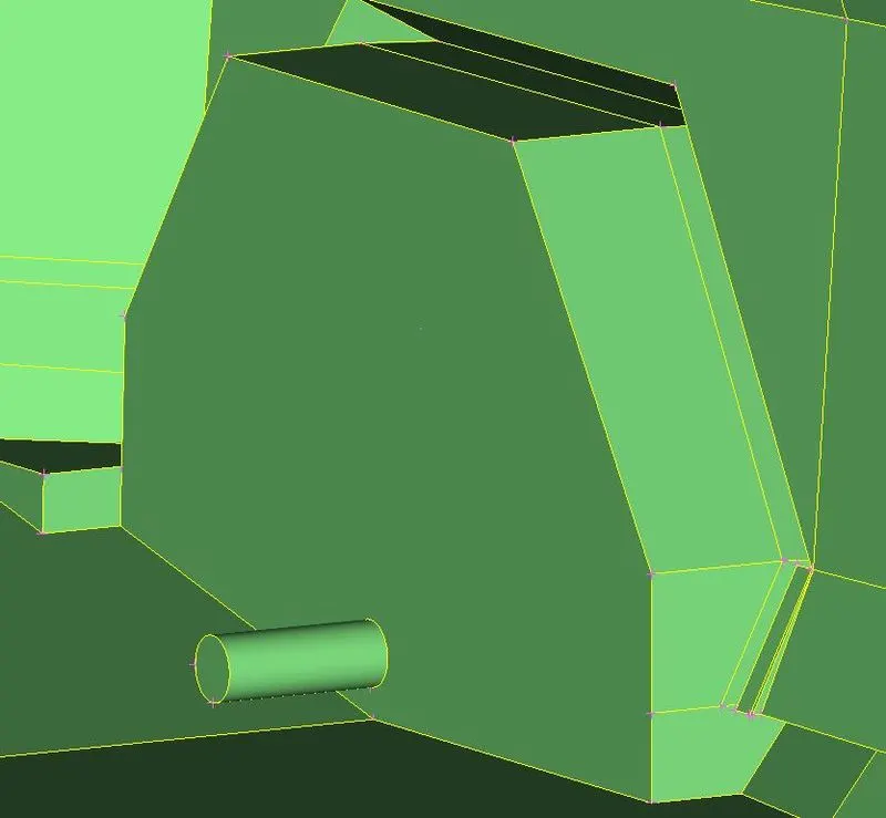
We proceed on to do various cleanup process over different surfaces and making sure there is no errors present as we move on to create mesh.
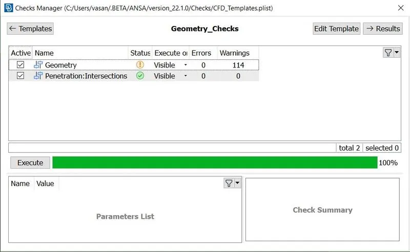
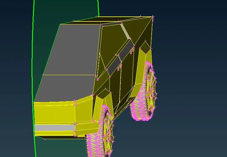
Tere ar no errors ,means we can proceed further. We are developig the model for external simulation problem. In real cases the down sized ot the real model would be brought to the wind tunnel testing facility to study the changes in temperature ,presssure and other properties and this process is expensive. In most conventional way and to reduce the cost this is replaced with CFD model. For this we have to creat an enclosure around the model so that that acts as a control volume and the properties can be studied inside it. First we have to define the PIDs so that it would be easy for us to define the target length individually. We can define them by isolating the required surfaces to be defined using AND tool and then creating new shell properties and naming into different part as per our convinent, then using apply option we select the isolated surfaces for that cerated Shell ID. this way we can creater the PIDs as below.
Defining PIDs
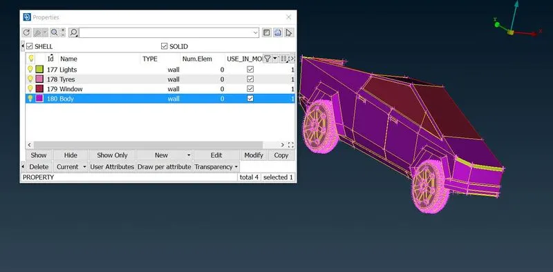
Now we have to define the quality criteria. We do thsi so that we can compare and ensure that the genarated mesh elemets are of good quality and will lead to the convergence of solution with no complications. Here we are only concerned about three qualities Skwness, maximum and minimum length of the elements. We define the max and min length with respect to the mesh target length size where the maximum limit for biggest target length will be the maximum length and the minimum limit for the smallest target length will be the minimum length.
Mesh Generation
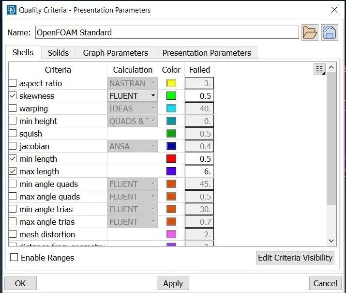
Then we select the show only option for the individual PIDs for mesh generation. So ,we first give a range for the paticular target length and mention in mesh properties. Then we choose,
Mesh classic > Perimeter > Spacing > Auto CFD > Macros& Perimeter> select The PIDs > Mesh Generation > CFD> visible.
This way the mesh is generated and before moving to next PIDs we must freeze this PID so that the further mesh creation with the adjusent parts will not affect this mesh. Macros ar the plane surafecs where as the Perimeter is the edges , thsi operation helps in dividing that entity for the mentioned target length.We repete the entire steps for each PIDs and create the mesh for all parts. The details of target length is given below,
Body - 4 mm (3 - 5 mm)
Tyres - 3 mm (1 - 3 mm)
Lights & Windows - 2 mm (2 - 4 mm)
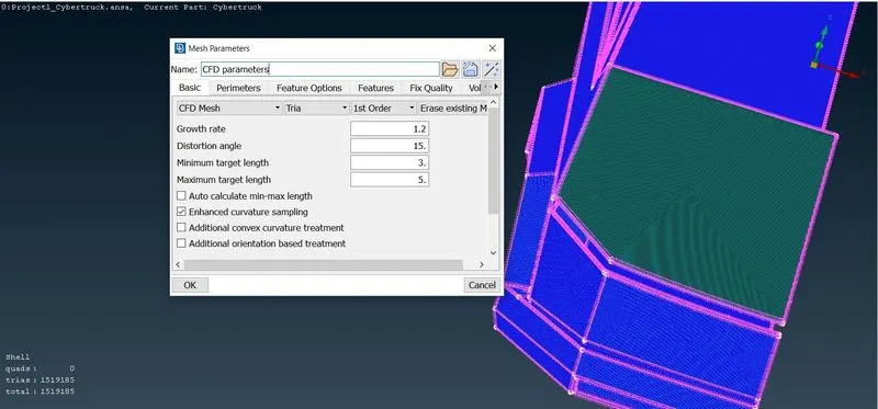
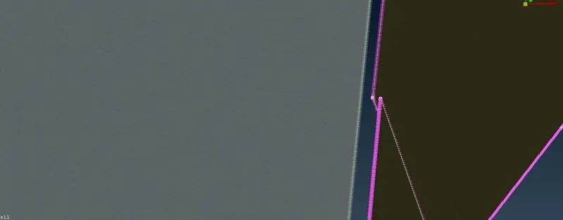
Since we have meshed all the PIDs we now have to check for off Elements or poor elements which does not meet quality criteria. First we have to unfreeze the entire geometry then the off elements can be solved by right clicking near it the pop up box will appear the we need to choose as follows,
Improve> Reconstruct> Edges > Ok this eliminates most of the off elements. This off elements are elements in mesh which is beyond our mentioned quality criteria. Some elements are to be corrected manually, for this we use the option move under grids. And we can drag the poor elements randomly acrosss all axis untill the error is vanished. Finally we have to have zero off elements.
Then we have to complete the model by genarating the other half. For that we use the transform option and selecting 3 points along the mid surface and then hitting finish will generate the complete Cyber truck.
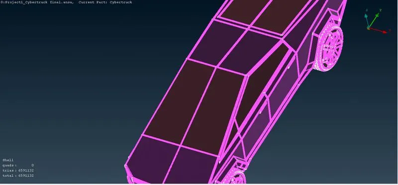
Creation Of Wind Tunnel
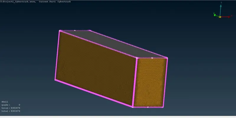
Now we have to create the enclosure around this , for that we ahave to create curves using points, which needs to be defined around the model. Initiall we measure the total length of the car from rear to front to be 6000 mm. For this we use the create points using relative and we choose the hot point at the bottom at a distance away from the surface,
Front : 4*6000
Rear : 6*6000
Top : 3*6000
Side & Bottom : Away from the nearest surface.
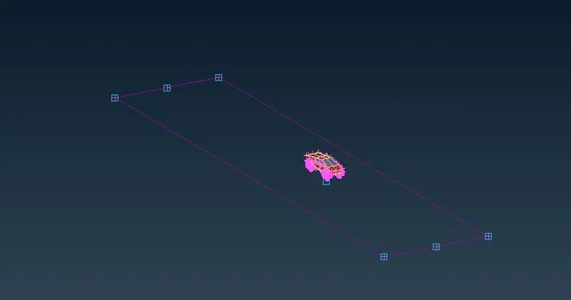
We create points using relative tool and with that we define the curves out of which we finally create a surface. For the top face we use offset tool to create a new surface at a distance from the existing surface.
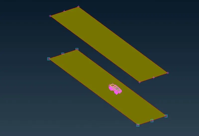
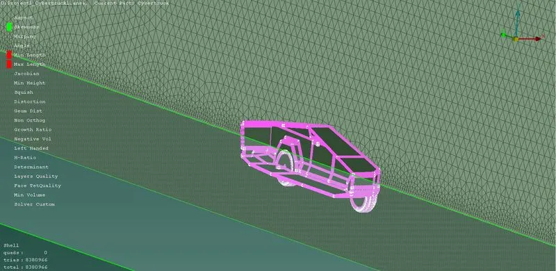
The we crate the whole enclosure using new face option. To generate the mesh we now us the same method and create PIDs, mesh using the previously gfollowed steps. Now we have to create the mesh at the side faces so that the mesh size increases from 100 to 300 as it moves close to top face, for this we use manual option under spacing.
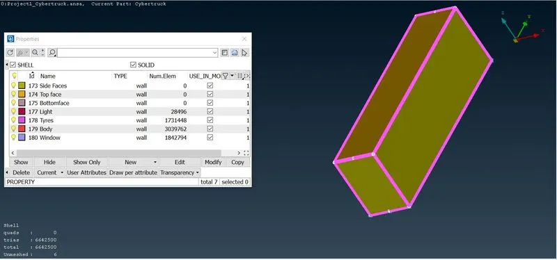
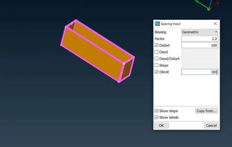
The off elements are cleared by implementing same method as above.This way the entire mesh is genarated for the body as well to the enclosure.
Learning Outcomes:
- Geometry clean-up of individual PIDs
- Setting different target length for each PIDs
- Introducing quality criteria for mesh
- Eliminating Off elemements Manually
- Creating Wind tunnel
- Genarating mesh of varying length over single surface.
Conclusion:
In this way the tria elements are created over the surface of the mody and as well as on the enclosure (wind tunnel). The volumetric mesh is not generated because it requires high computational power and time. Thus generation of surface mesh is understood with the addition of quality criteria.
Model : https://drive.google.com/file/d/1R64Sj4arKvsrll3sP37AM2nFwXkiLf83/view?usp=sharing