Project 1 : CFD Meshing for Tesla Cyber Truck
Tesla Cyber Truck
Aim
To do an external flow analysis of a Tesla cyber truck, we need to create a volumetric mesh of the tunnel with the given model.
Procedure
The Wind tunnel volumetric mesh has been created with the surface mesh of the given model and wind tunnel. Initially, we need to check the geometric clearance of the model and do a parametric input to do a surface mesh of the model and tunnel. But the process after surface mesh will take a lot of time also the system that I have with the low-end processor did not support the process of Meshing Wind tunnel volume .so I stopped the process up to surface mesh generation.
The step-by-step process of creating the mesh is as follows.
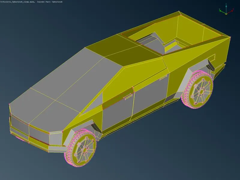
Step 1:Initially, the model (Tesla cyber truck) was imported into ANSA and the geometry was observed from all sides to visually inspect the model.
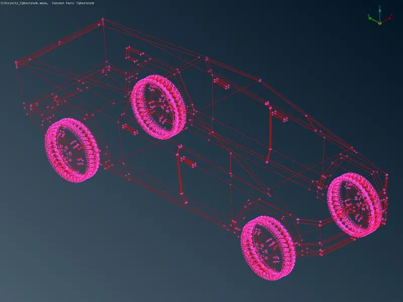
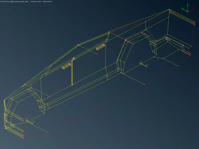
Hear the imported model has shows completely single cones, it may be released cones to avoid it do a Topo once to clear the single cones.
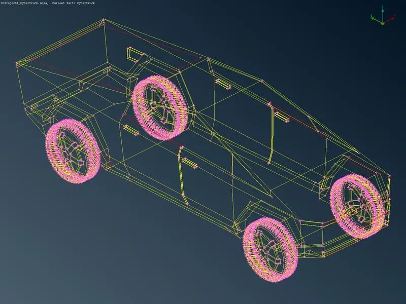
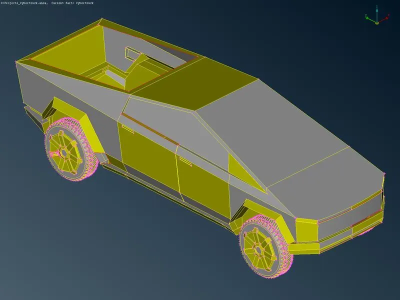
The above image shows most of the red cones gone with the one TOPO.
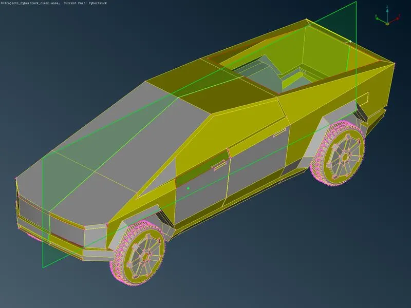
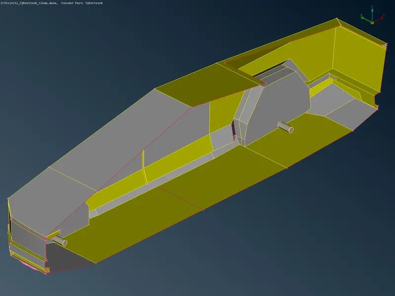
Step 2:The model is axisymmetric, so we can create a mesh to half of the part and mirror it on the other side .so use the plane cut option to create a cut in the middle of the car and delete one side of the car.
Step 3: Geometric check
With the half-symmetric part of the car, we go for the geometric check to find the topological errors in the model.
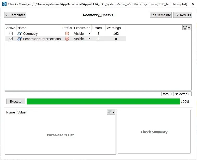
The model has some geometric and intersection errors also we need to verify the warnings and make sure it will not cause any errors. The errors shown are resolved one by one in this process.
- Geometric errors
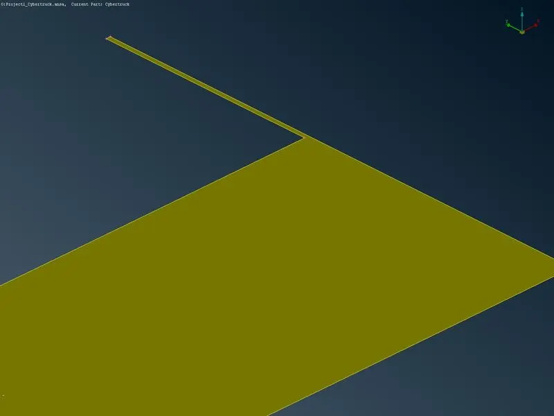
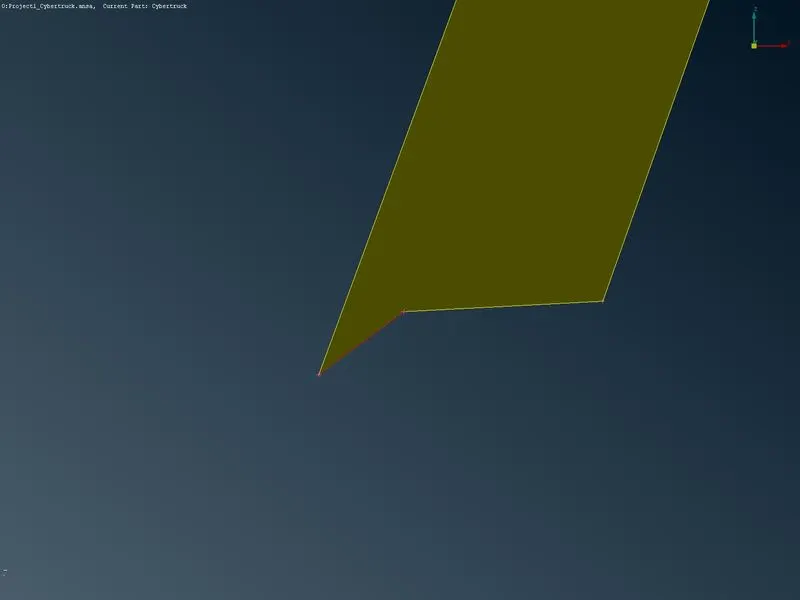
In this model the geometric error shows are crack between the cones, it can be resolved by past cones are we can make a new surface on it.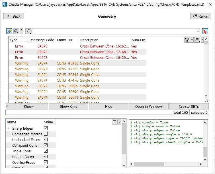
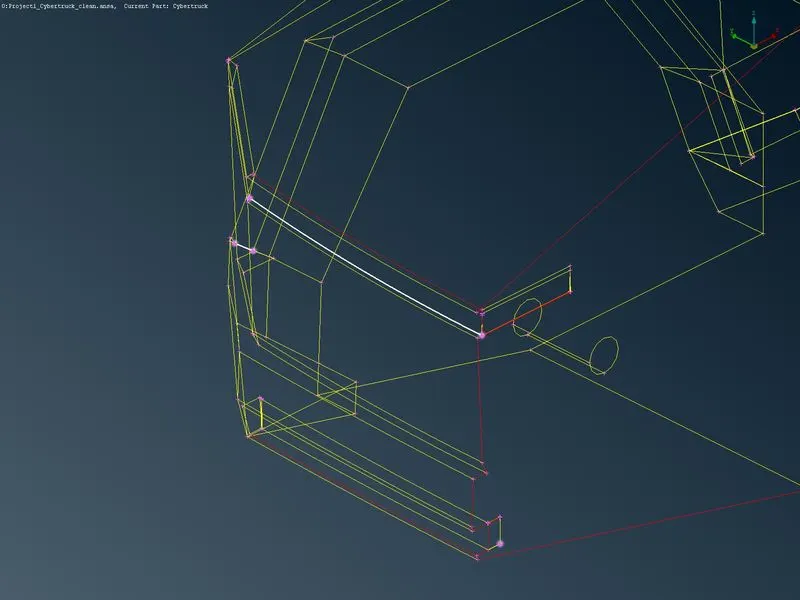
the errors are showing the front part of the cars and the warnings are single, concave, convex, and mixed cones. - Penetration error
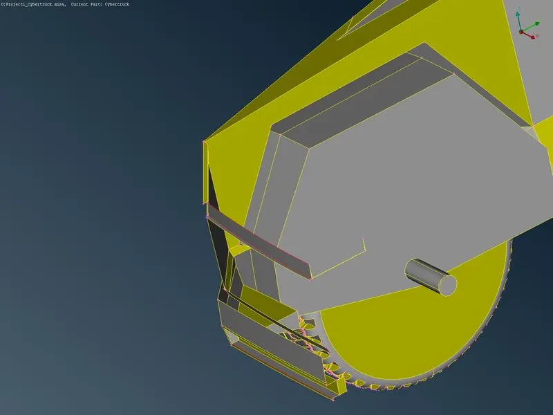
The intersection error shows in the grill part and tire region of the model shown below.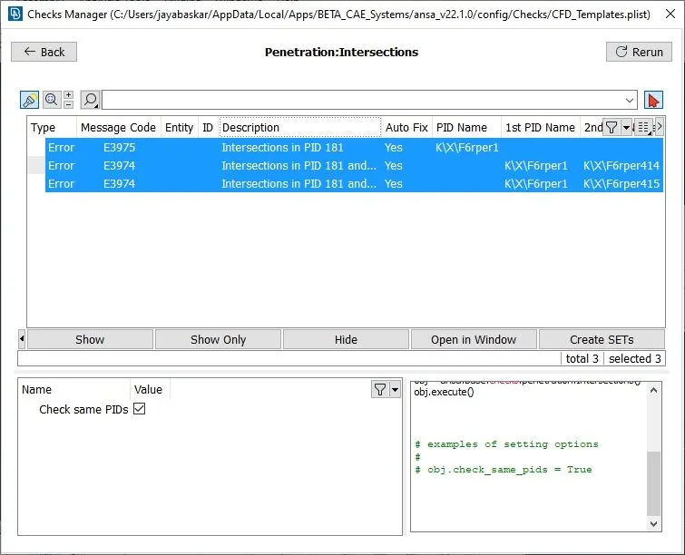
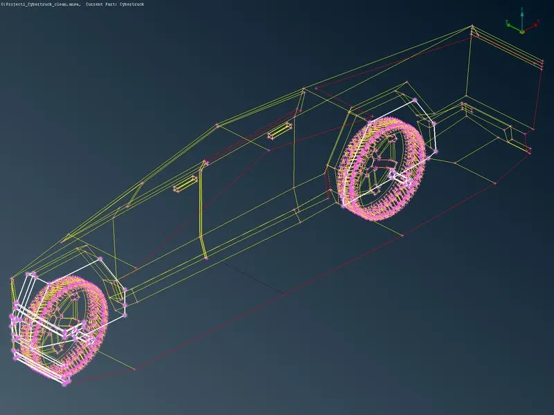
step 4:Topological clean-up
The found errors are checked visually and cleared with the help of the TOPO deck. Initially, started with geometric mistakes and then go for the intersection error one by one.
The images after geometric clean-up are shown below.
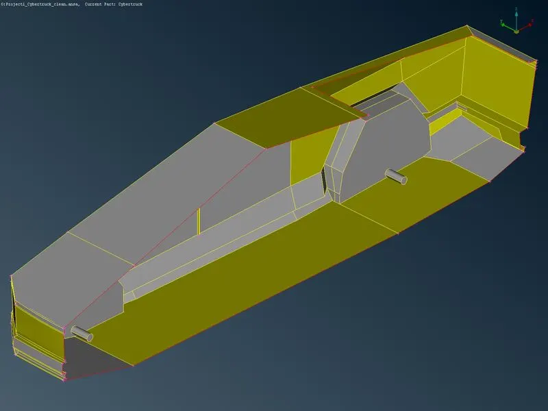
I used to remove some sharp edges and small overlapping surfaces because those sharp edges may give minimum target length while meshing.
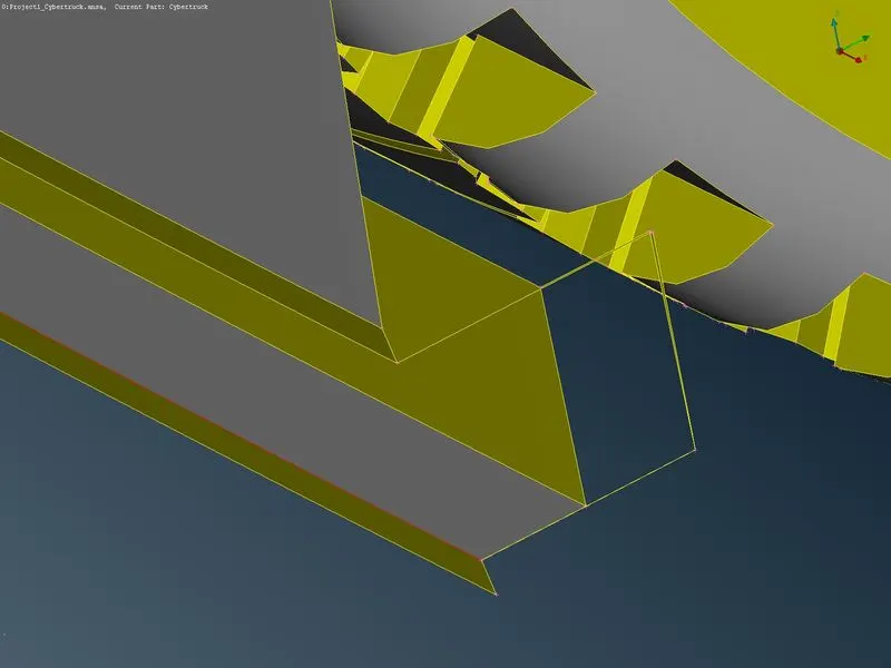
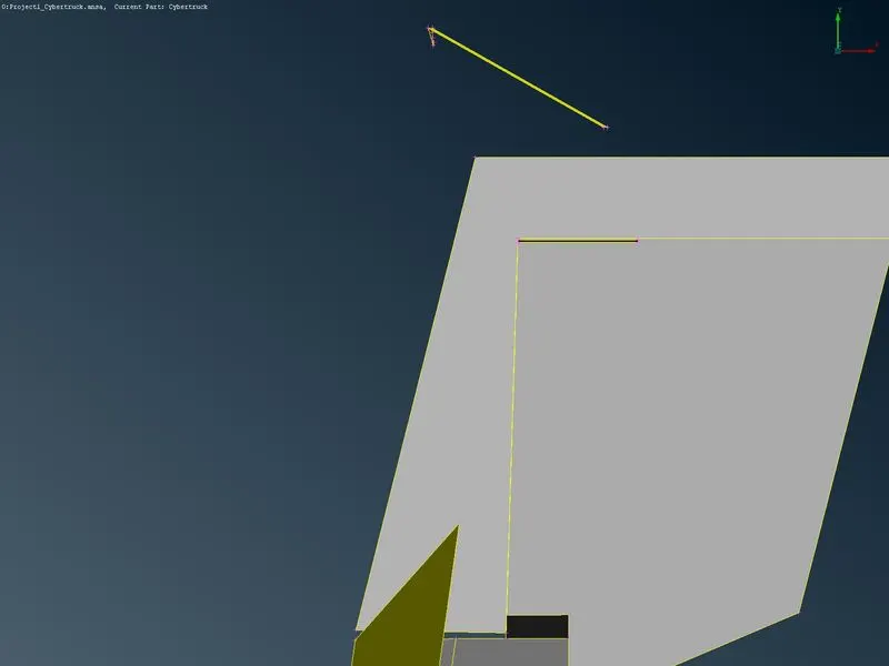
After cleaning the geometric error, we do the geometric check to verify
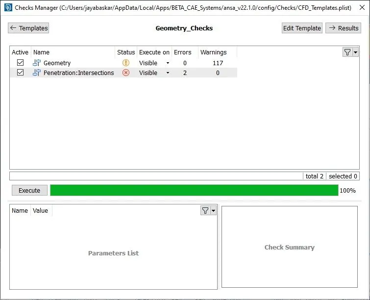
The check manager shows the geometric error will be zero and warnings are 117, by cleaning the geometric error itself one intersection error is gone, and we have two more intersection errors that cause in between tire and body
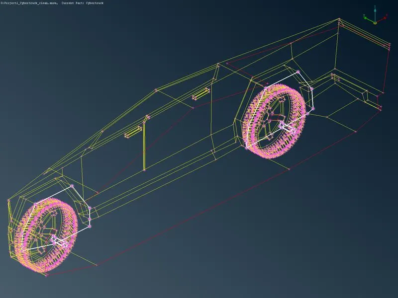
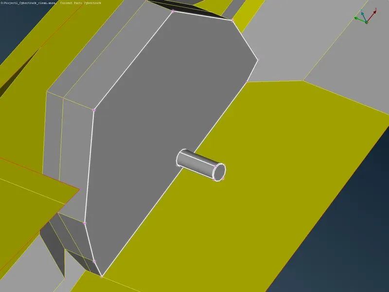
Images after cleaning intersection errors and check manager are shown below.
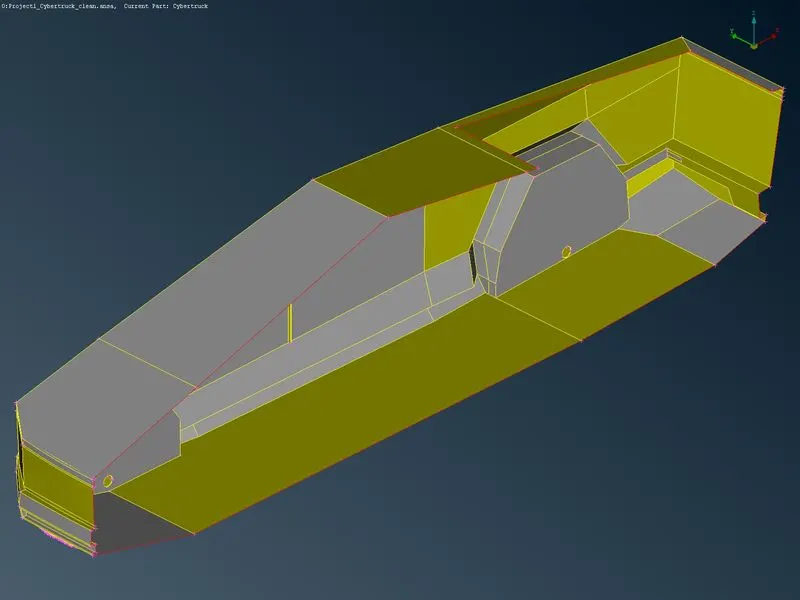
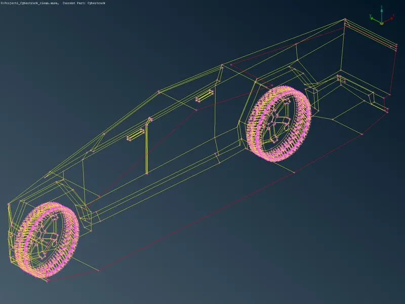
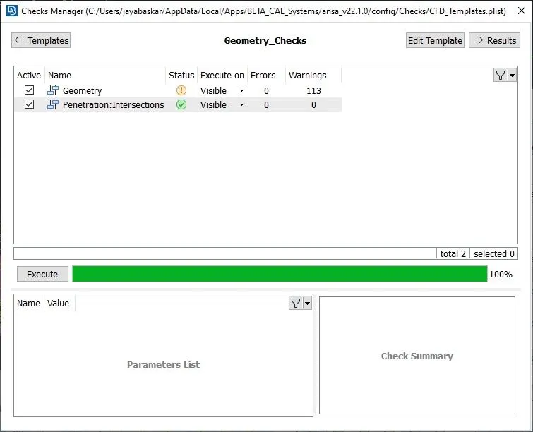
Now the mode is ready to create mesh without any error
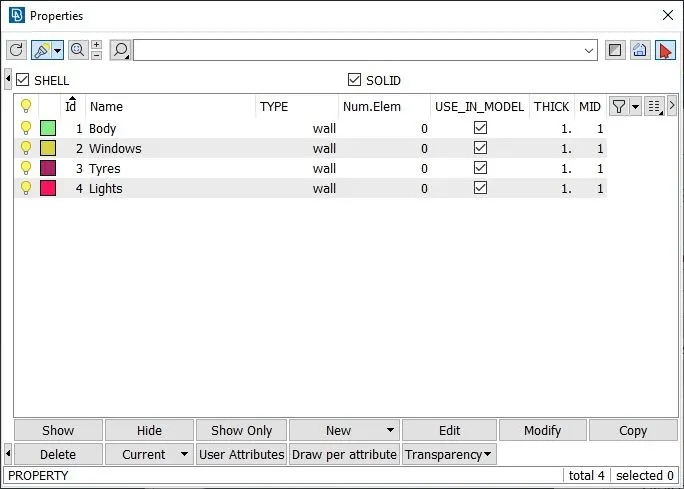
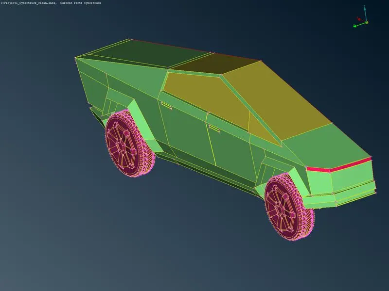
step 5:Applying PID
Before starting the mesh, apply PID for the different parts separately to get easy access to the parts.
step 6:Mesh generation of half of the car
The target length of the different parts are
- Body:4 mm
- Windows:3 mm
- Tyres:3 mm
- Lights:4 mm
The target length of the different parts is applied with the spacing `->` CFD auto.
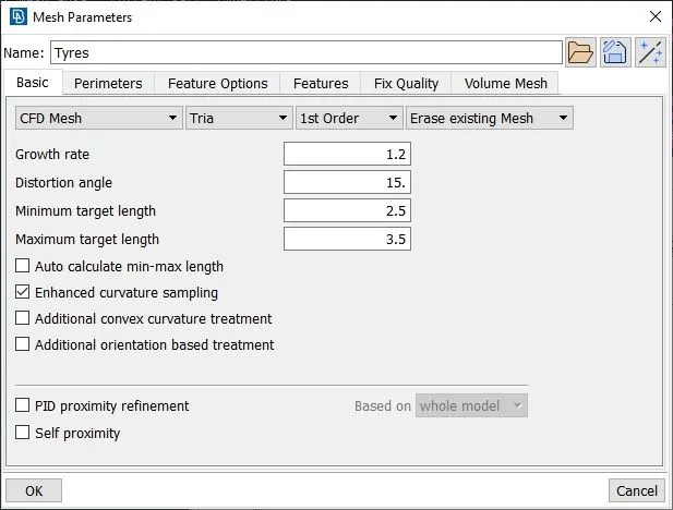
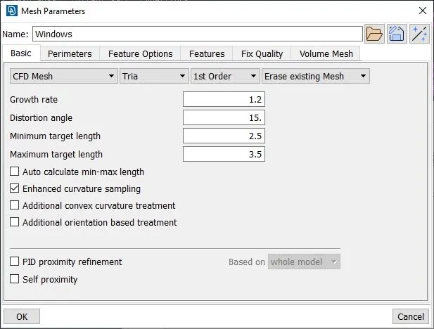
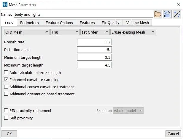
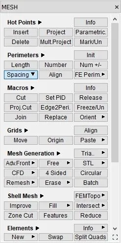
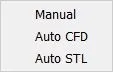
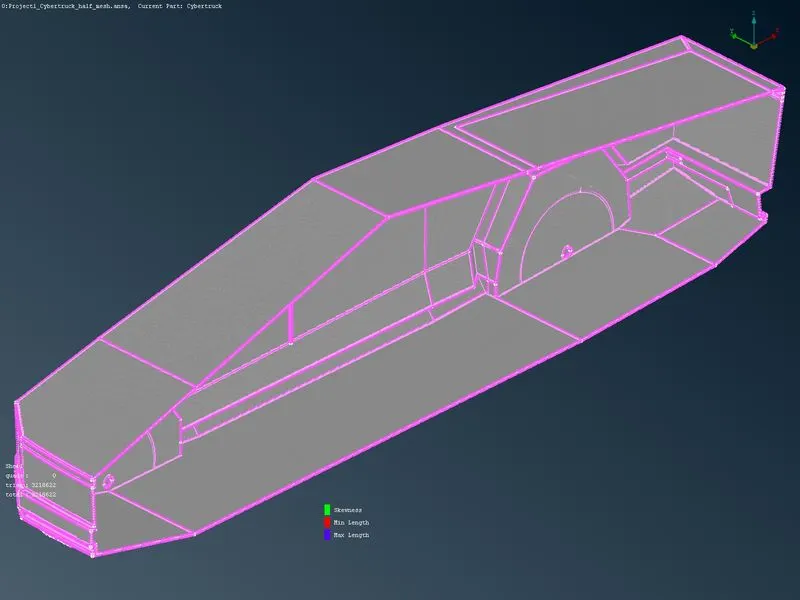
After substituting the mesh parameters, we use CFD mesh to mesh the car and the images are shown below.
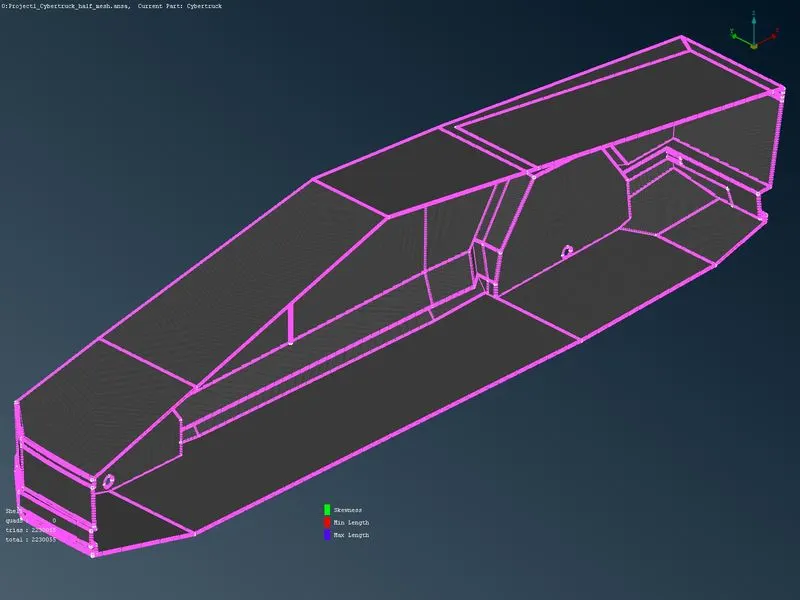
`strong>Quality criteria: The quality of the mesh has been maintained in between the range of minimum target length of 0.1, maximum target length of 7 mm and skewness has been maintained at 0.5.with these criteria the off-elements are resolved with improved options, as well as some of the off-elements, are cleared manually`
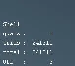
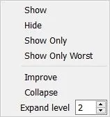

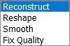
The above-shown pictures are pop-ups to solve the off-elements.
Step6:In this step, half of the car will be mirrored to another half of the car using transform`->` copy`->`select all the entities`->`symmetric`->`Mirror 3 point plane after that, select three points that seem like it will mirror properly.
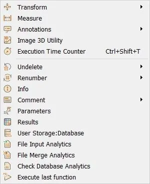

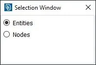
By following select all the entities and do a middle click, it will open a copy entities window.
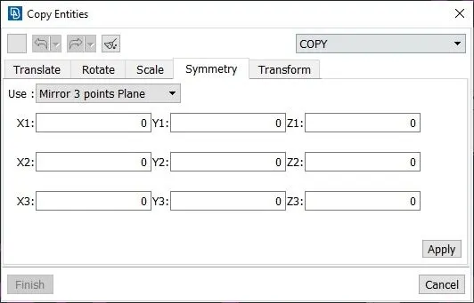
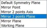
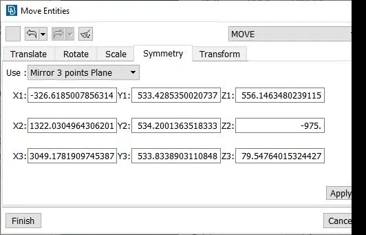
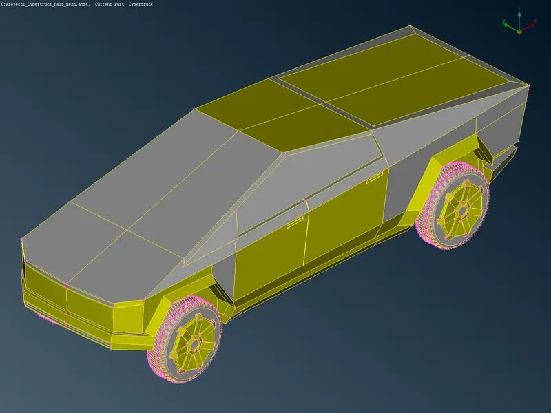
After completing this step, we need to check if any single cones are present in the model and need to clear it to get a clear mesh. This model gives a red cone in the front parts and other areas are mirrored properly.
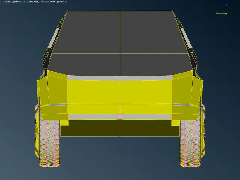
The image after cleaning the shown single cones shown below.
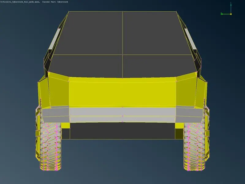
step 7:Full body mesh
When we do a mirror option it automatically mirrors the mesh of those parts and some parts get unmeshed due to the red cones during cones mesh, these are again meshed using CFD mesh and after freezing the entire model to maintain the model as it is.
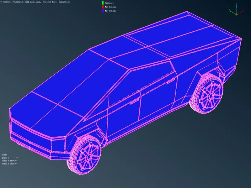
Step 8: Tunnel Creation
The tunnel has to be created with the standard to maintain proper flow analysis after meshing.
X will be the total length of the car we get 5690.247 approximately take `x~~5700` hear.
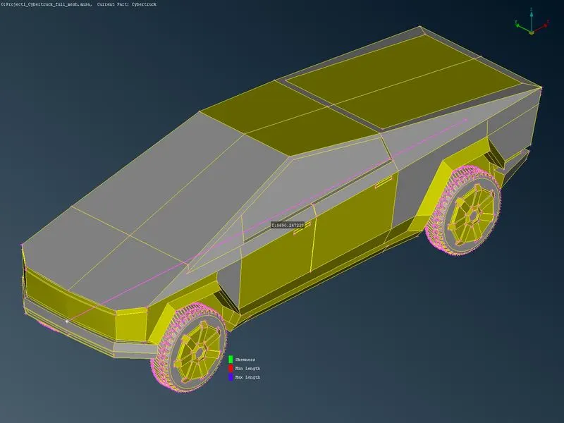
The conditions to create the tunnel
- the tunnel from the front face should be 4x distance
- the tunnel from the back face should be 6x distance
- the tunnel from the side face should be x distance (Both sides)
- the tunnel from the top face should be 3x distance
- the bottom face has not been considered because the flow analysis majorly concentrates on the top surfaces, so we can create the bottom face at the distance that we choose
With these conditions, the tunnel has been created by creating points (Topo`->`points`->`relative) it will create a point relative to a selected point, so we can create it from the hot points presented on the surface. With this hot point, we can create curves the curves have been used to create wind tunnel surfaces.
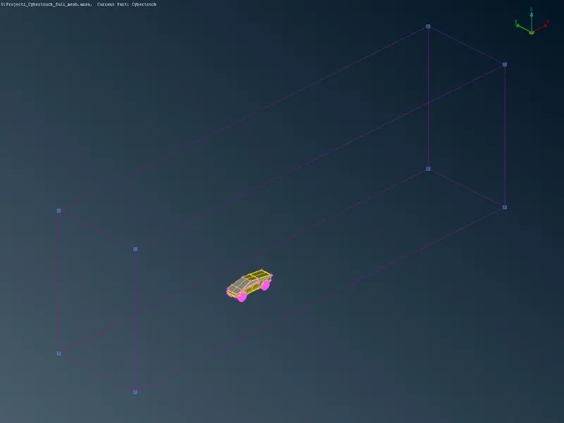
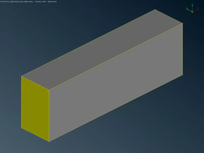
step 9:Tunnel mesh
After completing the tunnel building we start mesh by applying the tunnel spacing here we use two ways of spacing, the first one is auto CFD which is used for the top and bottom space another method is manual spacing applied for all the side surfaces of the tunnel.
Here I used 300 for the bottom and 500 for the top surface because the meshing of the wind tunnel will require a dedicated processing system, so I used maximum value for creating the mesh.
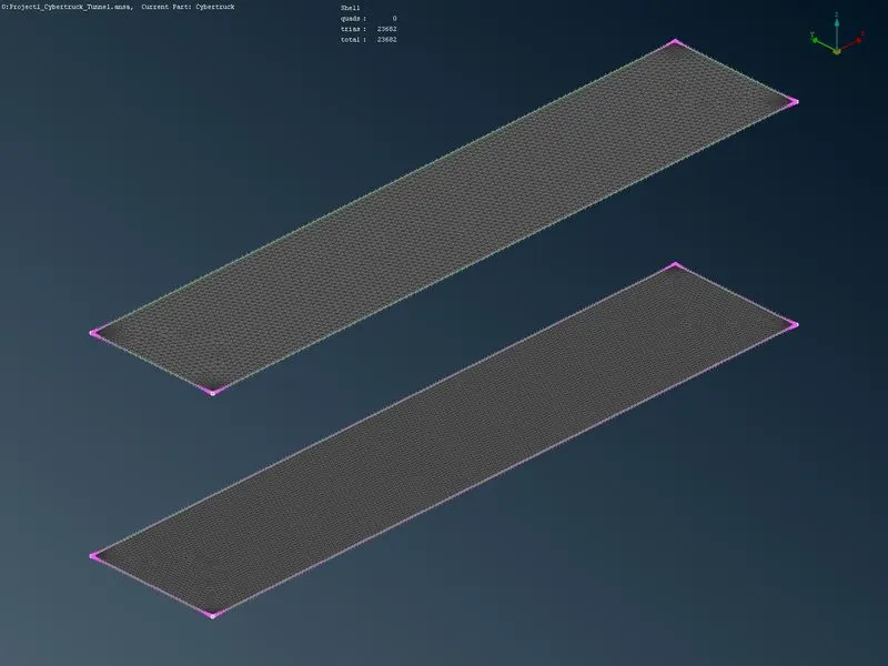
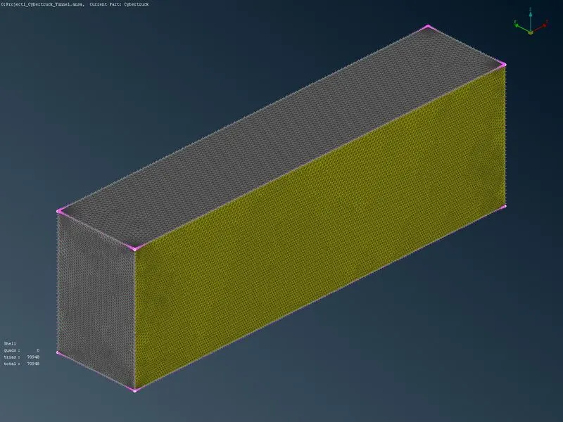
For the tunnel side faces, I used spot mesh because my system did not support the CFD mesh generation to do, and all other parts have meshed with CFD mesh.
The tunnel mesh has been shown above for a more clear view of the model I use to cut the plane to show the internal parts.
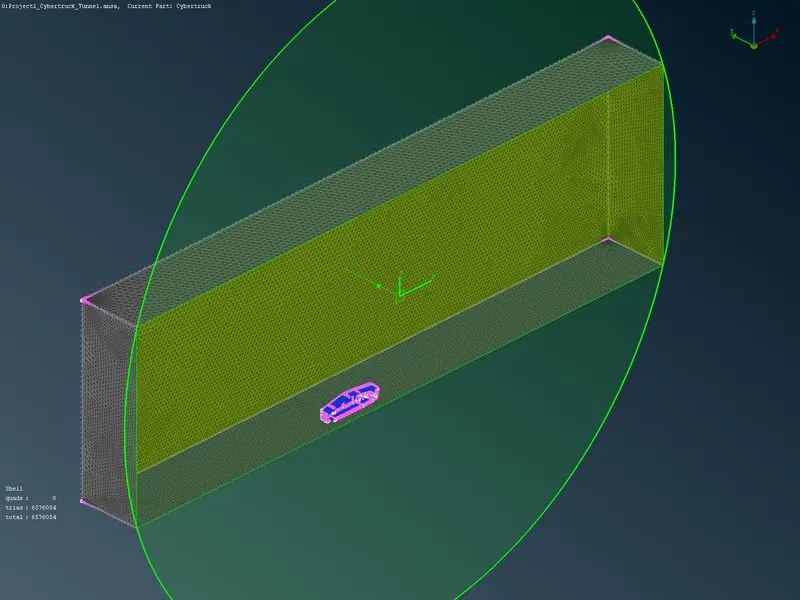
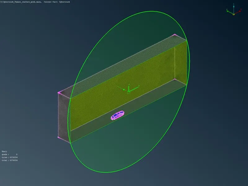
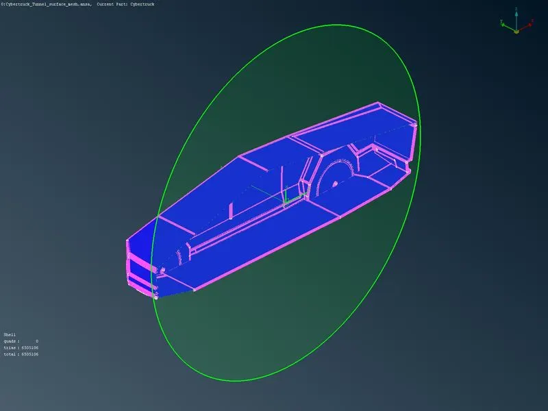
Meshing Wind tunnel volume with tetra elements may take a long time, so the surface mesh has been submitted, and the mesh parameter files are attaching with the submission.
Conclusion
- The surface mesh of the given model and wind tunnel has been developed with tetra elements, and it contains a total of 6576054 surface mesh elements present in the obtained mesh.
- It will be clear that creating fine mesh requires dedicated systems.
- A decrease in target length increases the mesh elements, and an increase in target length decreases the mesh elements.
Link for the uploaded Google Drive file.
https://drive.google.com/file/d/19-LsoS8m28BttCmWmMJaZXUeCWM5e2HE/view?usp=sharing
Other files such as mesh parameters and quality criteria are attached with the report.