Project 1
1. Aim :-
Here we have an model of Ahmedabad metro rail bridge. Here we calculate dead load on bridge after that According to IRS loading calculate live load due to metro coach and also effect due to Earth pressure as well as Wind load according to IS code 875 part -III and Sesmic load on Bridge.
2.Introduction :-
As here in the task Model already created so here we need only calculate the different load effect like effect of dead load on bridge as well as due to live load ,wind load ,earth pressure and sesmic loading.
3.Given Data:-
1.Unit weigth of soil - 18Kn/m2
2.Location -Ahmedabad
3.Sesmic zone (As per IS 1893)-III
4.Basic wind speed (As per IS 875)- 47 m/s
Now for given data we calculate the desire loading.
4.Procedure :-
1. Calculate the dead load due to self weight of bridge
2.As here model of Bridge is given so we will start from loading section
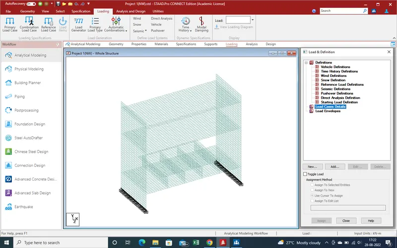
3. Go to "load case details as show in given below pic
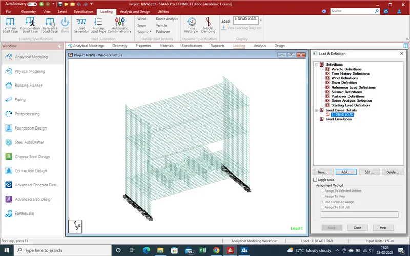
4.Add Dead Load as new case of loading .
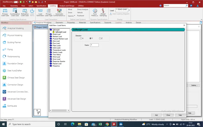
5.Add new case of dead load ,a new window has been open as showing given in below pic
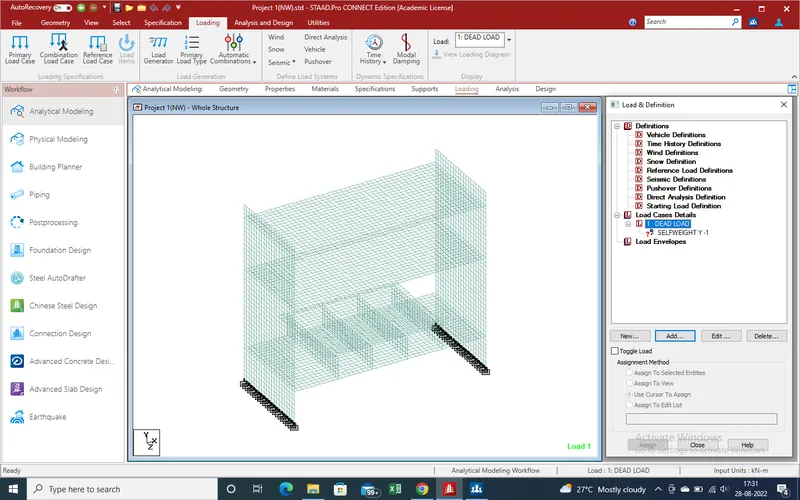
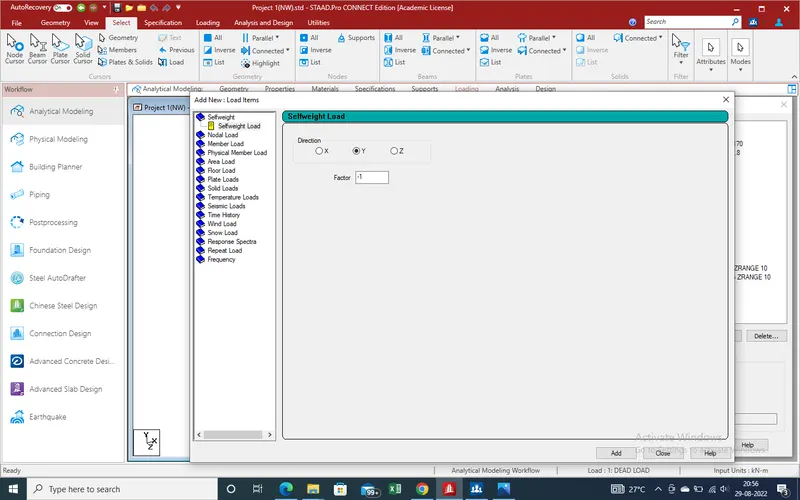
5.Click on "add" self weight factor shall be added to self fector , which will see as like in given below pic.
6.Now need the select the materials/componet which dead load we want to consider as dead load . Go to Select section select the "Plate ".
select the all plate as showing in given below pic
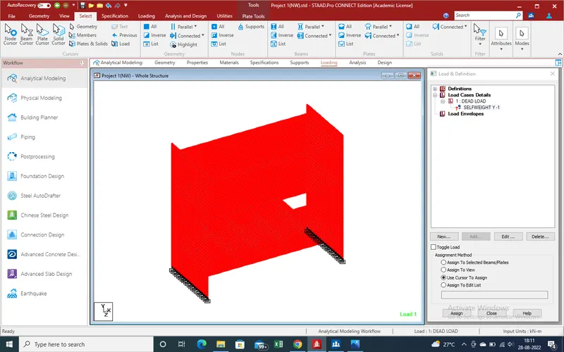
7.Now go to loading section "Select the plate /Beam for assign and click on assign
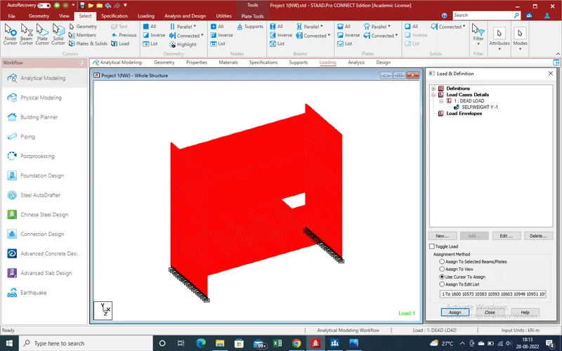
8.Dead load due to plate has been considered .Now need the dead load due to beam consider and follow same as pervious section
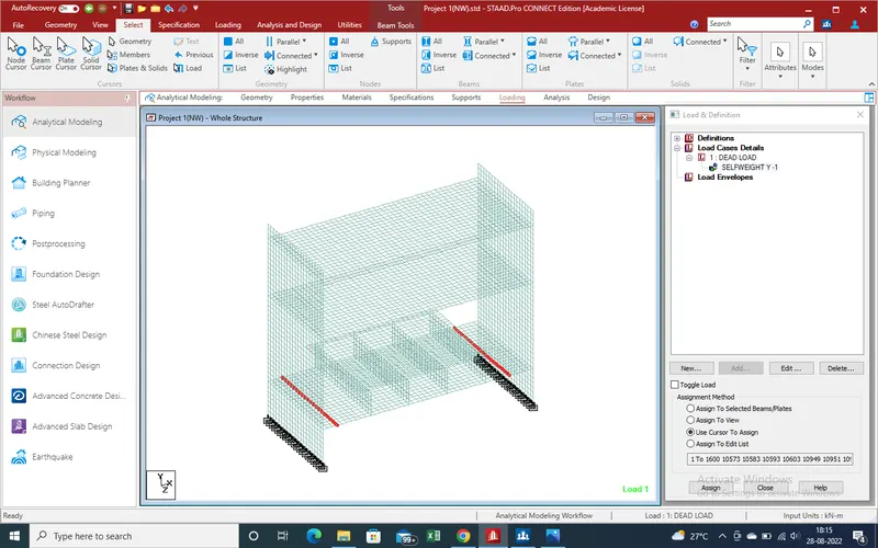
9.Assign
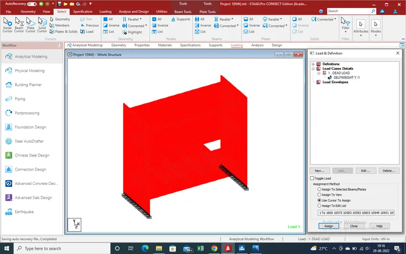
10. Dead load work has been done .Now go to IRS Loading due to metro .
11.Go to Defination Section of Loading
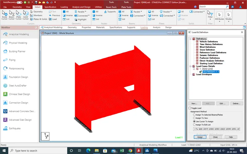
12.Select the vechile defination - Add . A new window has been opened as showing in given pic.
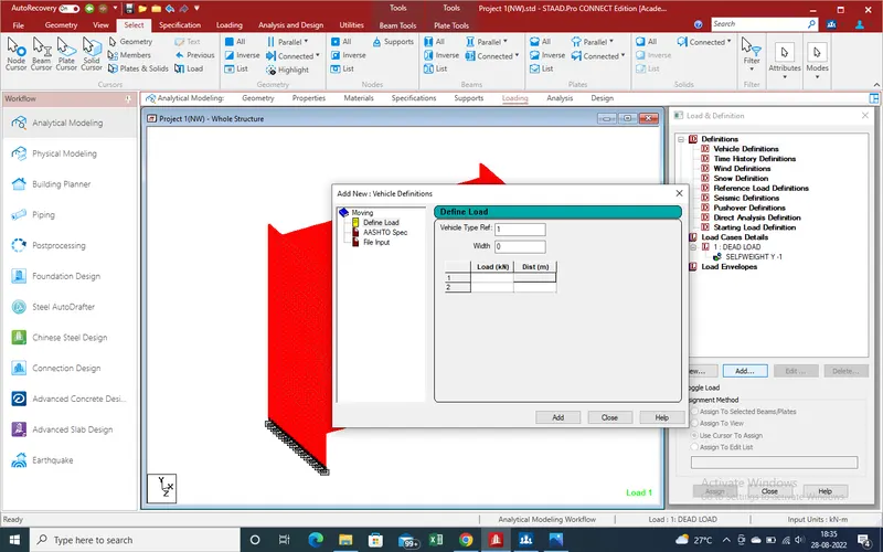
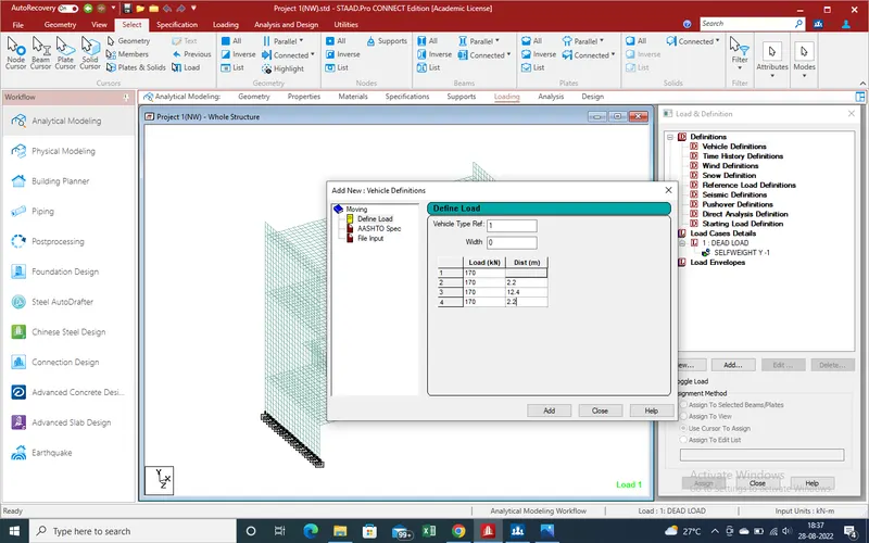
13.Put the load values and its distance as per IRS Loading
14.Loading case -Add new case
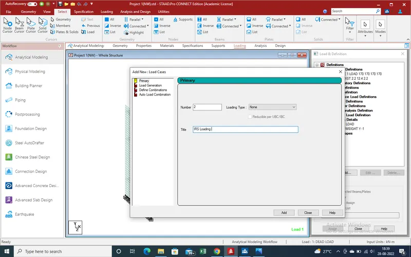
15.Add and close the window
16.Loading case has been add .Now need apply at required distance and position so again add
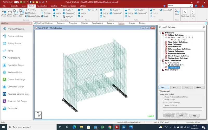
17.Create the moding load no as here we create 50 nos so put the values as 50
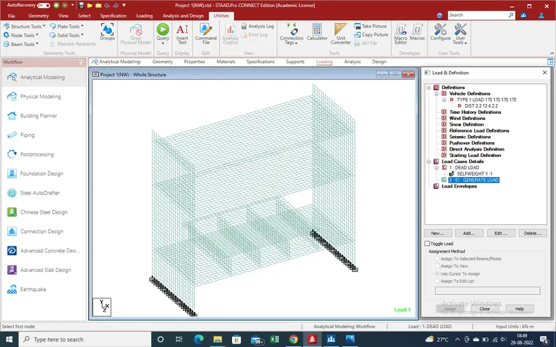
18.Again Select load genrate load and click on "add" for put the distance and interval and range also
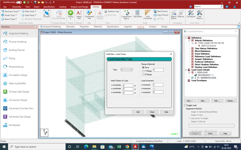
19. A new window has been open , put the values as
type -01
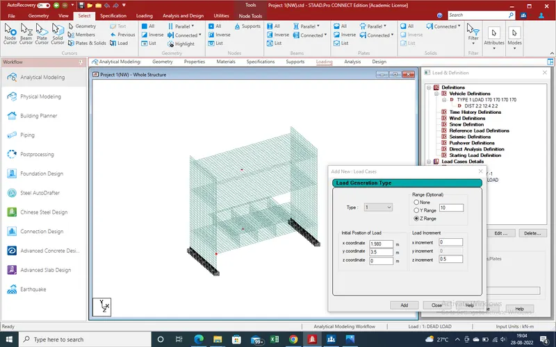
20. Another Side Loading
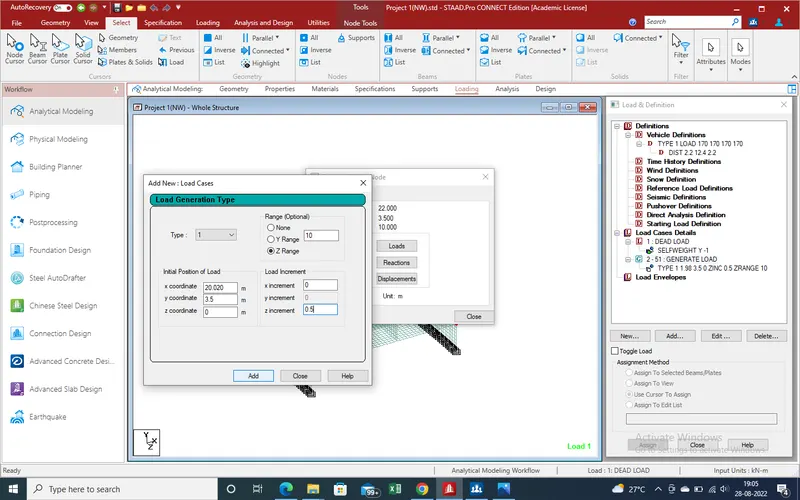
21.Now live loading work has been complited . Now create the earth pressure loading apply to model
22.As here model bridge is under ground so earth pressure will apply whole wall portion of bridge.
23.Here we have that soil unit weight is 18 kn/m3
so total load due to soil at bottom in rest
-18*20=360kn/m3
24.As here load in volume but we apply in Kn/m2 so in unit lenght lenght in height consideration
=360 kn/m2
25. Load from earth pressure has been calculate no need to apply this load on this model.
26.Go to loading section-Load case details -New
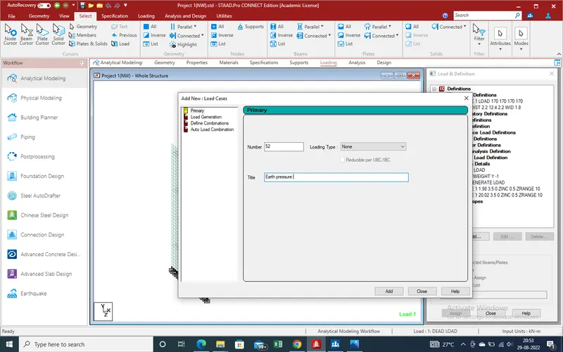
27.Select the Earth pressure and add "Add" Section and a new window has been open as showing in given
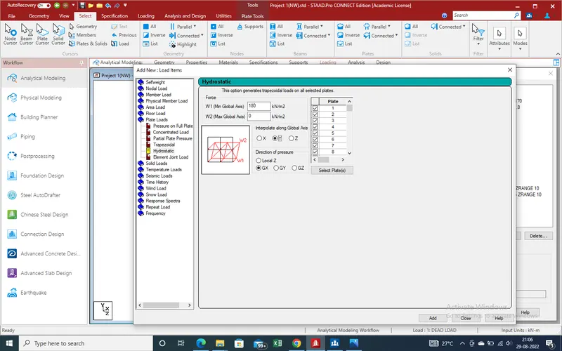
28.As earth pressure working as hydrostatic pressure on the plates so go to plate Load .After that select Hydrostatic section .A new window has been open at main window .
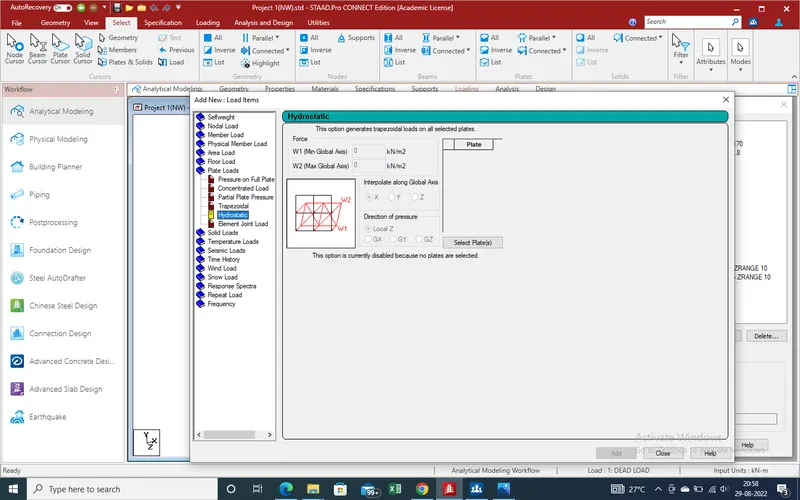
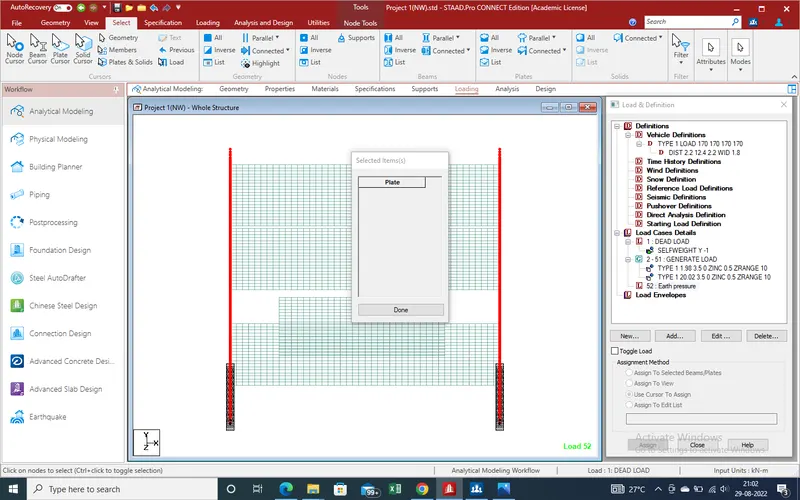
29.Select the plates where we need apply the load .
30.Apply the load value for minimum and max value.
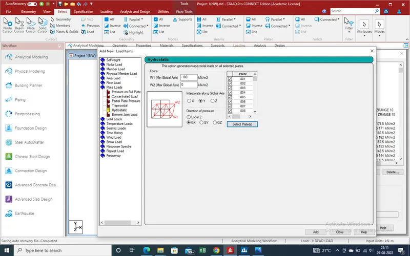
31.Now Apply from another Side (-) X-Direction
32.As here bridge in under Ground so there is no need to Calculate Wind load .
34.Now we calculate Sesmic Load
35.Go to Loading -Defination -Seismic defination
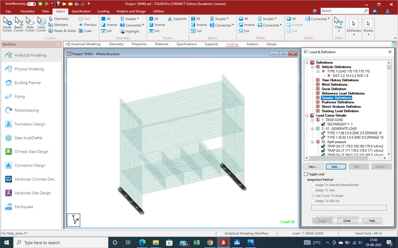
36.Click on "add" an new window has been open as showing given pic
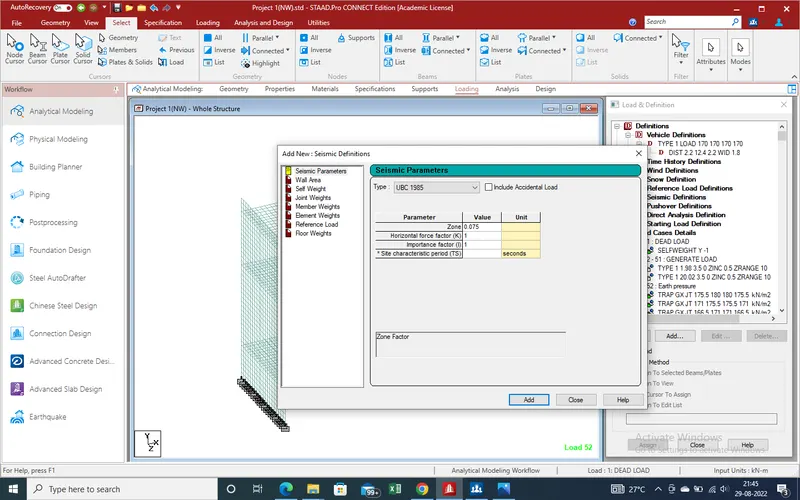
37.Select the latest Is code code
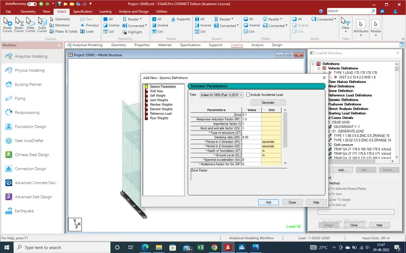
38 .Click on "Add" for next step .A new wind open now here select the self weight factor is 1 and add and close the window .
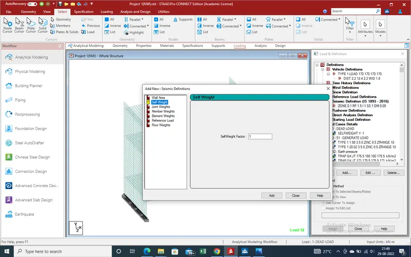
39.Now Add New load case section after add in defination section
I.Add for new load case
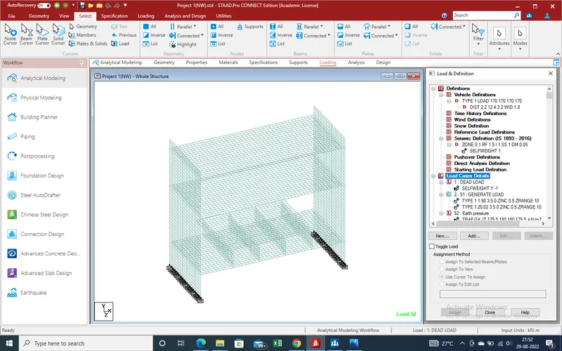
II.X-Direction
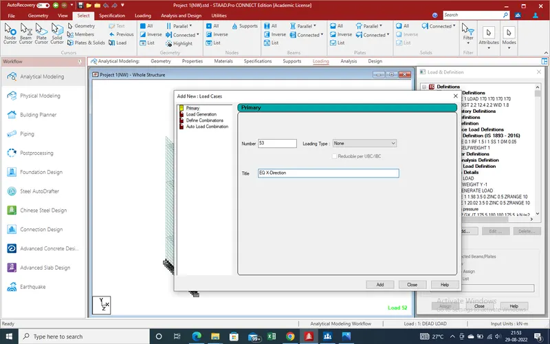
III.Same as for Y-Direction and Same for Z-direction
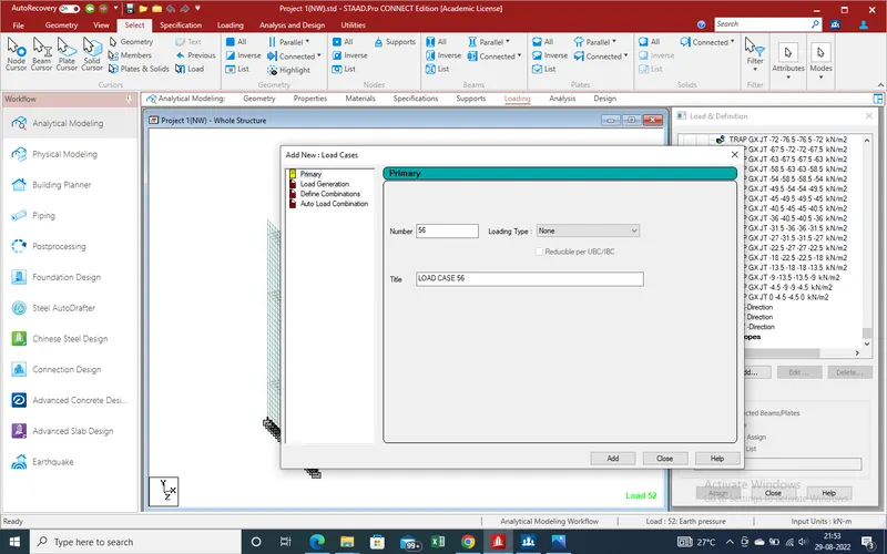
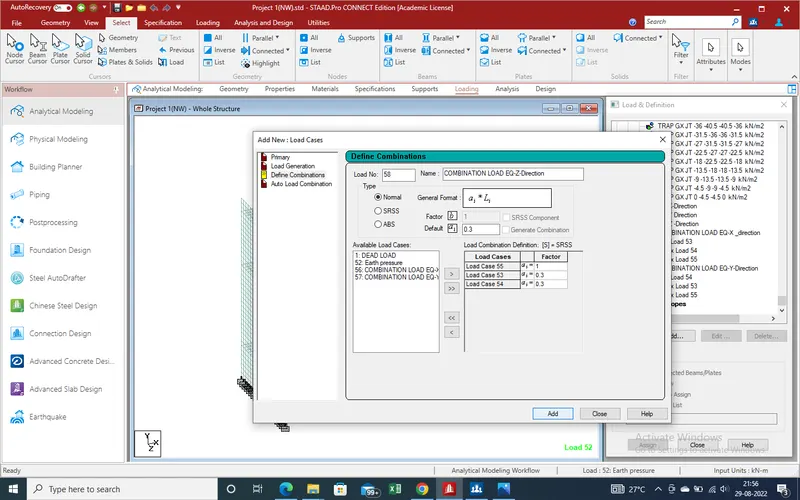
IV.Define load combination for X,Y and Z-direction
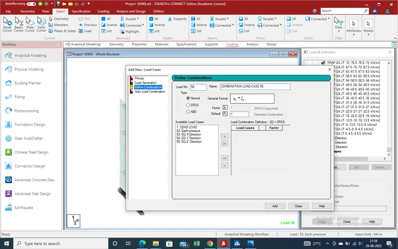
V. Master X-Direction
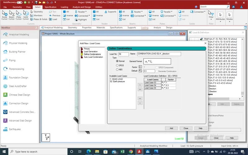
VI.Master Y-Direction
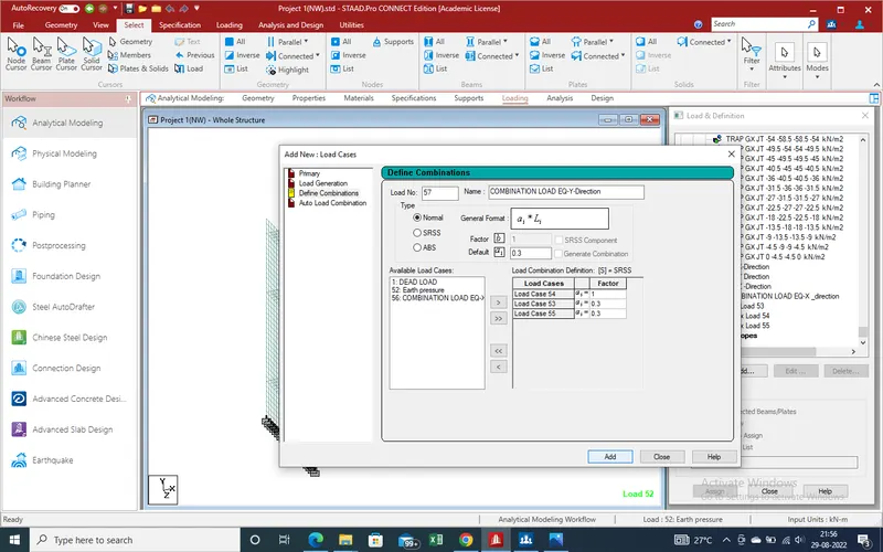
VII.Master Z-Direction
40.Select the load case and Click on "Add" a new window has been open as showing in given below pic.
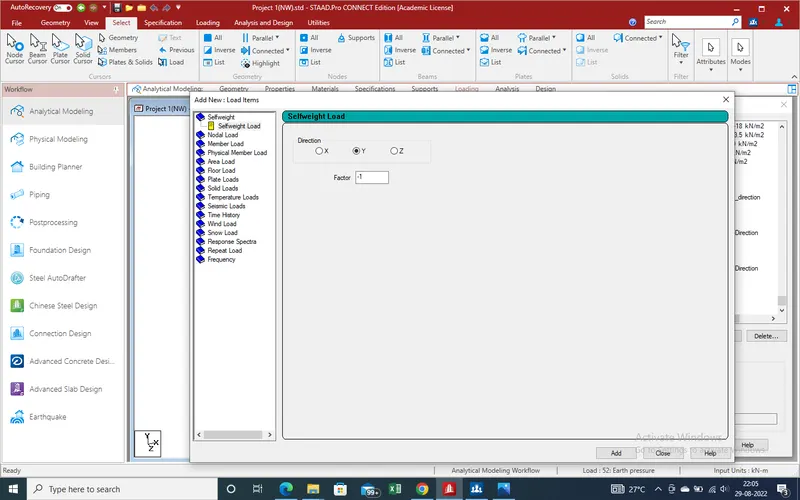
41. Select the seismic loads
a new window has been open
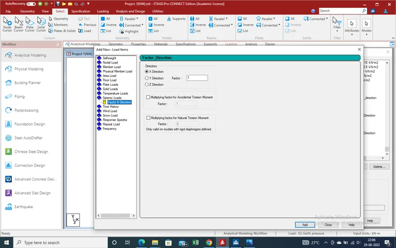
42.As load case for X-direction so select the X-Direction and click on "Add".
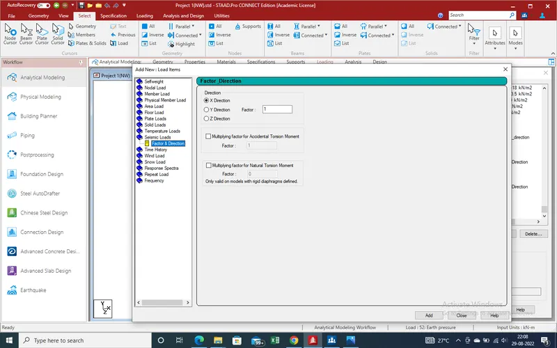
43.Same thing will done for Y and Z- Direction
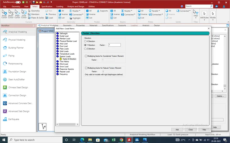
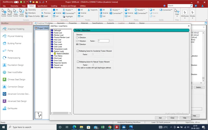
44.Now all loading has been Done . Now we Apply the run analysis
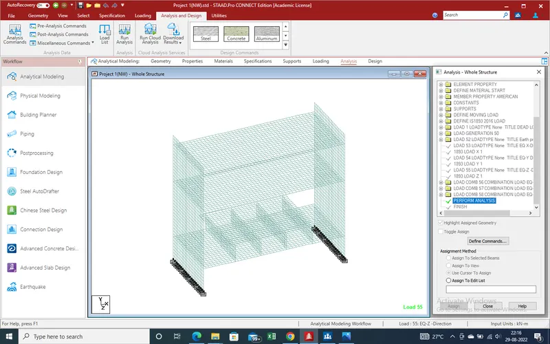
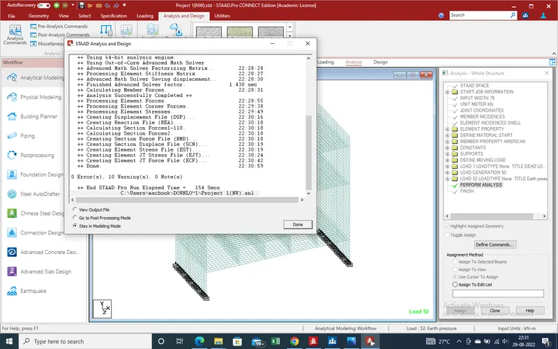
45.There is no error so go to Postprocessing mode for find displacement,shear force and bending moment.
5.Results :-
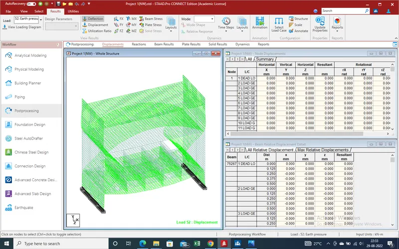
1.Diflection due to Earth pressure
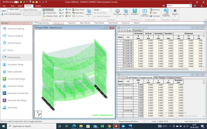
2.Deflection Due to Dead Load
3.Earth Pressure Loading Diagram
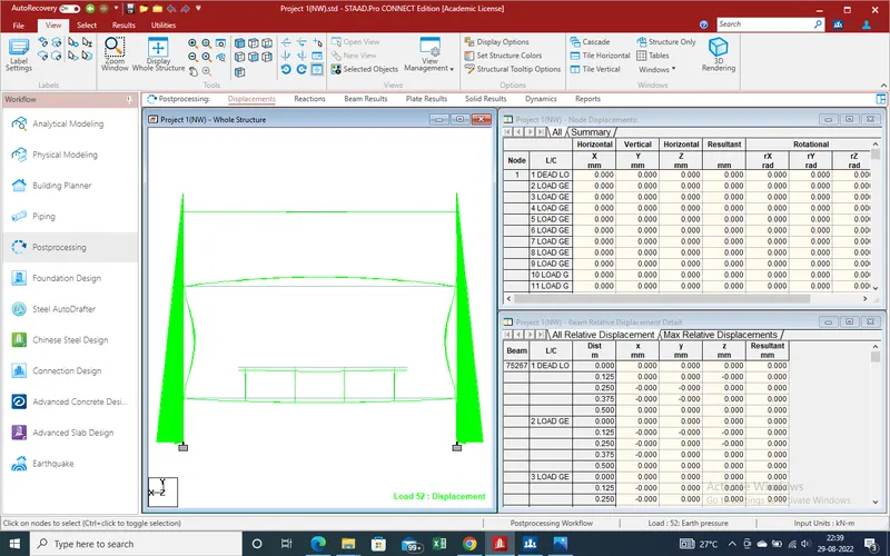
4.Deflection due to sesmic load in X-Direction
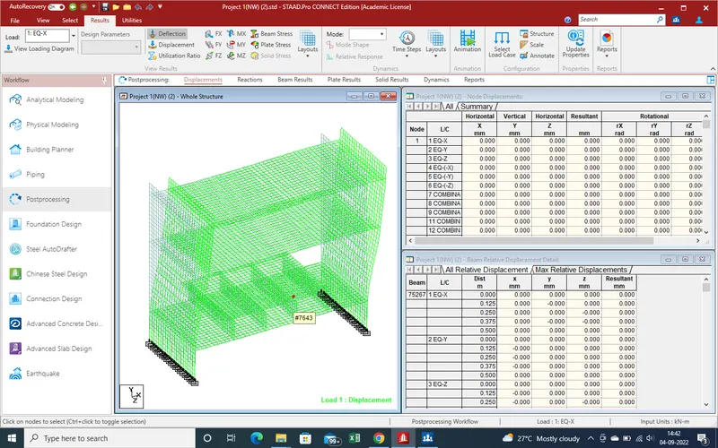
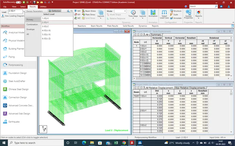
5.Same due to Y-Direction
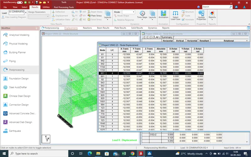
6.Displacement due to node displacement
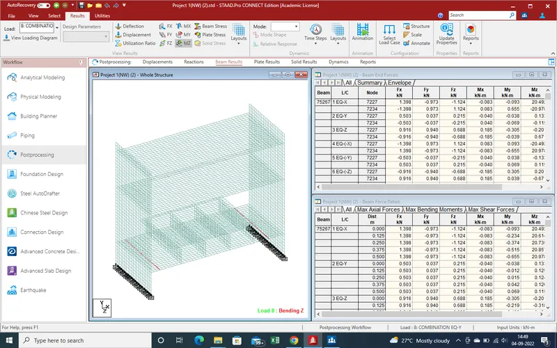
7.Beam Results
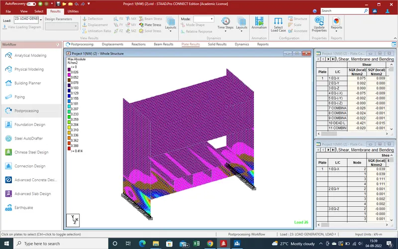
8. Plate Results
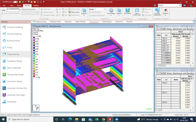
9.Deflectio due to Dead load /Self weigth
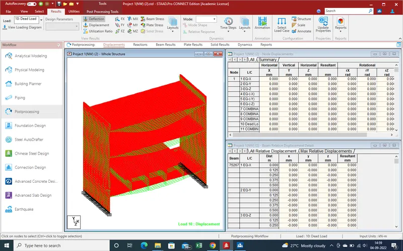
10.Plates Reaction due to Dead Load
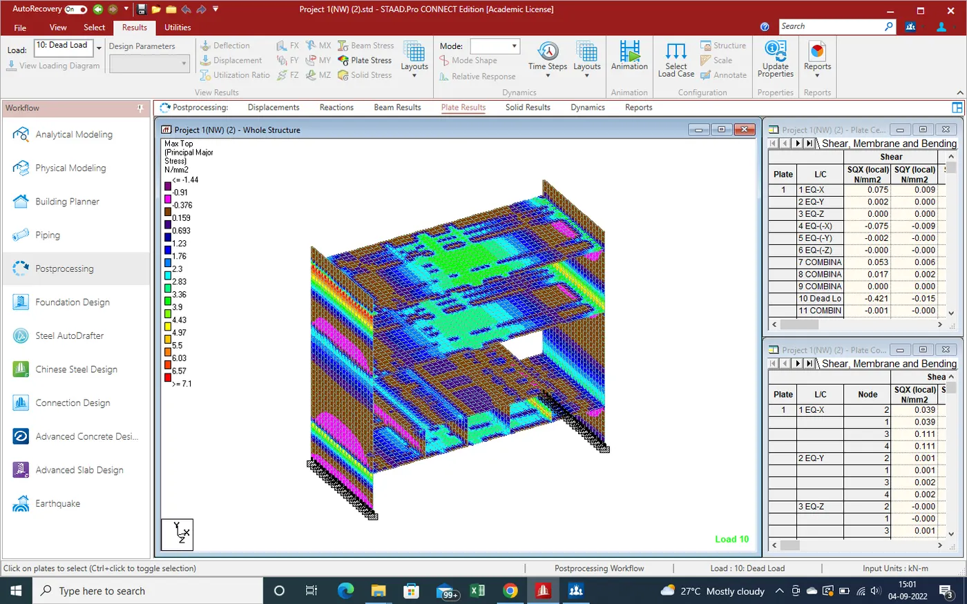
11.Deflection Due to Live load
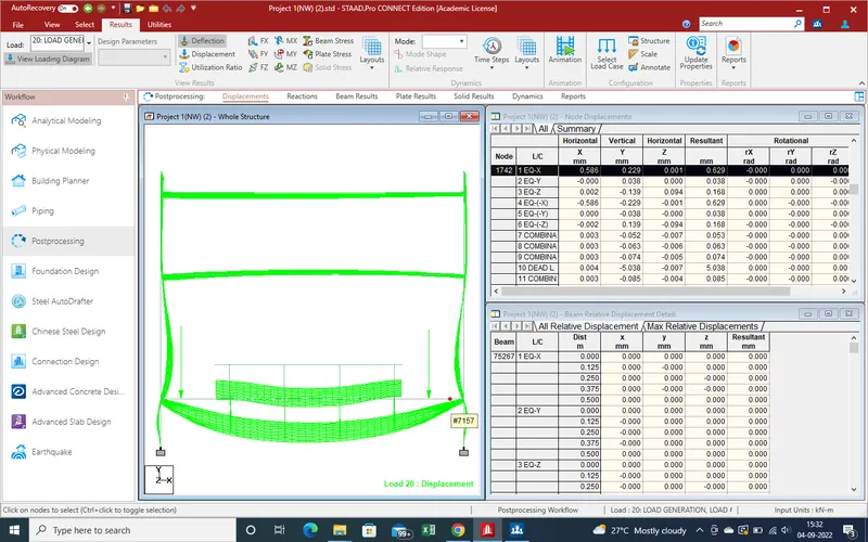
12.Plates results due to live load
6.Conslustion :-
Here we apply the Dead load ,Live load ,Earth pressure ,wind Load as well as sesmic load and get the results which pics are attached above results and master file is attached with results with reports file