Meshing of an Instrument Panel (IP) using ANSA
- INTRODUCTION
IP substrate or instrument panel substrate (also called a dashboard), is a deep-drawn injection molded part of the car. It is a long panel on which various instruments like speedometer, tachometer, odometer, turn signal indicator, active lights indicator, etc. are fitted. Nowadays, with the advent of sensors and transducers, LEDs and digital displays, running gear, the temperature of the engine, working of battery, etc. are also displayed. The IP also has the knob for changing the temperature of an AC, the music player controller system, the air vents, etc. on it. All these things show the importance that IP has in the car. Thus, it has to be made not only tough enough to act against any collision but also has to be aesthetically impressive and user-friendly.
IP is manufactured by an injection molding process with an ABS (Acrylonitrile-Butadiene-Styrene) or PPE (Polyphenylene Ether) material.[1] The ABS material does not only provide the toughness and impact strength due to the presence of butadiene, but it also provides chemical resistance, heat stability due to the presence of acrylonitrile, and rigidity and processability due to the presence of styrene.[2] Due to the presence of styrene, producing complex features becomes possible. As can be seen in fig. 1, the IP substrate geometry imported into the pre-processor software ANSA has lots of complex features present in it. In this work, this geometry is taken as a part of to mesh for further FEA analysis.
Aim
To discretize the IP substrate geometry into fine elements.
Objective
- To obtain the mid-surface of the geometry.
- To mesh all the even and uneven geometrical features of the geometry.
- To maintain the quality of the elements.
- PROCEDURE
Preparation for meshing
The IP substrate was a very complex geometry composed of many ribs and attachment parts. When the model was imported it was having so many errors present in it. The red lines, as can be seen in fig.1 are the unconnected neighboring surfaces. All such unconnected neighboring surfaces were connected using the ‘Topo’ tool.
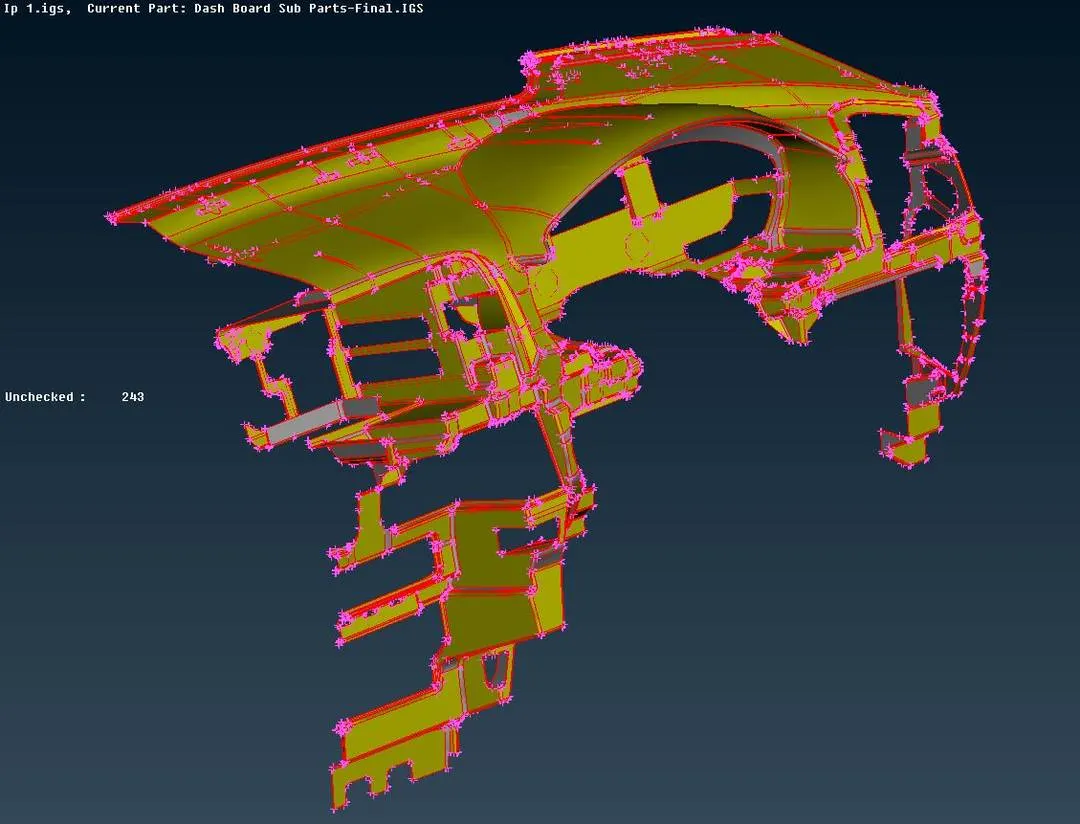
Figure 1: IP substrate geometry just after imported into ANSA.
After using that tool many errors were gone but many were developed or some of them were also present earlier. Fig. 2 shows the presence of the errors after the use of the ‘Topo’ tool. Thus all such errors were had to remove manually. Errors like needle face, the unchecked face could be removed automatically, but while doing it, in some regions, it was disturbing the feature of the model. Thus, while eliminating the errors automatically also, observation had to be kept on the region where the automatic error removal was being done.
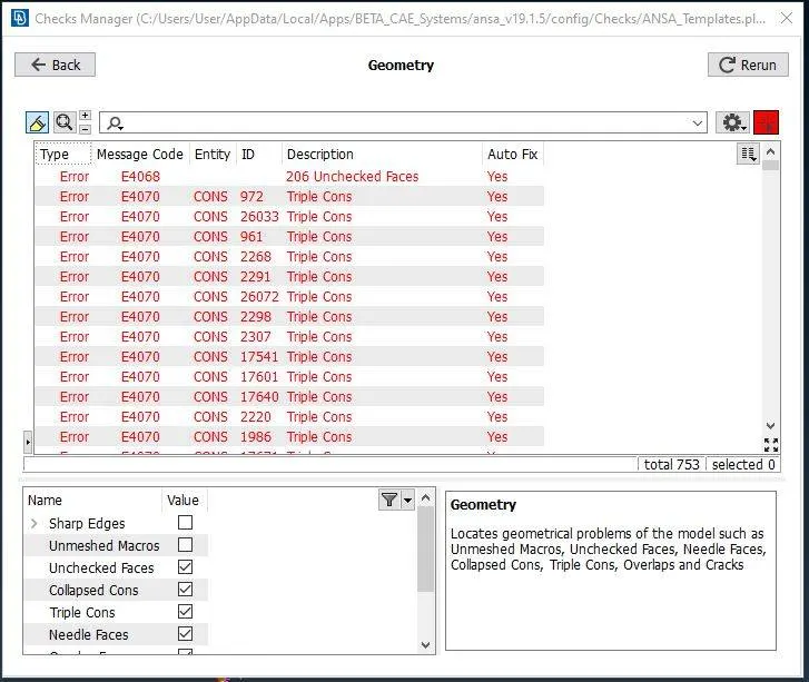
Figure 2: Number of errors present in the IP substrate model, after connecting the neighboring surfaces.
In some regions, surfaces were not present. In the absence of any surface or the presence of any kind of distortion present in the geometry, obtaining the mid-surface would become difficult. As can be seen in fig. 3(a), the surface was absent or might have gone deleted while removing the errors. Thus such surfaces were created manually, as shown in fig. 3(b), by using the curve’s tools.
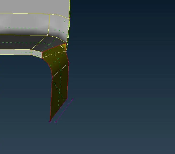
Figure 3(a): Absence of the surface.
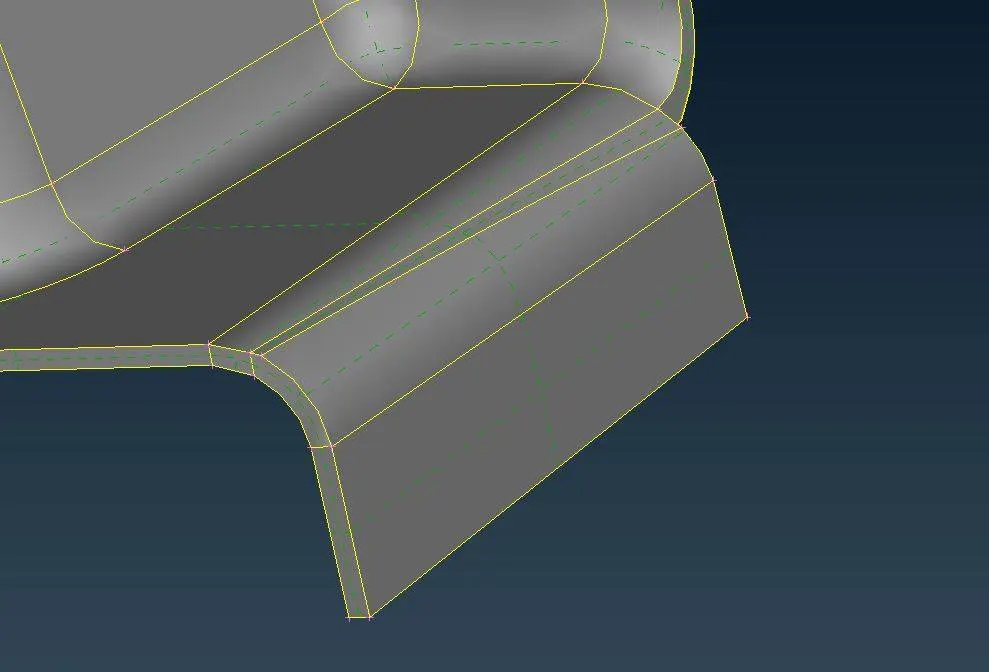
Figure 3(b): Surface that was manually created.
To obtain the mid-surface, the batch mesh was not found to be of much use. It was because the presence of varying thicknesses in some regions was making it difficult to obtain the mid-surface automatically. Therefore, mid-surface was obtained manually by offsetting the surface.
When the part was imported into ANSA, all of its parts were kept in a single PID (or property ID). When the shell mesh has to be done on any part, it has to be assigned the thickness value, so that it would act as the part as provided. In this model, many parts were having different thickness values, therefore, all such parts had to be put in the different PIDs, assigning their respective thickness. Fig. 4 shows the mid-surface of the IP substrate geometry with all the PIDs assigned. The different colors in the figure show that they are having different PIDs.
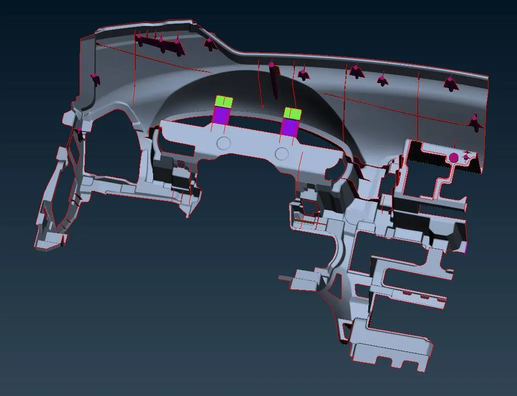
Figure 4: Mid-surface with all PIDs assigned.
But many areas were also there in the model which were having varying thicknesses as shown in fig.5. In the figure, a rib is having continuously varying thickness along its entire length. It is having a 1.953 value at the top, 2.044 at the corner, and 1.563 at the other point. Therefore in such cases, the average thickness was assigned to such geometries.
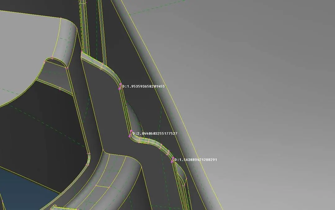
Figure 5: A rib having varying thickness along its length.
Setting Quality Criteria
The element quality criteria provided for the IP substrate model is as shown in the below table:
Table 1: Quality criteria for elements.
| Target/Average length | 4 mm |
| Minimum length | 2 mm |
| Maximum length | 6 mm |
| Aspect | 3 |
| Warpage | 15 |
| Skewness | 45 |
| Jacobian | 0.7 |
| Minimum Quad Angle | 45 |
| Maximum Quad Angle | 135 |
| Minimum Tria Angle | 30 |
| Maximum Tria Angle | 120 |
| Tria Percentage | 15% |
Discretization or meshing
Meshing is that which is one of the most important factors that play a vital role in FEA. The elements, obtained after meshing, transfers the input energy, provided as input, among the body using the series of calculations and iterations. The resultant of which can be seen as the deformation or stress obtained in the body. In this model, meshing was done gradually area-by-area. The attachment regions were meshed at first. It is because, those were the region which was having a very constrained area, and the chances of obtaining failed elements, in those regions, were more. If it were taken, at last, to mesh, adjustment of the elements would have become difficult. Thus after meshing the attachment regions, flat areas have meshed. And lastly, the ribs have meshed. Fig. 6 shows the completely meshed IP substrate model.
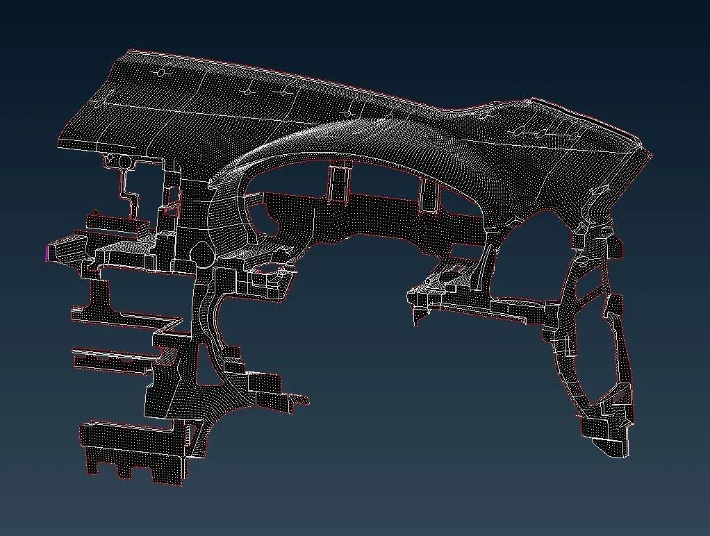
Figure 6. Mesh flow pattern.
Though after gradually meshing the model, there were 386 off elements, which was almost 0.9% of all elements. Therefore, after completing the meshing of the whole model, off elements were tried to reduce but in some regions, where the area was the constraint, off elements couldn’t be eliminated. Thus the number of off-elements was reduced to 221, which is almost 0.5% of all elements. Also, the model has 1912 trias, which is 4.38% of all elements.
- LEARNING OUTCOME
- Obtaining mid-surface of the complex geometry automatically may not give proper surface, thus manual method should be preferred, if required.
- The absence of any surface or duplicate surface should not be there. If a surface is absent, then it has to be created manually.
- If some area has a varying thickness along its length, it has to be assigned average thickness.
- A sheet that has two or more thicknesses along its length, has to be segregated and assigned the respective thicknesses.
- Complex areas have to be meshed at first.
- CONCLUSION
Meshing is the primary work of FEA (finite element analysis), that has to be done before proceeding to any further steps in FEA. It can be performed using 2d or 3d elements. But because 3d elements have more number of nodes, it takes more time to compute. Therefore, in parts in which sheet is used shell elements or 2d elements are used, on the mid-surface of the sheet. While meshing also, the quality of the elements and its flow has to be maintained, so that the output result may come close to the accurate value.
References
[1] https://www.automotiveplastics.com/automotive-plastics-today/interior/
[2] https://omnexus.specialchem.com/selection-guide/acrylonitrile-butadiene-styrene-abs-plastic