REVIT _3D Rendering of a house plan _ Project 1
1) AIM : To model a ceiling from architecture tab above the walls at first floor level
TOOLS USED :
- Architecture
- Ceiling
- Sketch ceiling
PROCEDURE :
- Open the file in Revit
- Open the first floor plan
- Go to architecture tab and select ceiling command and choose sketch ceiling
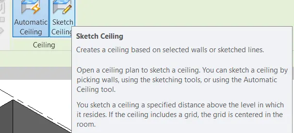
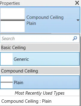
- Select the type of ceiling from property browser
- Draw the ceiling and check it in 3D view
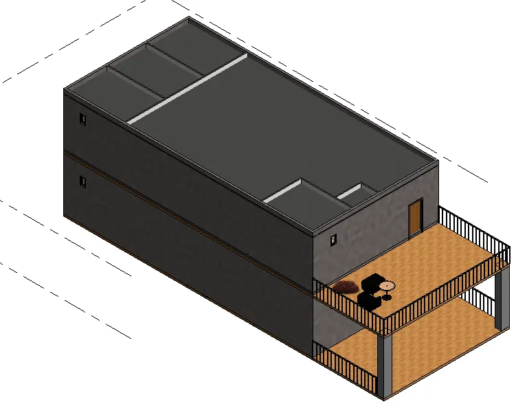
RESULT : Ceiling is drawn by following above procedure
2) AIM : To model a roof by foot print method at a slope of 10°
TOOLS USED :
- Architecture
- Roof by footprints
- Manage
- Project units
PROCEDURE :
- Open the project file in Revit
- Go to manage tab and click on project units and select slope and degree
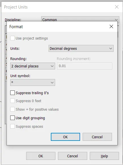
- Go to architecture tab and select roof by footprints
- Select the lines and draw the roof
- Choose the roof material form property browser
- Set slope to 10°
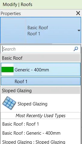
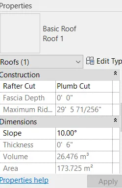
RESULT : A roof is drawn using footprints of ceiling and roof slope is adjusted to 10°
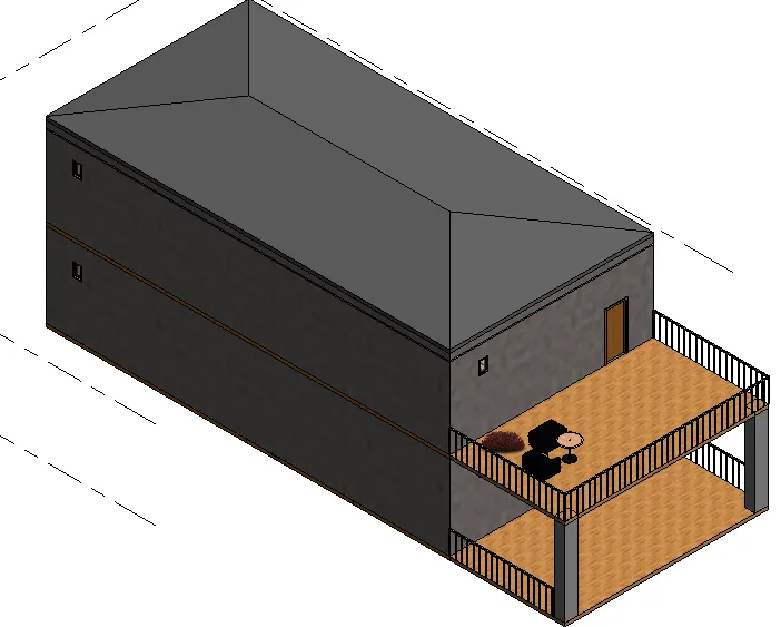
3) AIM : To create plan views for ground floor level and first floor level and to separate them as architectural and structural plans
TOOLS USED :
- View
- Plan views
PROCEDURE :
- Open the file in Revit
- Go to view tab
- Select plan views
- Rename the view
- Select the floor plan as ground floor level and the floor plan is shown
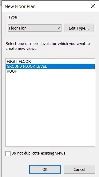
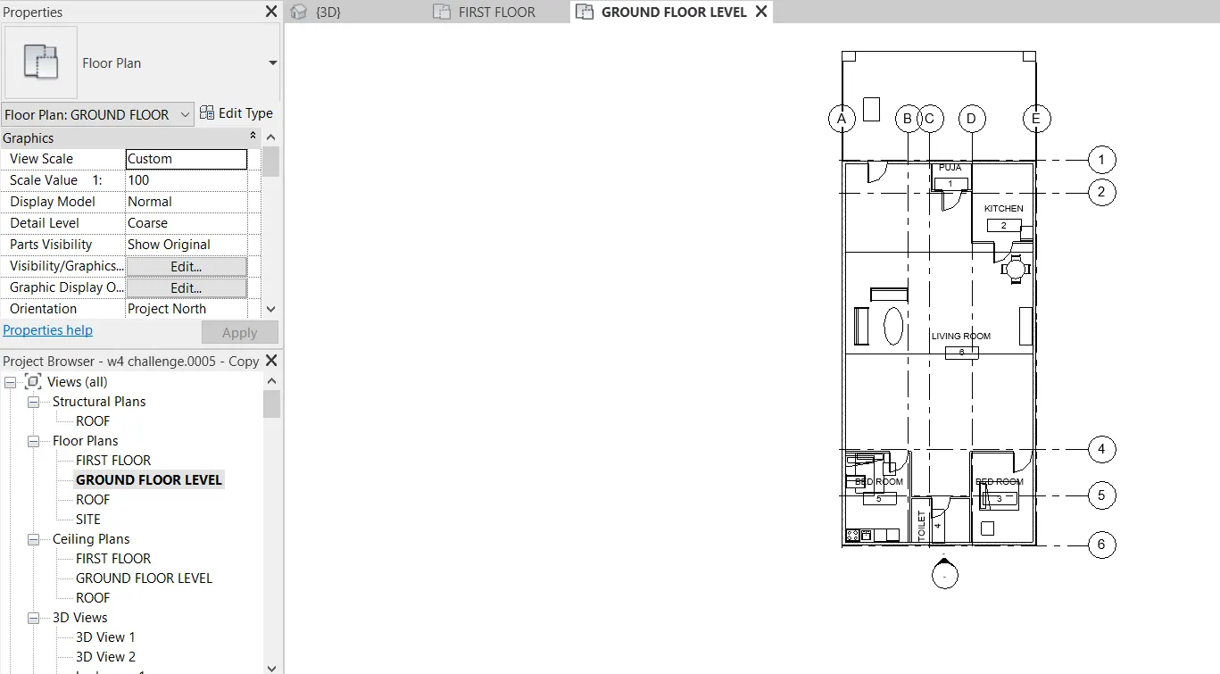
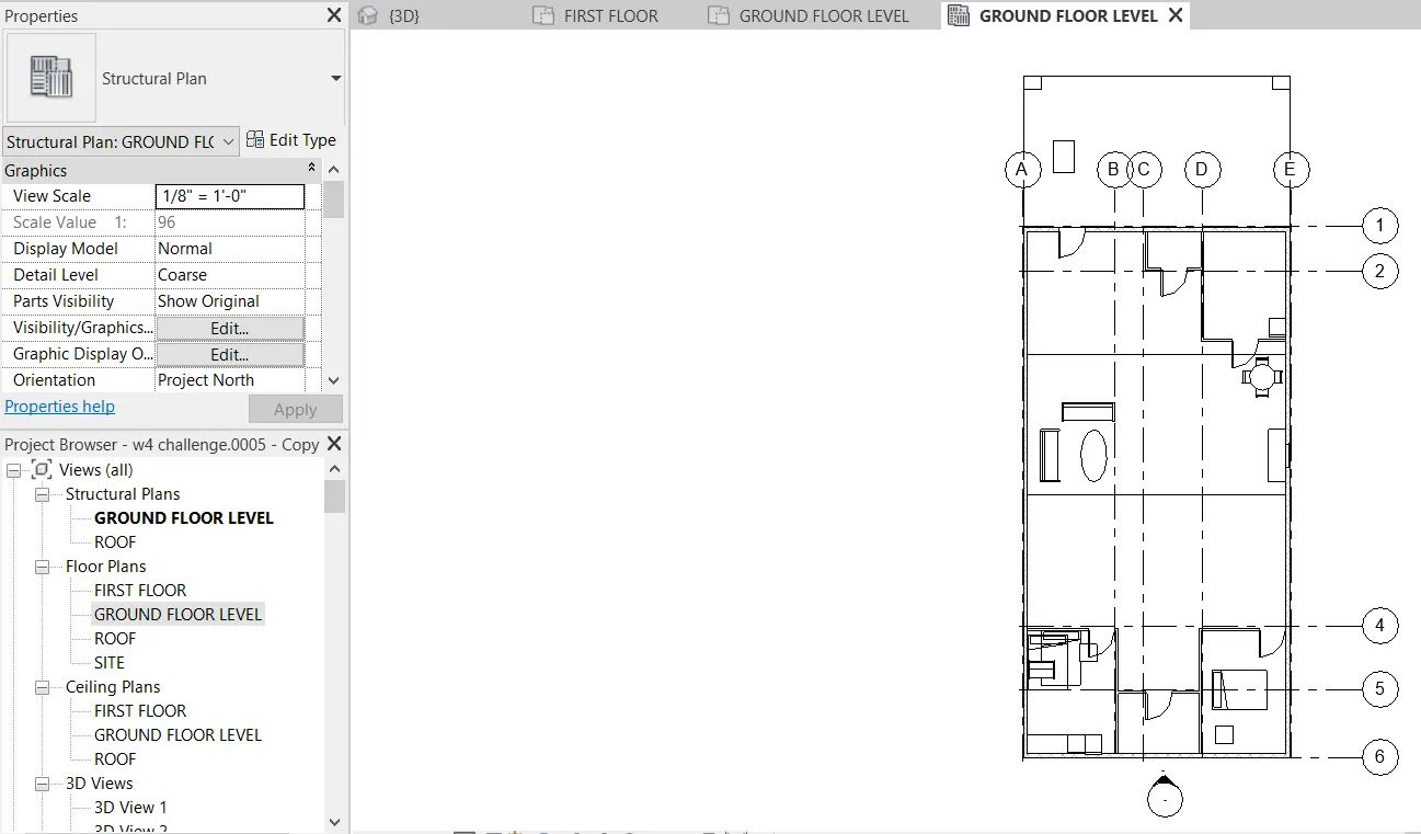
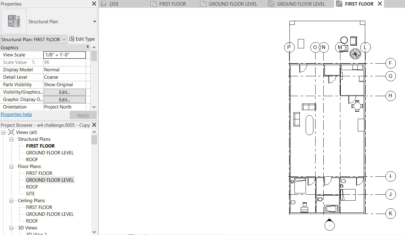
RESULT : Plan views are created for ground floor and first floor levels. And the plans are separated as architectural and structural as shown below
These are the architectural plan view which contains all detail elements for the respective rooms
These are the structural plan view as it contains information of walls and Columns
4) AIM : To add dimensions to all walls and floors using transverse and longitudinal grids
TOOLS USED :
- Architecture
- Grids
- Annotate
- Linear
- Aligned
PR0CEDURE :
- Open the project file in Revit
- Go to architecture tab
- Click on grids
- Draw grids with equal interval horizontally and vertically
- Rename the horizontal and vertical grids
- Go to annotate tab and select aligned or linear command
- Do the detailing with reference to grids
- Follow the same procedure to architectural and structural components
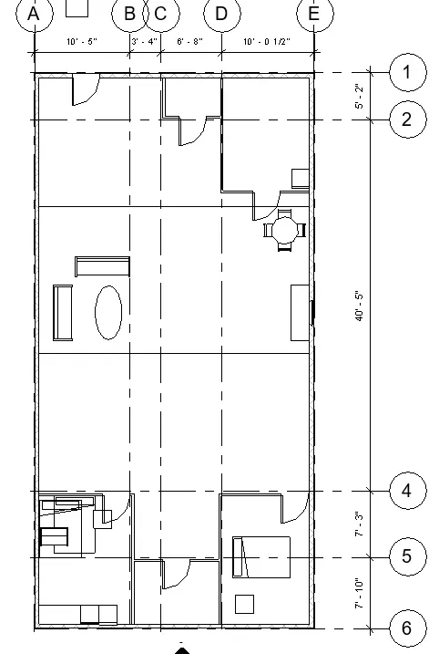
RESULT : Dimensions are added to walls and floors and other components with reference to grids
5) AIM : To create a sheet template from view tab and to adjust parameters on the sheet to add appropriate views
TOOLS USED :
- View
- Sheet
- Load items
PROCEDURE :
- Open the project file in Revit
- Go to view tab
- Select the sheet option
- Load the items and select the title block and templates
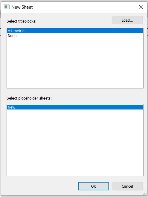
- Double click on the parameters in title ( name..)
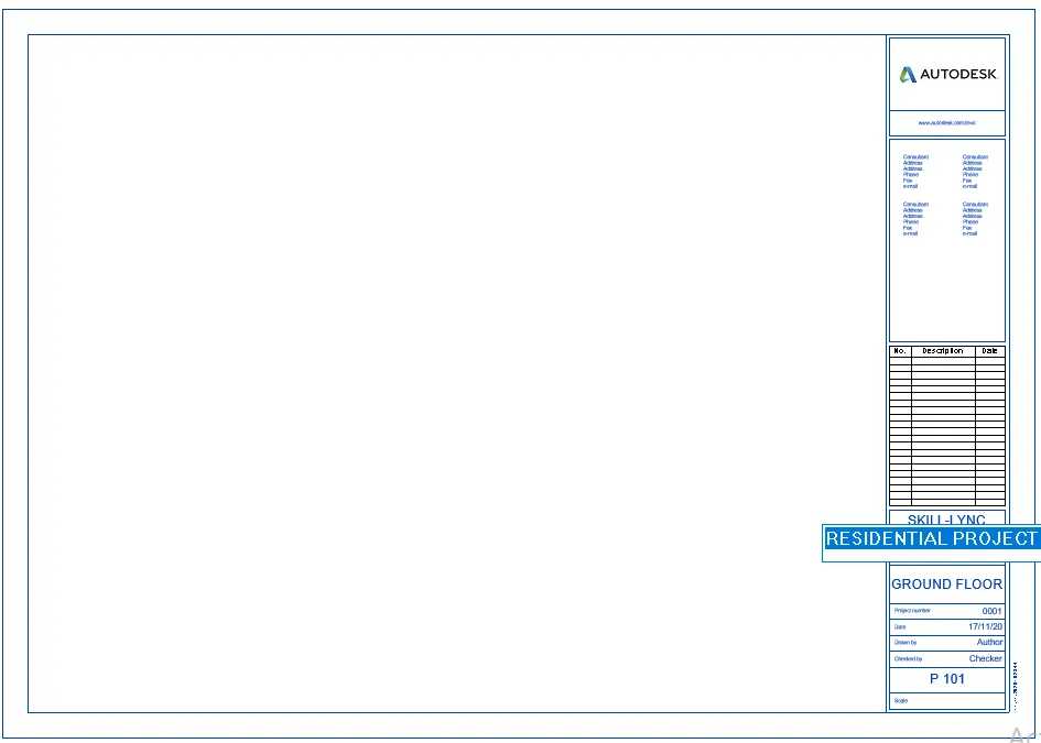
- Fill them with suitable titles
RESULT : A sheet is created and parameters are adjusted to add appropriate views
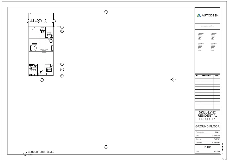
By dragging the ground floor plan from property browser, sheet is created for ground floor plan
6) AIM : To create elevation view using elevation tab in all four directions
TOOLS USED :
- View
- Elevation
PROCEDURE :
- Open the project file in revit
- Go to view tab and choose elevation option
- Select the point where elevation is required in a residential building
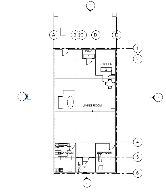
- Double click on the elevation icon and see the elevation view
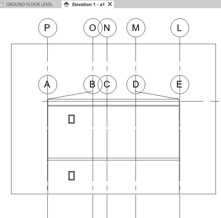
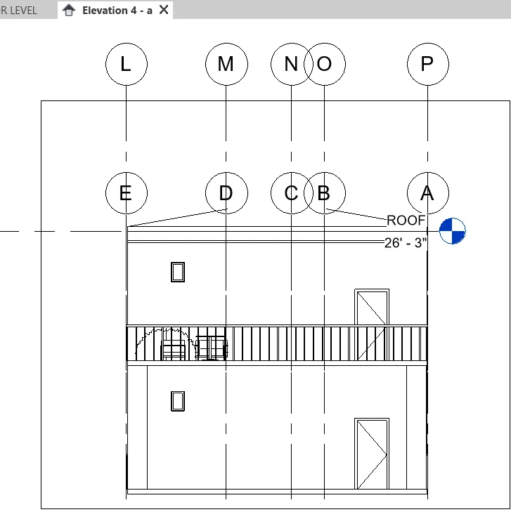
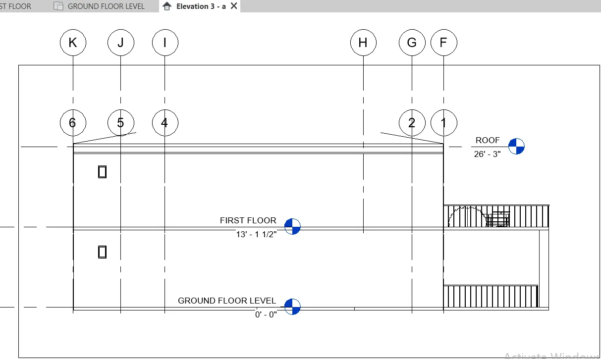
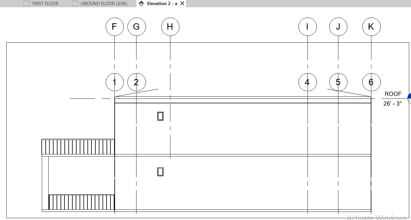
RESULT : Elevation views appeared in all directions using elevation option
7) AIM : To create section cut longitudinally or transverse direction
TOOLS USED :
- View
- Section
PROCEDURE :
- Open the file in revit
- Go to view tab and select section command
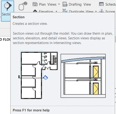
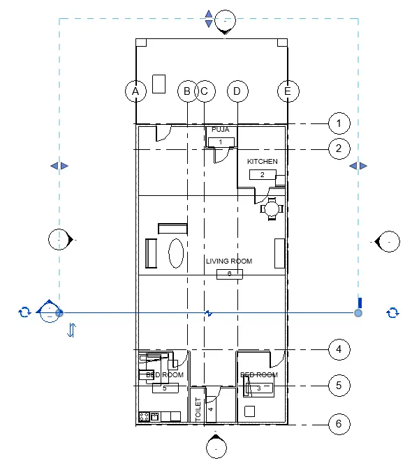
- Draw the section in the floor plan either longitudinally or transverse direction
- Double click on the section to check the section view
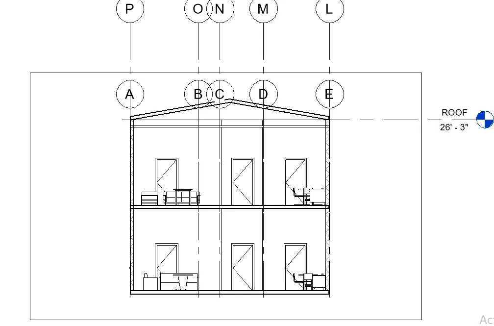
RESULT : Corresponding section views are created
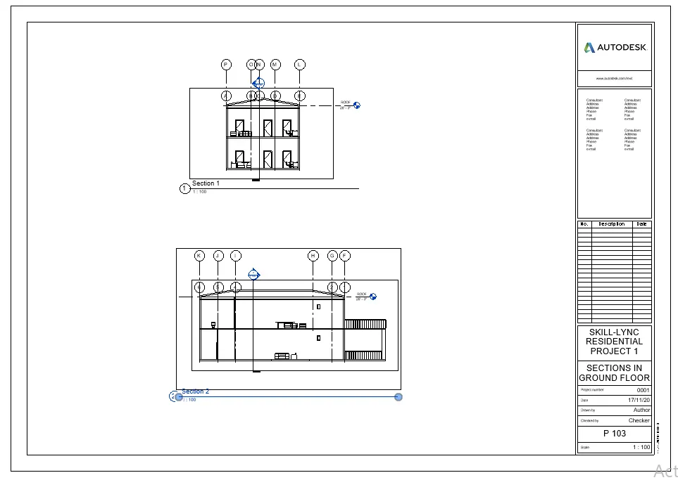
8) AIM : To classify the plan views, section views and elevation views for design or documentation category
TOOLS USED :
- View
- Sheet
- Load items
PROCEDURE :
- Open the project file in revit
- Go to view tab and select sheet option
- Choose the load items and select the required template
- From the property browser, drag the plans to the sheet and select the appropriate scale in the property and set the appropriate scale
- Double click on the text in sheet and do the detailing as required
RESULT :
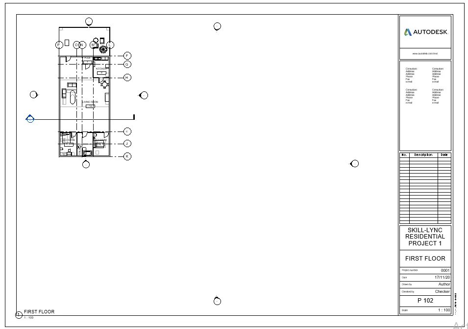
- View is ready for documentation part
- These are some views which i have made
9) AIM : To create multiple sheets as follows
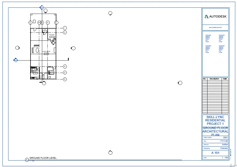
- A 101 - Ground Floor Architecture Plan
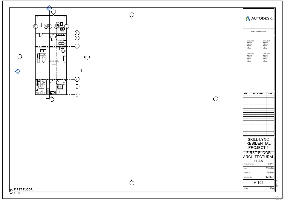
- A 102 - First Floor Architecture Plan
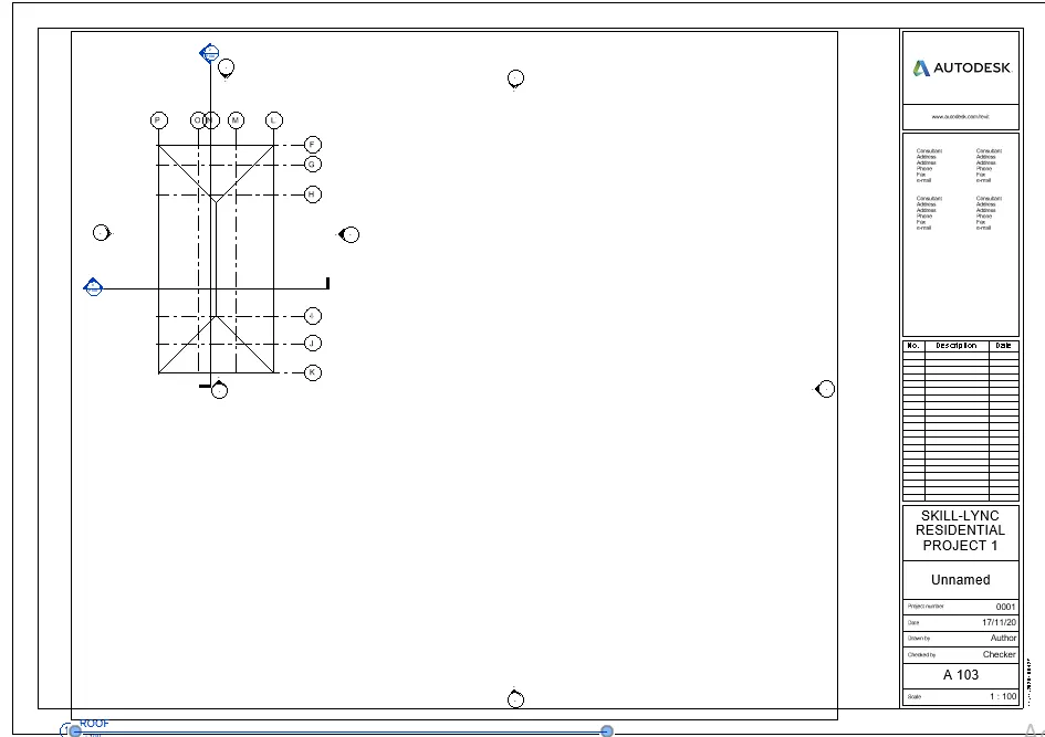
- A 103 - Roof Plan
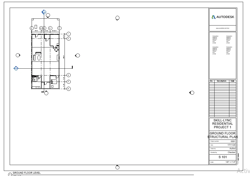
- S 101 - Ground Floor Structural Plan
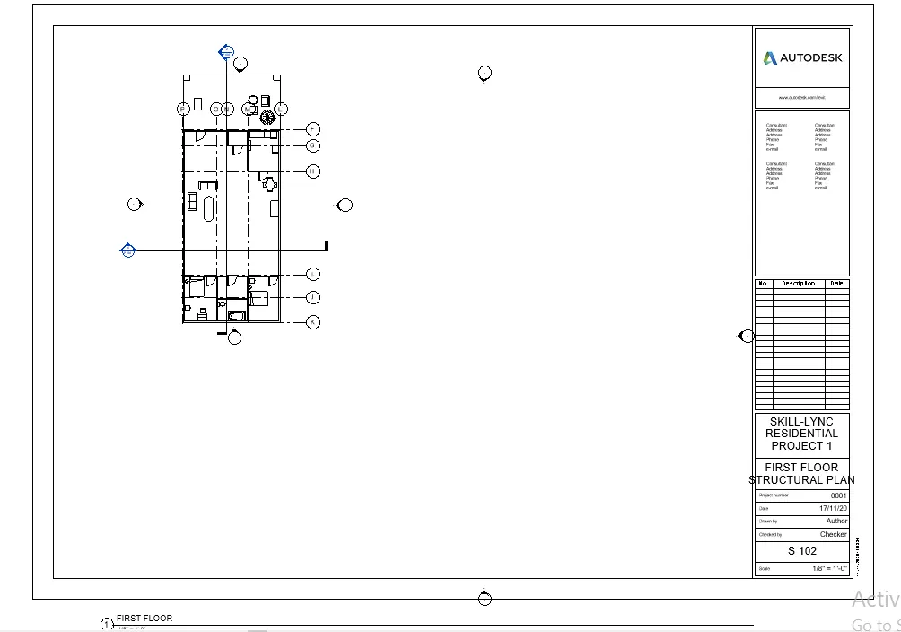
- S 102 - First Floor Structural Plan
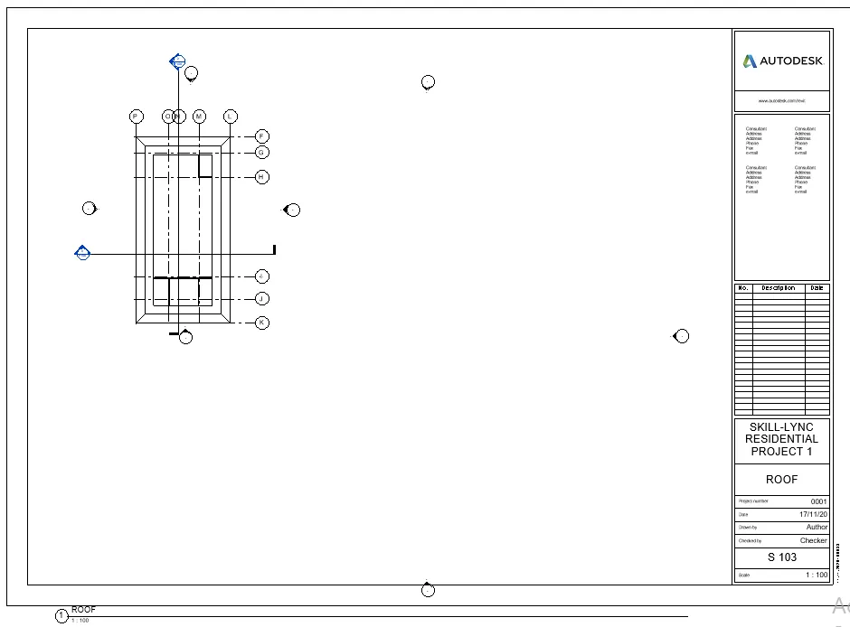
- S 103 - Roof Framing Plan
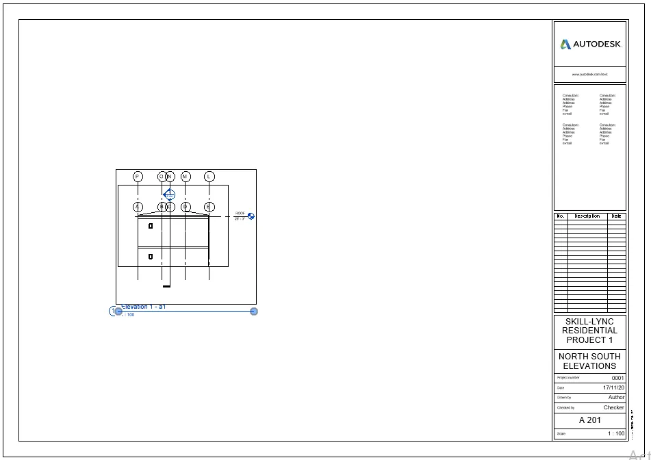
- A 201 - North south elevations
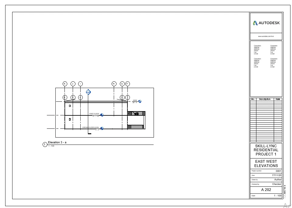
- A 202 - East West Elevations
TOOLS USED :
- View
- Sheet
PROCEDURE :
- Open the file in revit
- Go to the view tab and choose sheet option
- Select the plans from the property browser and drag it to the sheet
- Select the appropriate scale and name the drawing number and title as required
RESULT : Multiple sheets are created as required
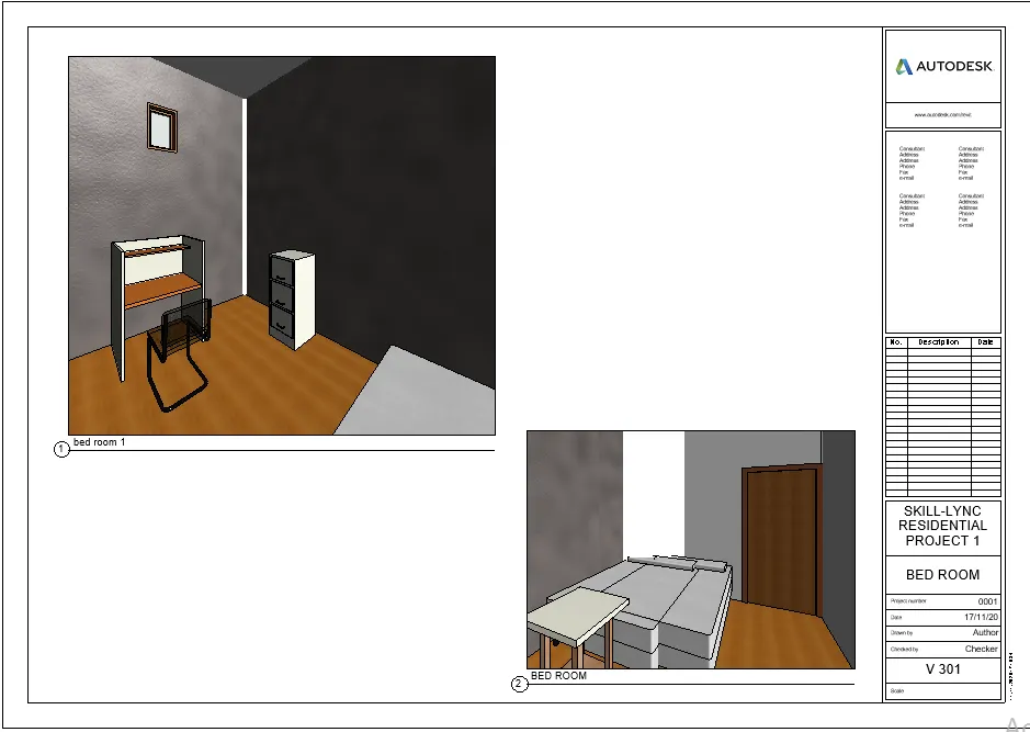
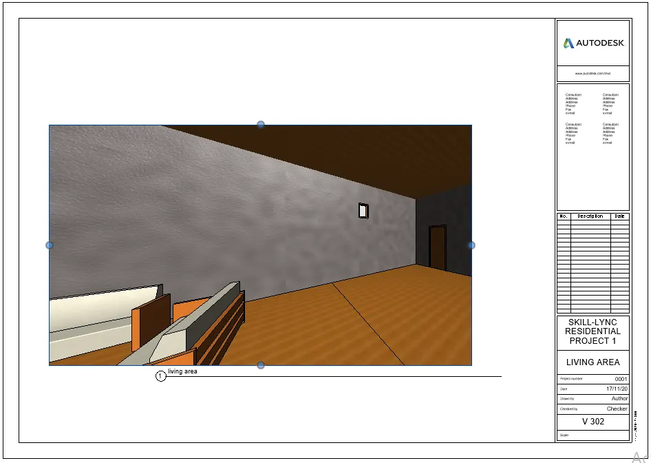
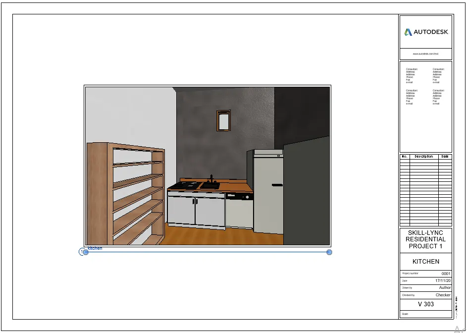
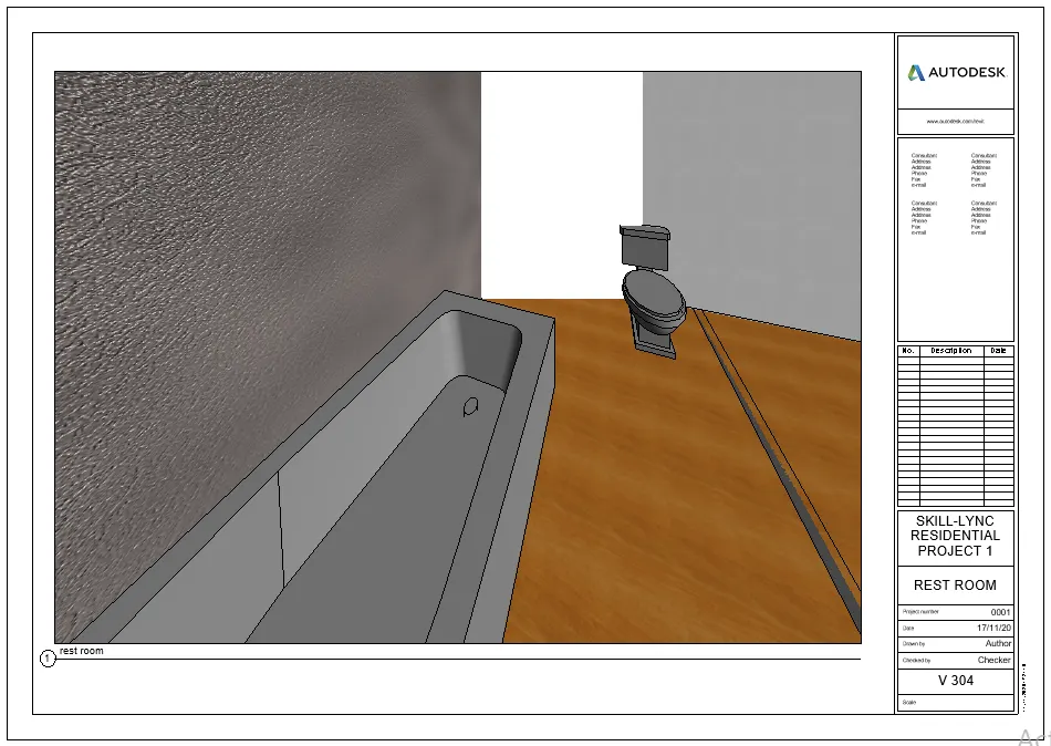
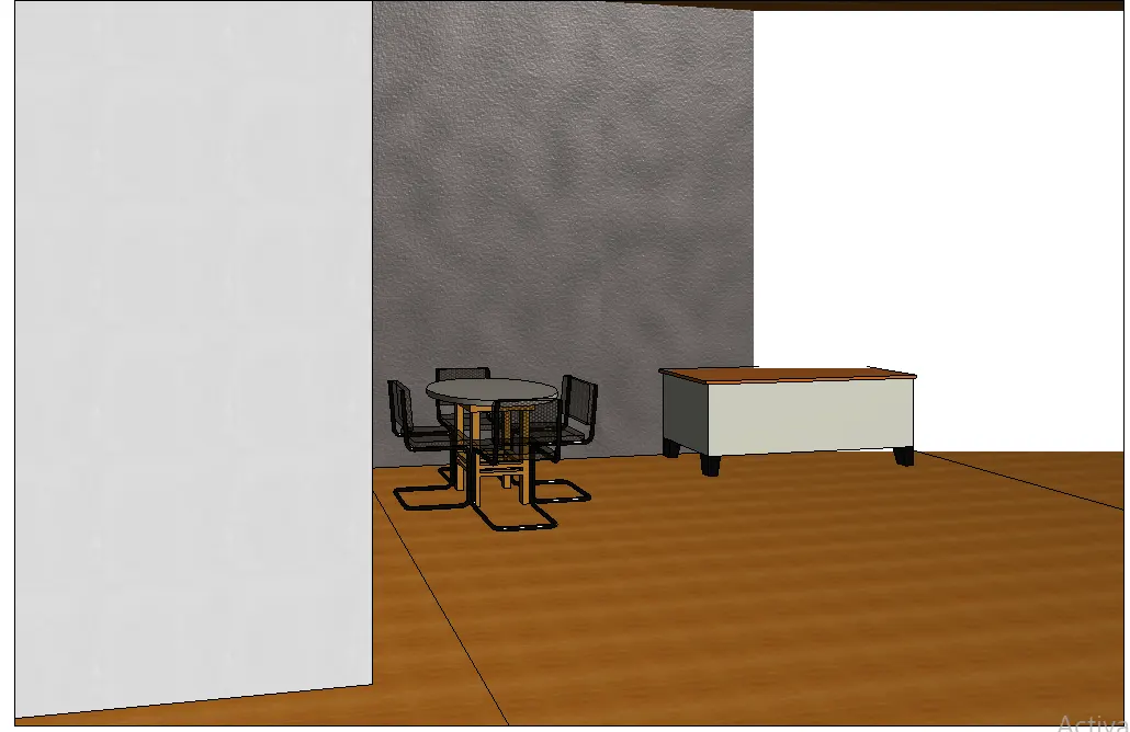
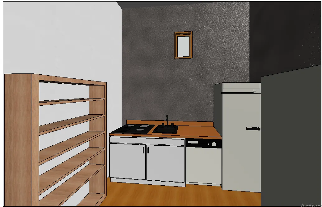
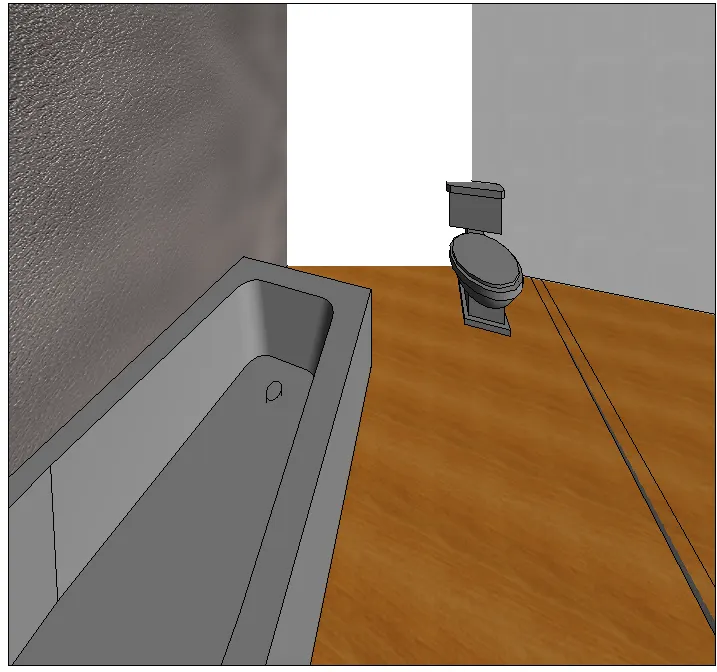
10) AIM : To create a 3D view in each room and to add them in sheets respectively
TOOLS USED :
- View
- Sheet
- Camera
PROCEDURE :
- Open the file in revit
- Go to view tab and select camera in 3D view option
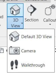
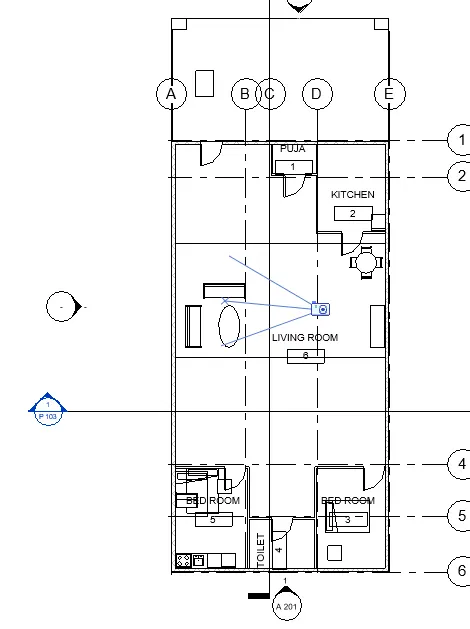
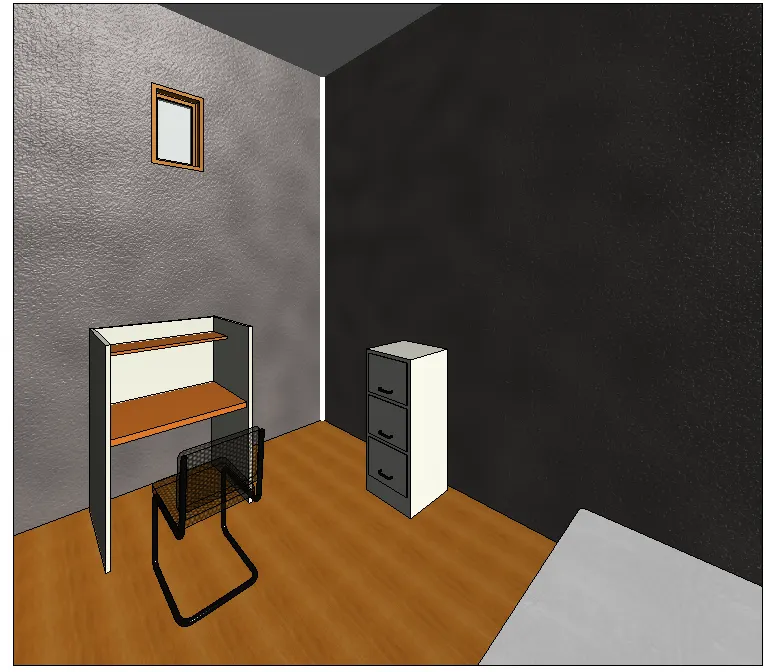
- Place the camera in each room and save them as respective view
- Again go to view tab and Select sheet and load the title block
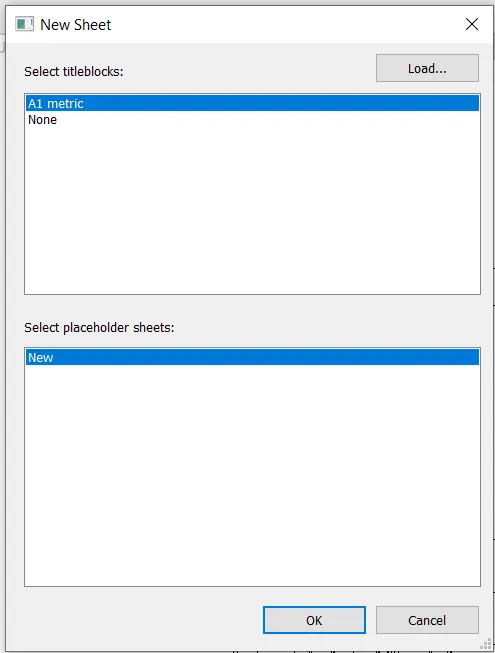
- Drag the 3D views of different rooms in different sheets with same procedure
RESULT : The following sheets are created