Project 1
5th Ans)
AIM : To create a sheet template from the view tab and adjust the parameters on the sheet to add appropriate views
TOOLS USED :
Properties
Sheet
PROCEDURE :
a) Select architeture template.
b) Now click on view in the top.
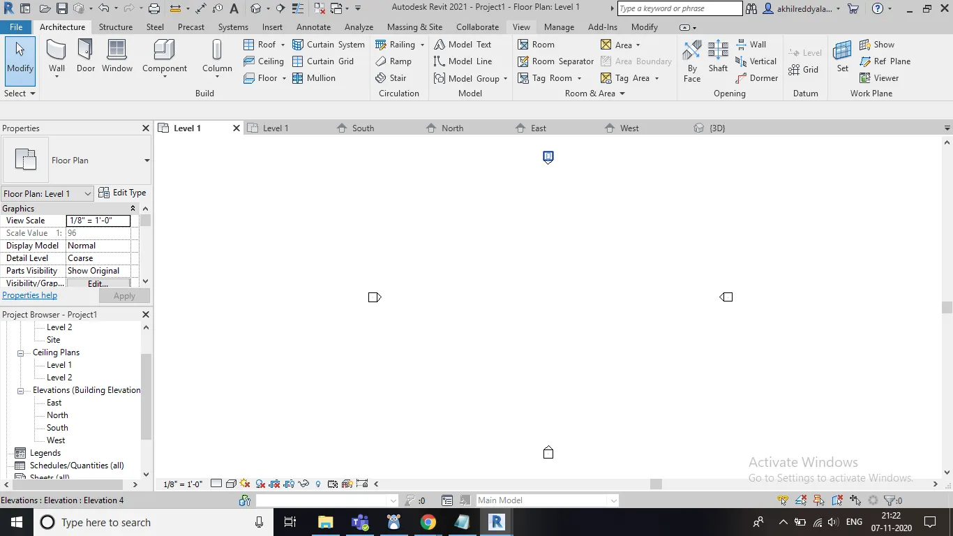
c) Select sheet option.
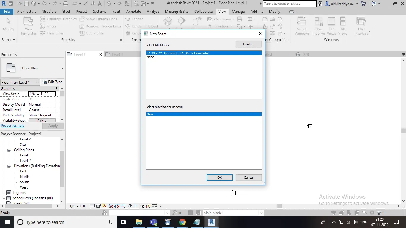
d) Now you can notice that a new sheet will obtain.
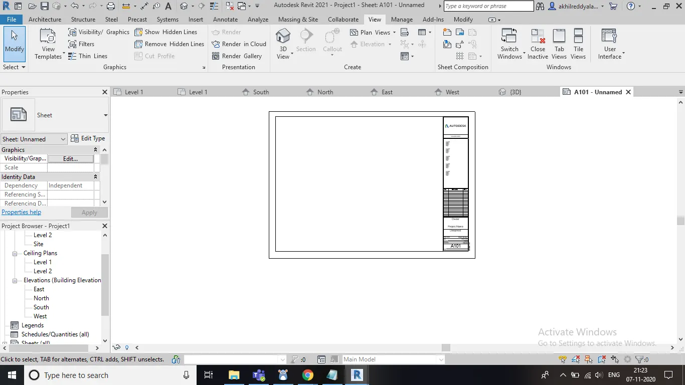
e) Now go to properties and change the details of that.
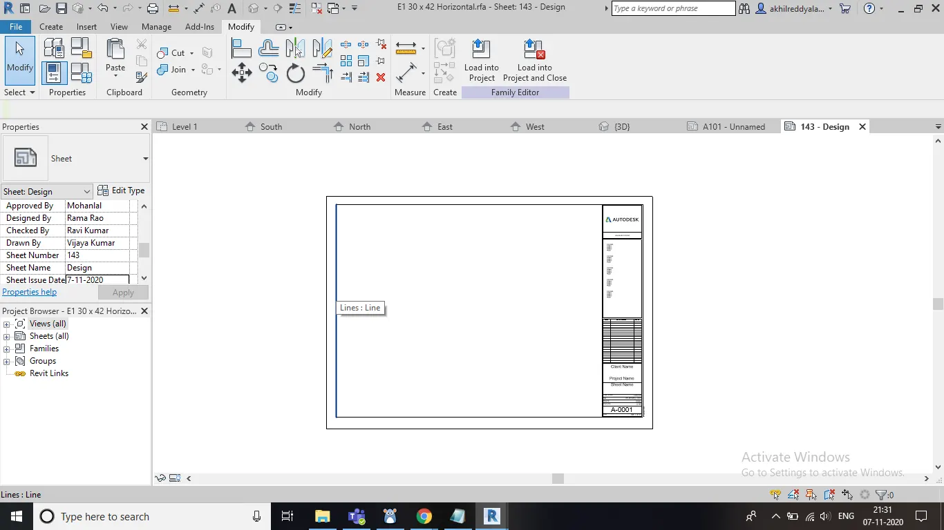
f) There will be different details present over there.
g) They are organization name ,issue date , project name , designed by, checked by etc.
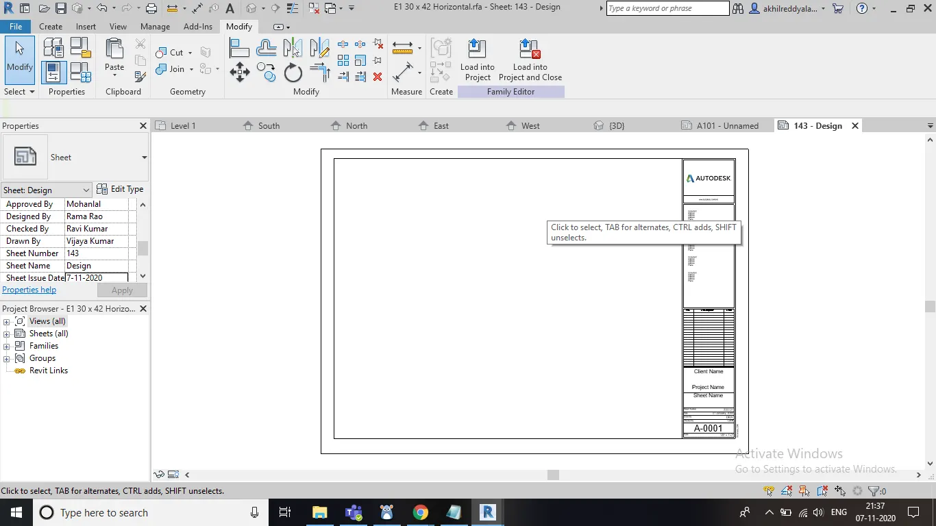
h) Fill the details according to your convienence.
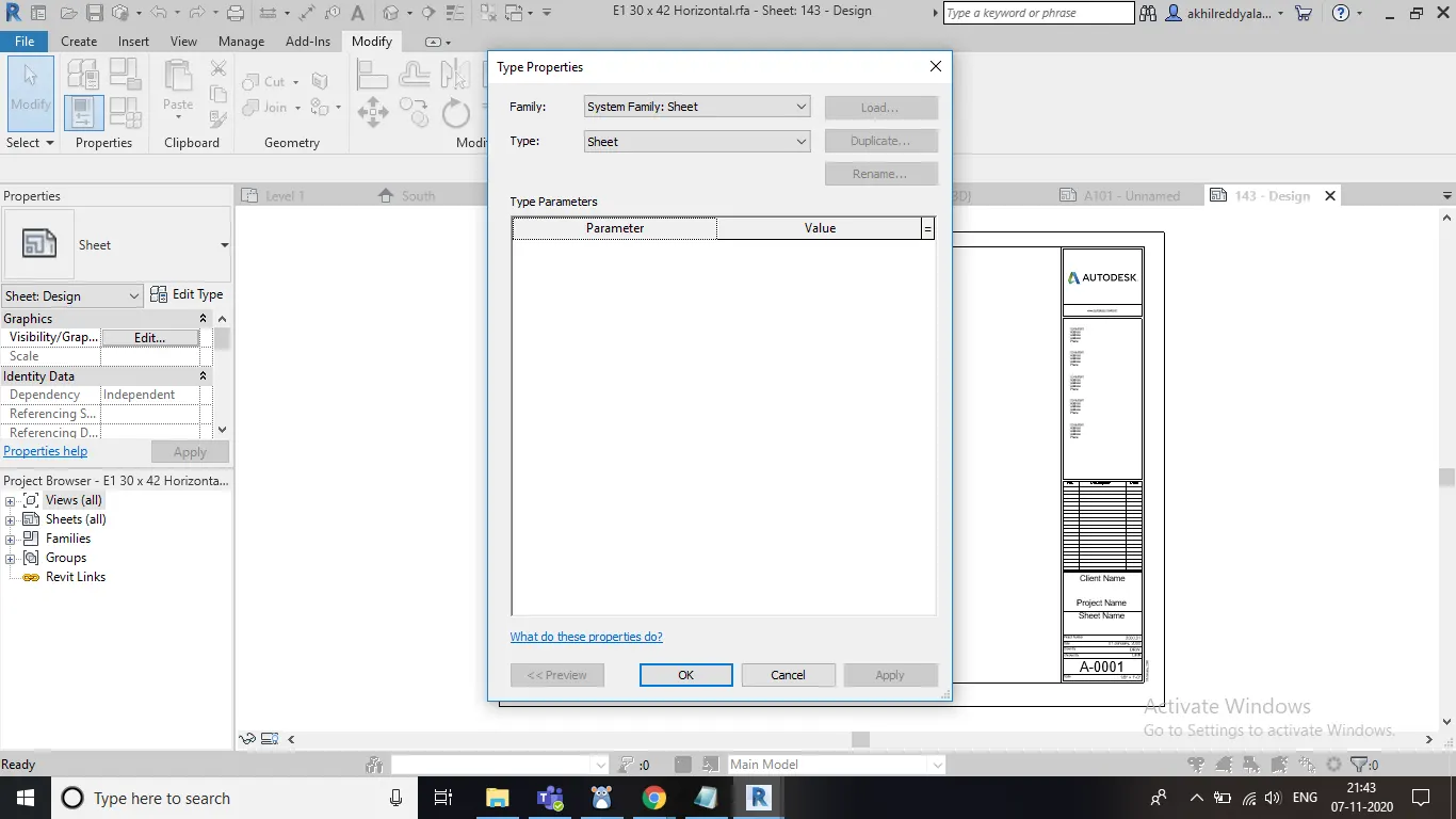
i) Take screenshot of the sheet after filling all the details.
RESULT : Sheet template was created from the view tab and the parameters were adjusted on the sheet to add appropriate views.
4th Ans)
AIM : To create transverse and longitudnal grid lines in an architectural plan which includes different rooms and components in it.
TOOLS USED :
Components
Grid
Annotate
Allign
PROCEDURE :
CASE 1 ;
a) Initially draw a 2D plan.
b) Divide it into different rooms.
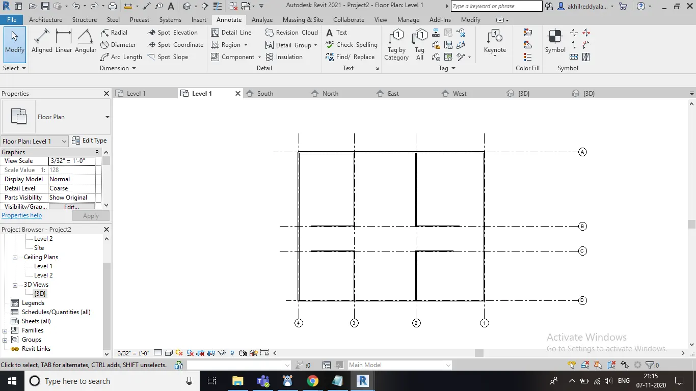
c) Go to insert and select load family.
d) Now load whatever components you want like bed , sofa , desk, table etc.
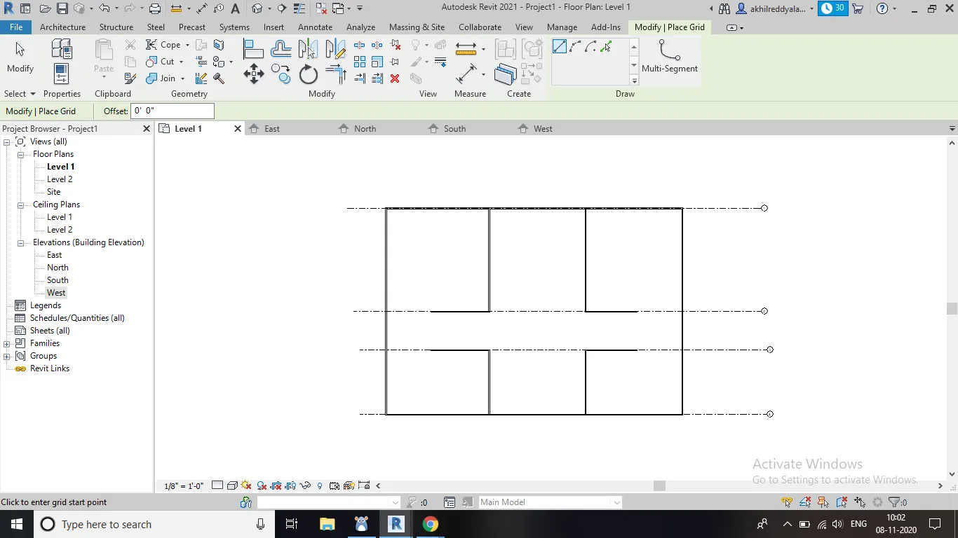
e) Then go to arhiteture template and select grid option.
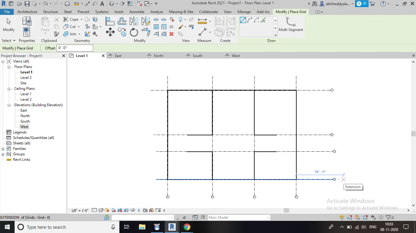
f) Now draw grid lines on all external walls , interior walls and components.
g) Use aligned option from annotate tool bar to locate dimensions between two successive grid lines.
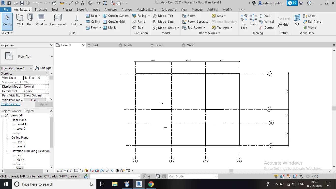
h) Measure distance between two grid lines.
i) Take all necessary screenshots.
RESULT : Grids are attatched to whatever components you want.And the distance between two successive grid lines is measured.
CASE 2 ; It was not explained in videos.
7th Ans)
AIM : To draw section views to different types of rooms present in your plan.
TOOLS USED :
Wall
Grid
view
Section
PROCEDURE :
a) Draw a simple 2D plan.
b) Place some rooms in it.
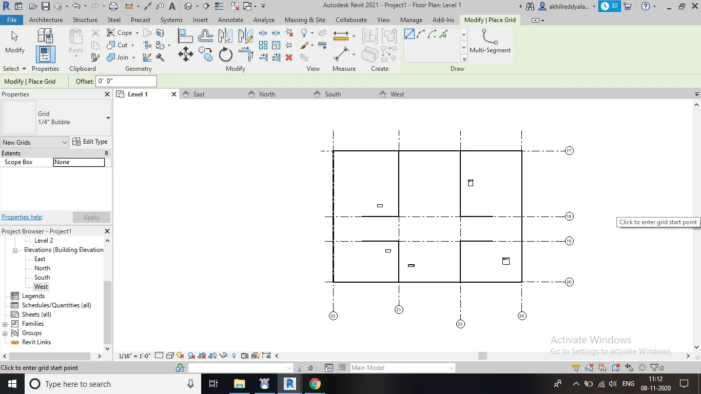
c) Now select grid option and draw grid lines on each wall.
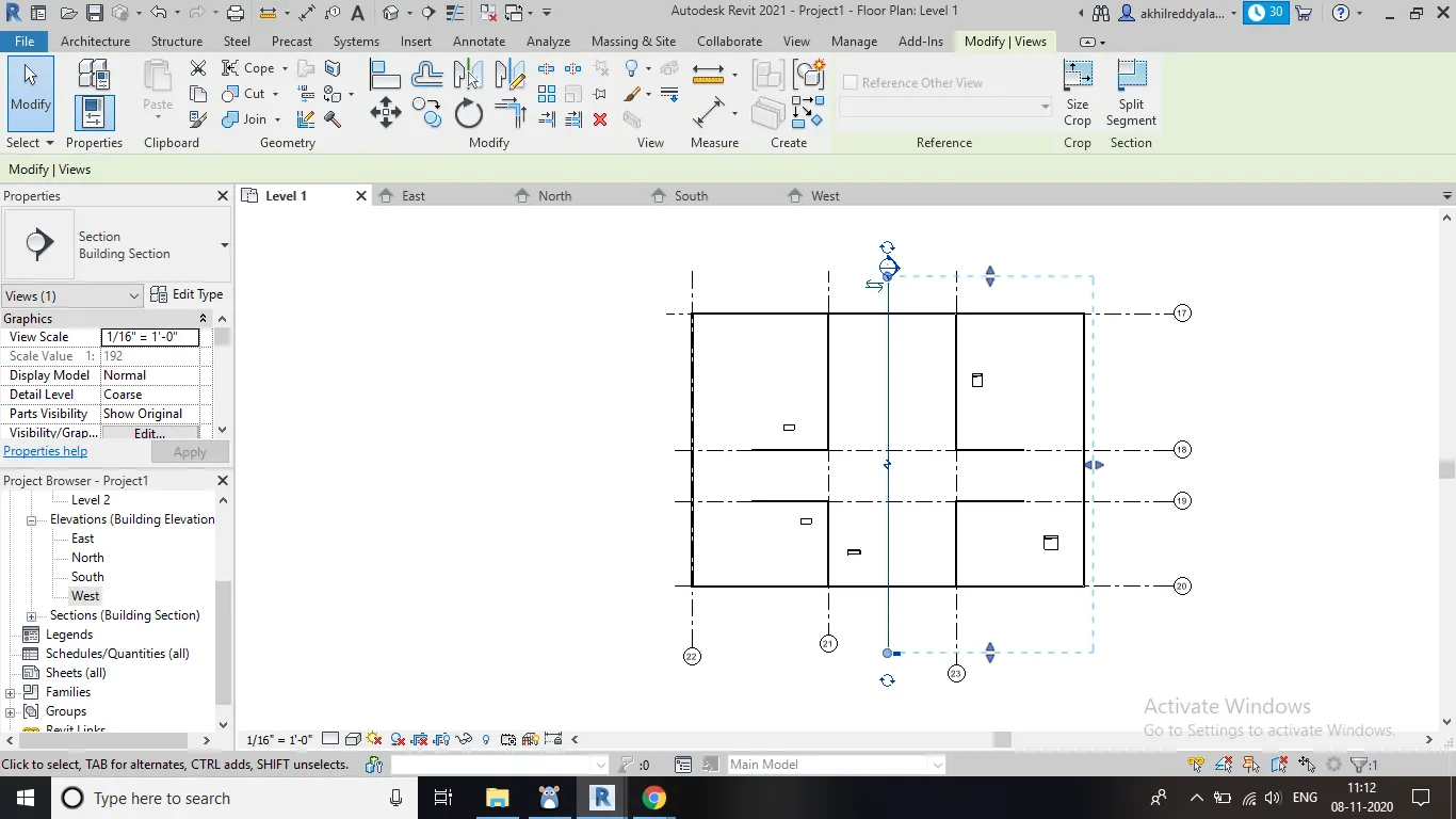
d) Draw grid lines in both horizonal and vertical lines.
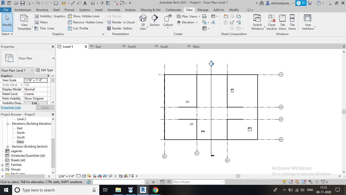
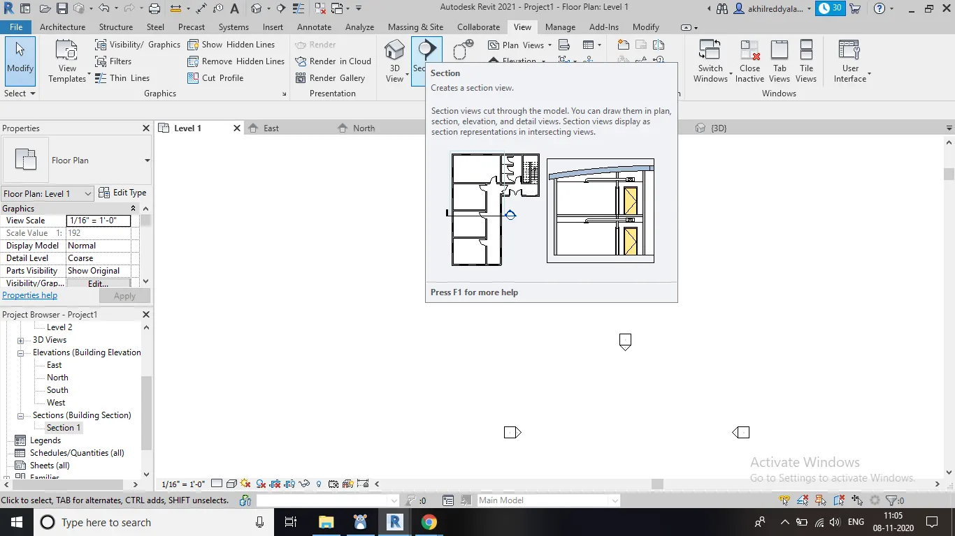
e) Now select section option in the top most tool bar.
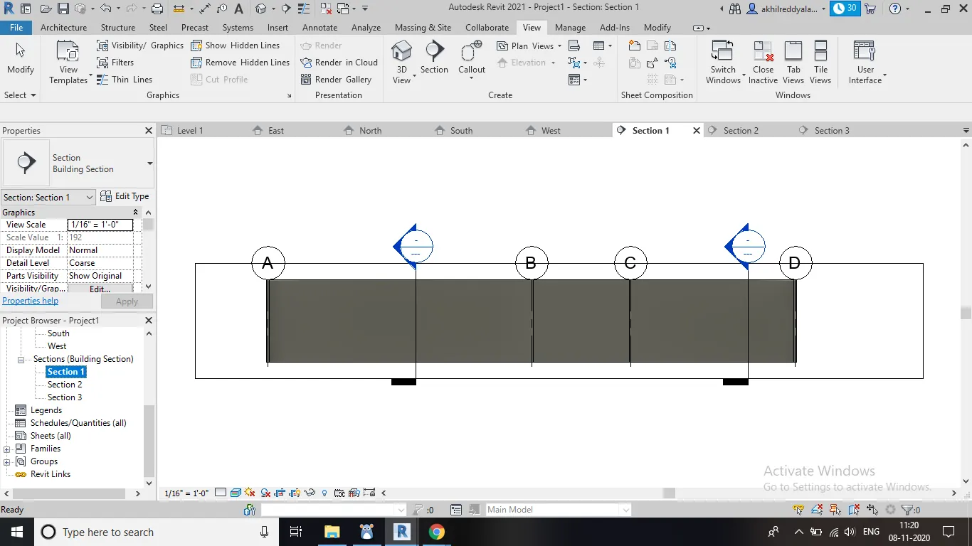
f) Select section in different rooms.
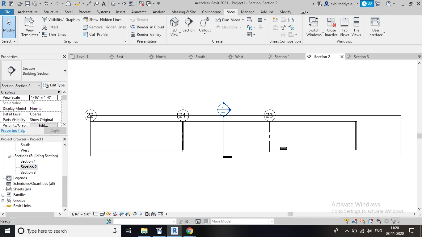
g) Now go to properties . You will find section.
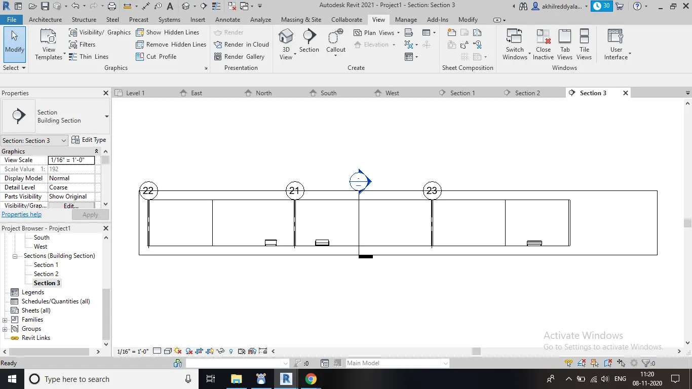
h) Click on deifferent sections and take screenshots.
RESULT : Section views are drawn to different rooms of our plan.
8th Ans)
There are different views . They are plan views , section views, elevation views.
PLAN VIEWS :
It consists of different levels like level 1 , level 2, level 3 etc. By default level 1 will be treated as ground floor. We can rename those levels as first floor , second floor. Those options will be visible in properties browser which will be present at the left side of our screen. With this property we can generate any number of floors only by selecting ground floor alone.
ELEVATION VIEW :
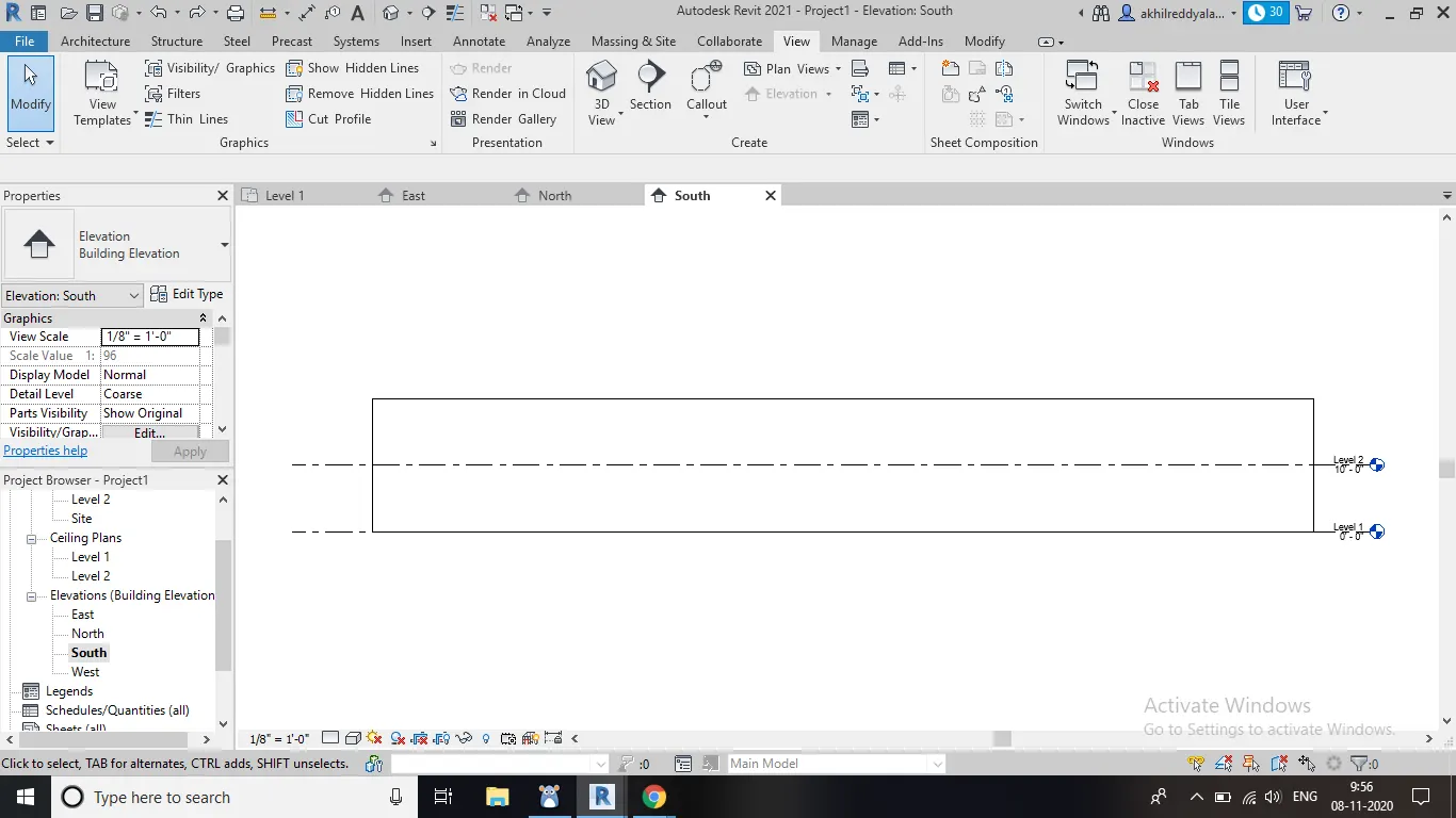
This is type of view through which different elevations an be seen. For this we need to select elevation option in the view menu on the top. It will be loaded in the property browser. There will be different options like east, west, north and south. For example if you double click on east , then the view will be appeared in east direction. Similarly select other options like west , north and south. The plan will be loaded and appeared in different elevations respectively.
SECTION VIEWS :
Section views are used to place the sections in the 2D plans. For this we need to go to view option and select 3D options.
10th Ans)
AIM : To create camera specific views of different rooms and inserting them
in different sheets.
TOOLS USED :
View
Camera
Insert
load image
PROCEDURE :
a) Initially draw a plan.
b) Draw different rooms in it.
c) Place few components in it.
d) Now click on 3D view option which is present in the top menu bar.
e) Select camera option from that.
f) Place camera in different rooms where different components are placed in different rooms.
g) See them in a 3D view.
h) Take screenshots of all those views.
i) Then go to view option and select sheet template.
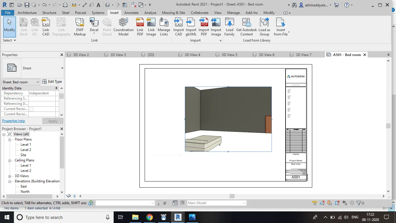
j) Rename the obtained sheet as A501 bed room and the load the sreenshot bed room view
.
k) Rename another sheet as A502 kitchen and add load screenshot of the kitchen.
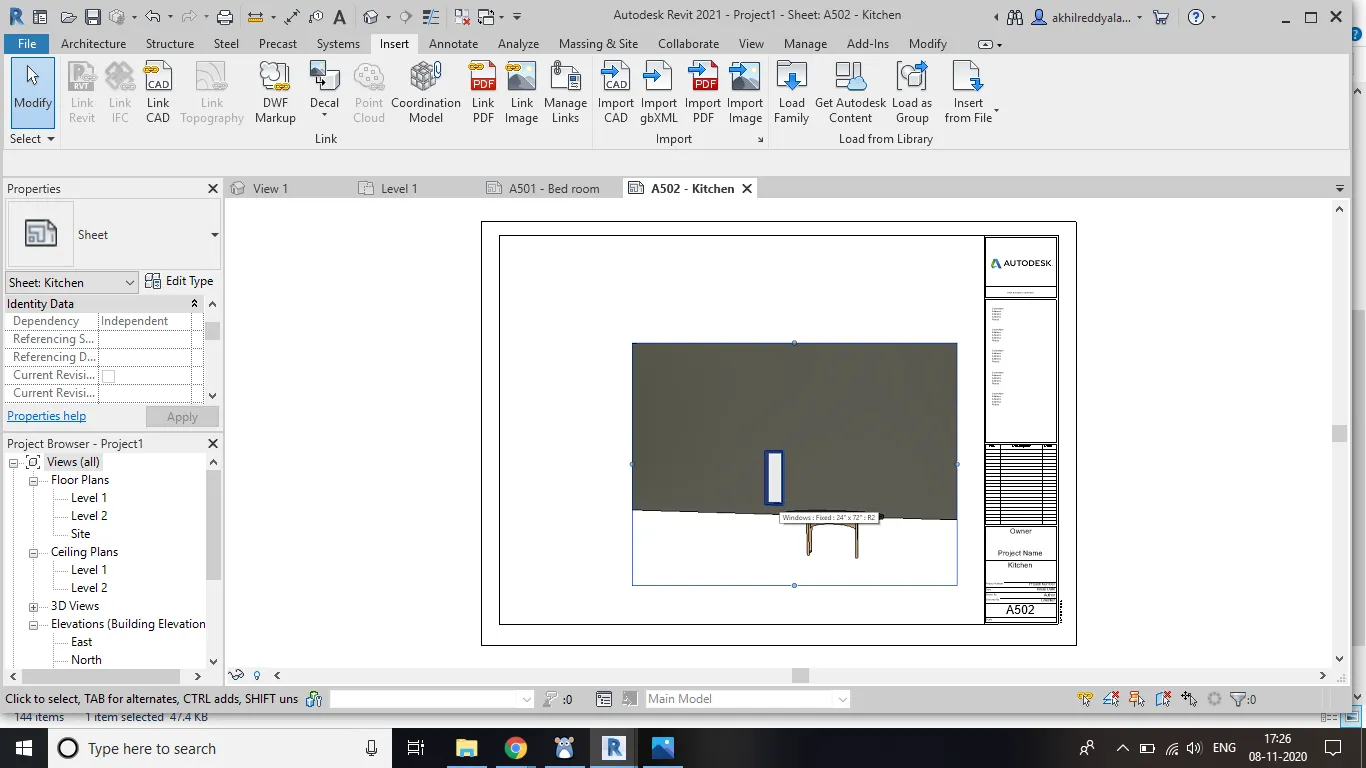
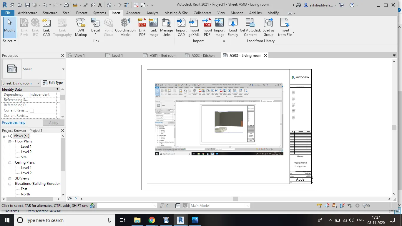
l) Rename another sheet as A503 living room and load screenshot of the living room.
m) Rename another sheet as A504 dining room and load the sreenshot of the
dining room.
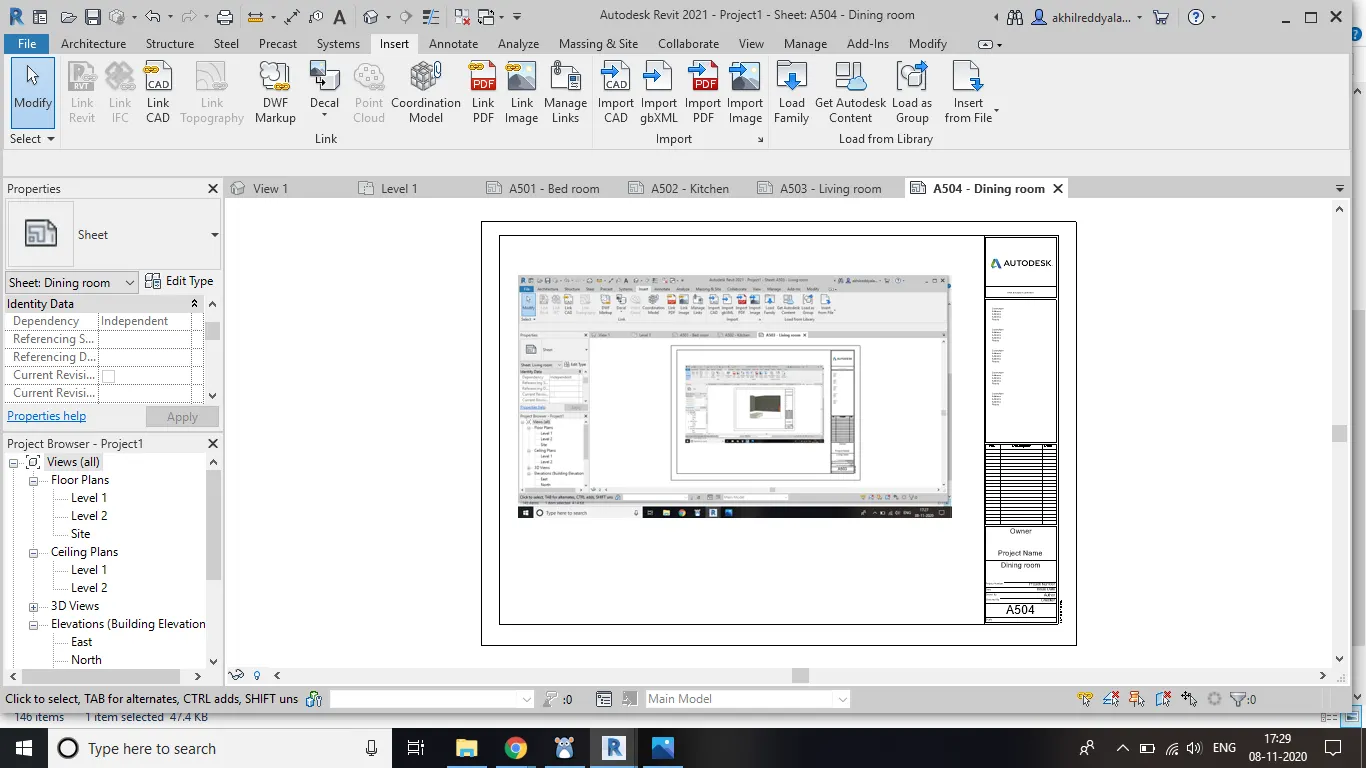
RESULT : Camera views of different rooms are attatched to different sheets.
9th Ans)
AIM : To create multiple number of sheets using sheet template.
TOOLS USED :
PROCEDURE :
a) Draw a simple 2D plan.
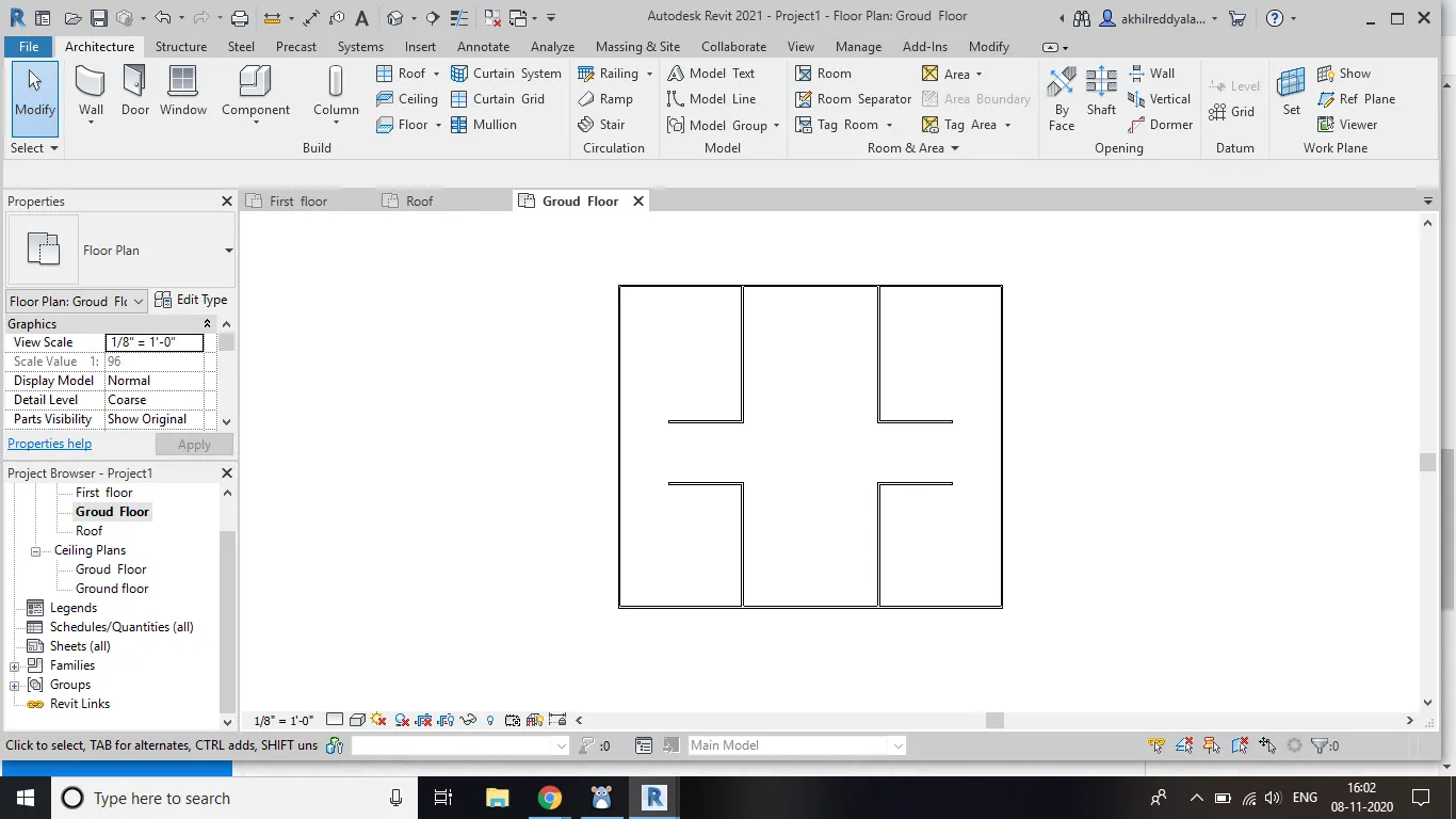
b) Go to view bar and select sheet option.
c) Rename the sheet as ground floor arhiteture plan.
d) Then load image from your device and try to paste it in the sheet.
e) Then draw an arhitetural plan for first floor.
f) Then select another sheet and rename it as A 102- First Floor Architecture Plan.
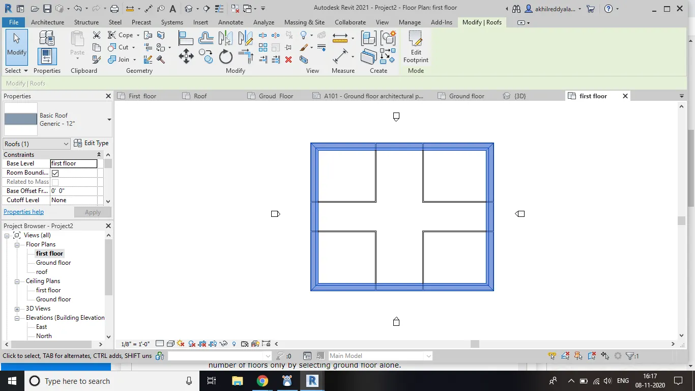
e) Select your drawing and attatch it in your sheet.
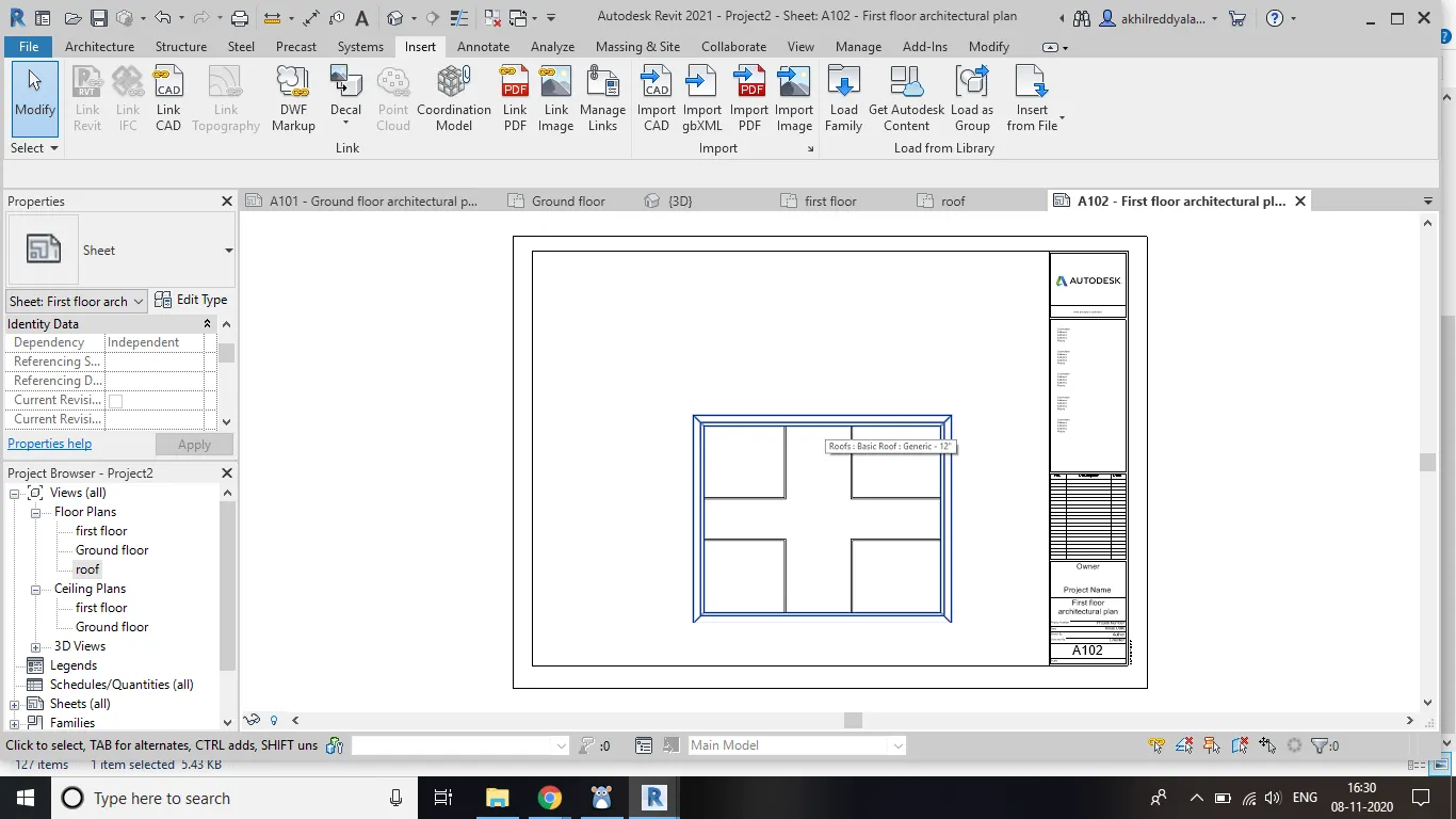
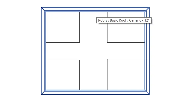
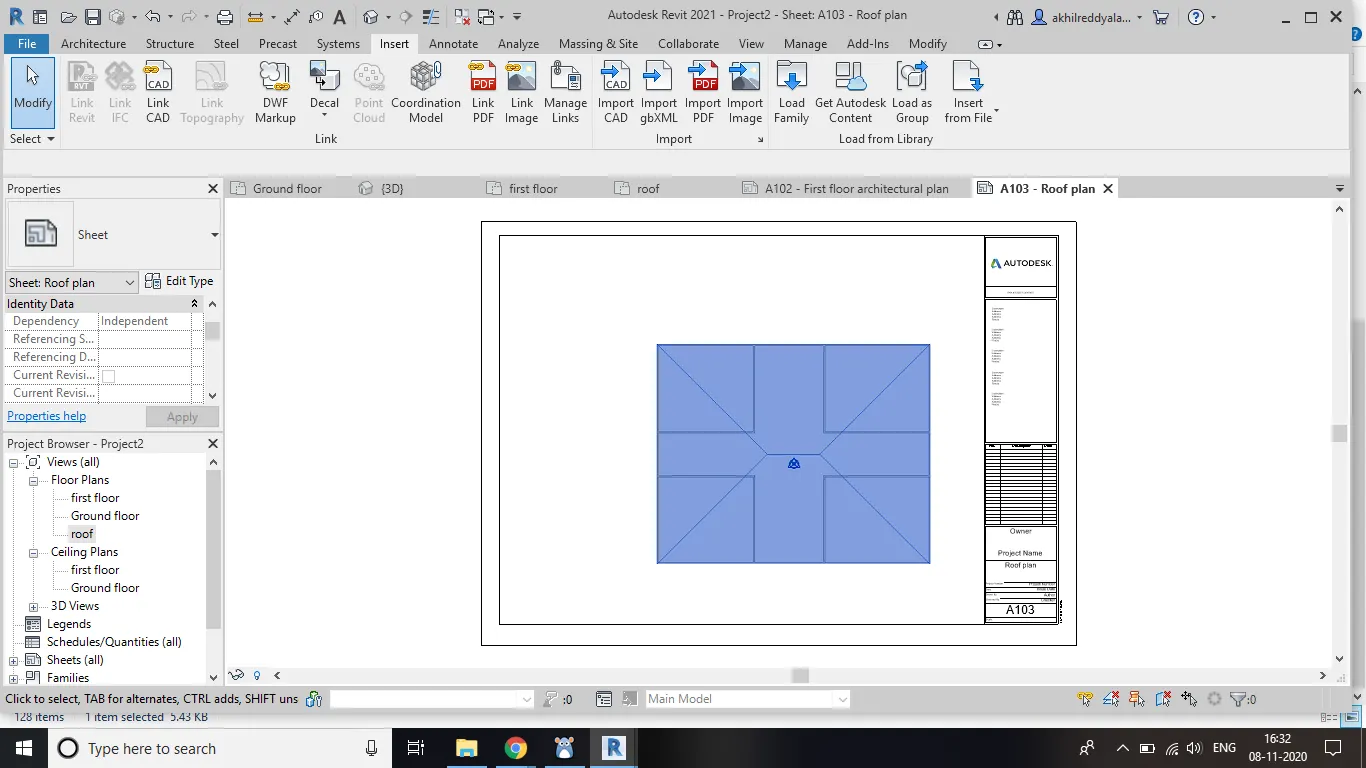
f) By using pick lines option draw a roof to your plan.
g) Load for another sheet and rename it as A103-Roof.
h) Now draw different elevations such as east , west, north and south.
i) Now create two more sheets.
j) Name one of them as east west
RESULT : Multiple number of sheets are created using sheet template.
6th Ans)
AIM :To create the elevation views, looking at your building from east, north, south and west by using elevation tab.
TOOLS USED :
PROCEDURE :
a) Draw an 2D plan.
b) Insert few rooms in it according to your convienence.
c) Now choose elevation option from view tool bar which is present at the top.
d) You can see elevation option in project browser on the left side of the screen.
e) It has further four options below it.
f) They are east , west, north and south.
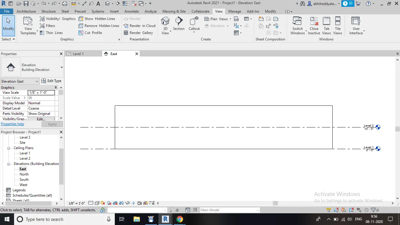
g) Now make a double click on east.
h) You can see that the plan will be elevated in an east view.
i) Take screenshot of that.
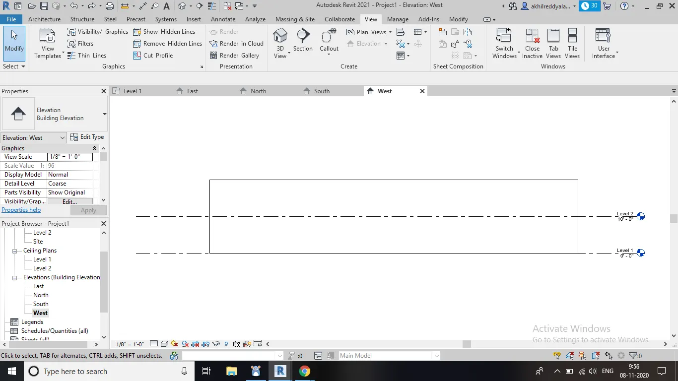
j)Now make a double click on west.
k) You can see that the plan will be elevated in the west.
l) Take screenshot of that.
m) Now make a double click on north.
n) You can see that the plan will be elevated in the north.
o) Take screenshot of that.
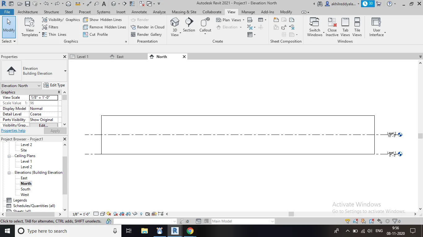
p) Now repeat the above process for south also.
q) Take the screenshot of that.
1st Ans)
AIM : To prepare a model and attatch ceiling to it.
TOOLS USED :
Wall
ceiling
Pick lines
PROCEDURE :
a) Draw a 2D plan using wall command.
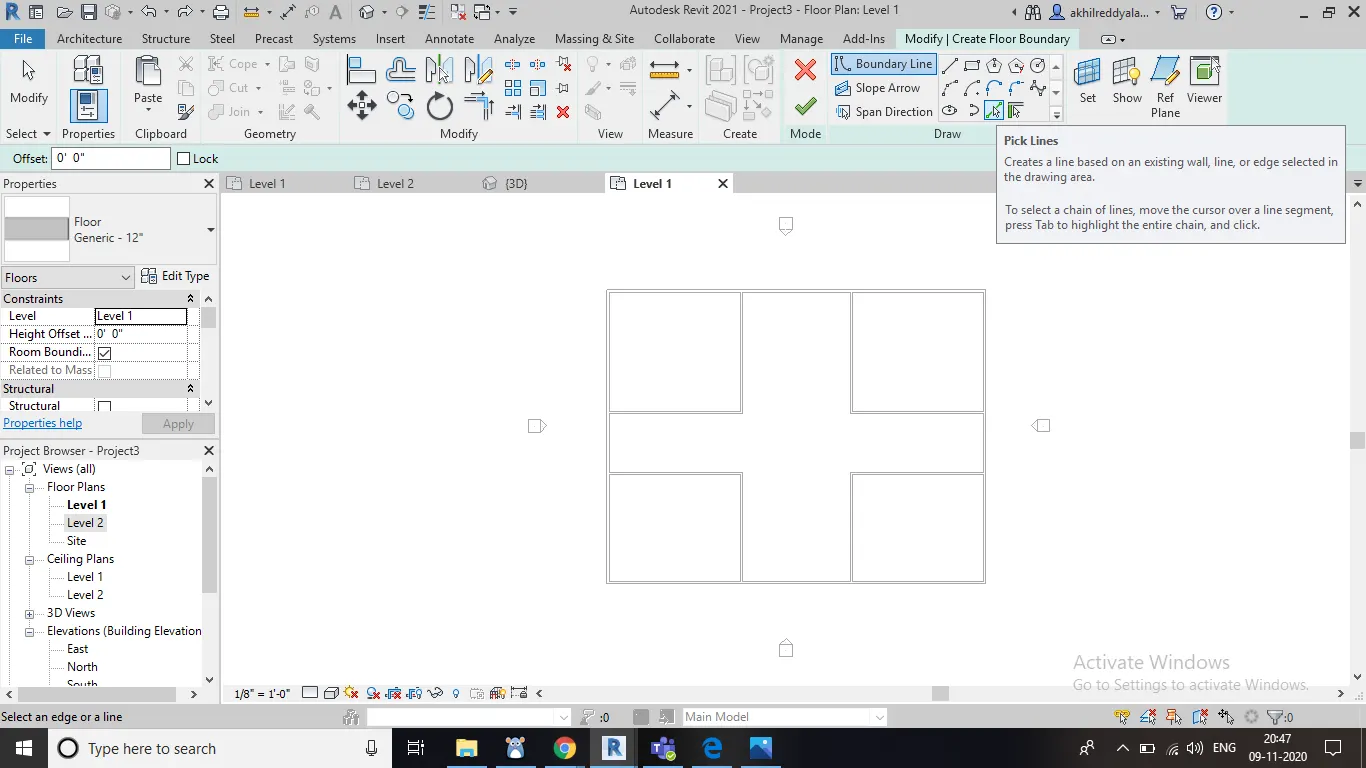
b) Select level 2 and draw another plan there.
c) After drawing level 2 , view the diagram in 3D view.
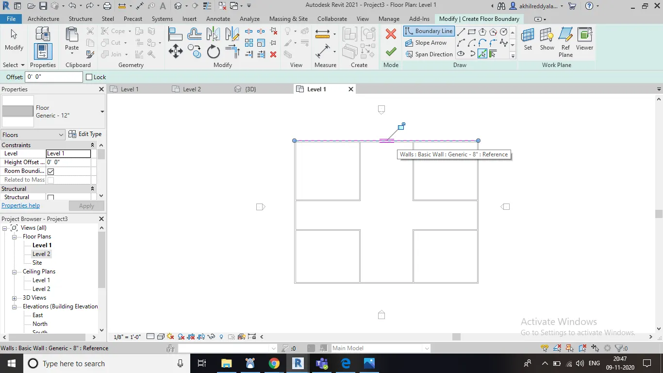
d) Select celing option in top menu bar.
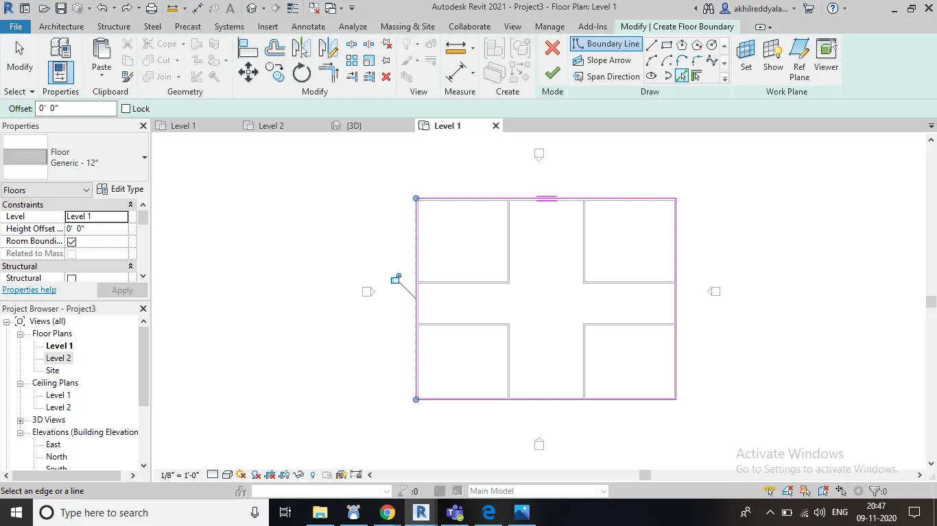
e) Then two options will appear on the right side.
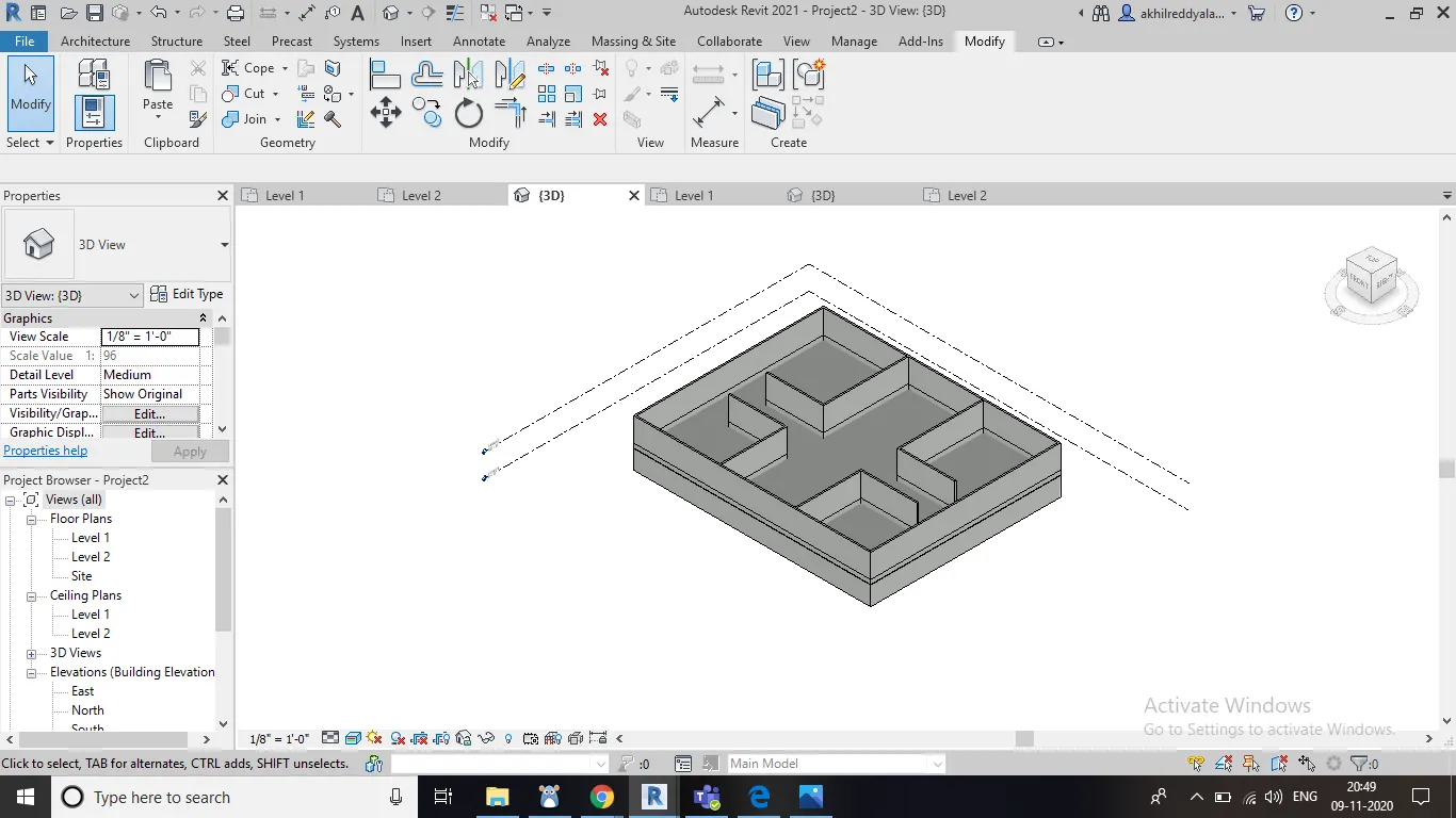
f) From those two select sketch ceiling.
g) Then select pick lines option and select all external lines in your plan.
h) After that click on yes option in the top which will be in green colour.
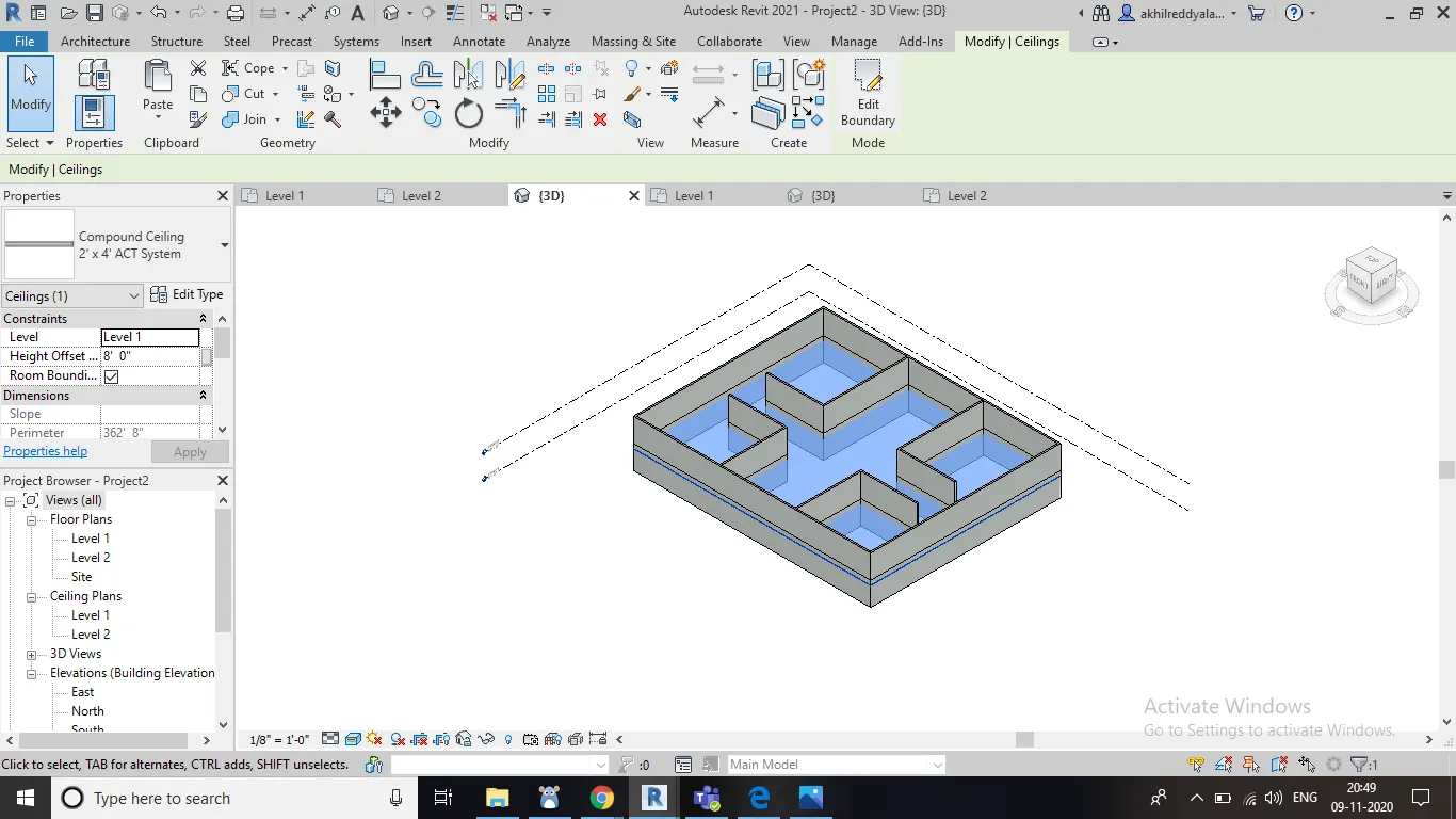
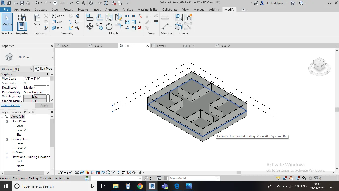
i) After that select ceiling layer from 3D view you will get an ceiling option.
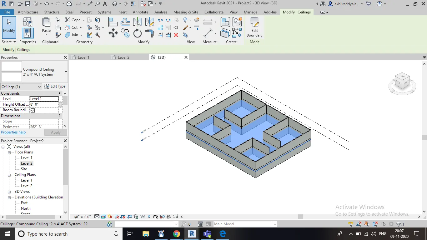
j) Ceiling will be done for your diagram.
k) Take screenshots of each and every step.
RESULT : Ceiling was done to our building successfully.
3rd Ans)
AIM : To create plan views for ground floor level and first floor level including all the walls , floors and components.
TOOLS USED :
View
plan view
floor plan
components
wall
PROEDURE :
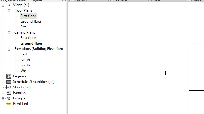
a) Click on view in the menu bar.
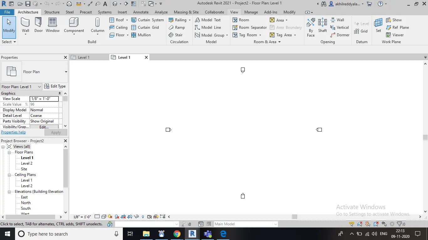
b) Then a new tool bar opens.
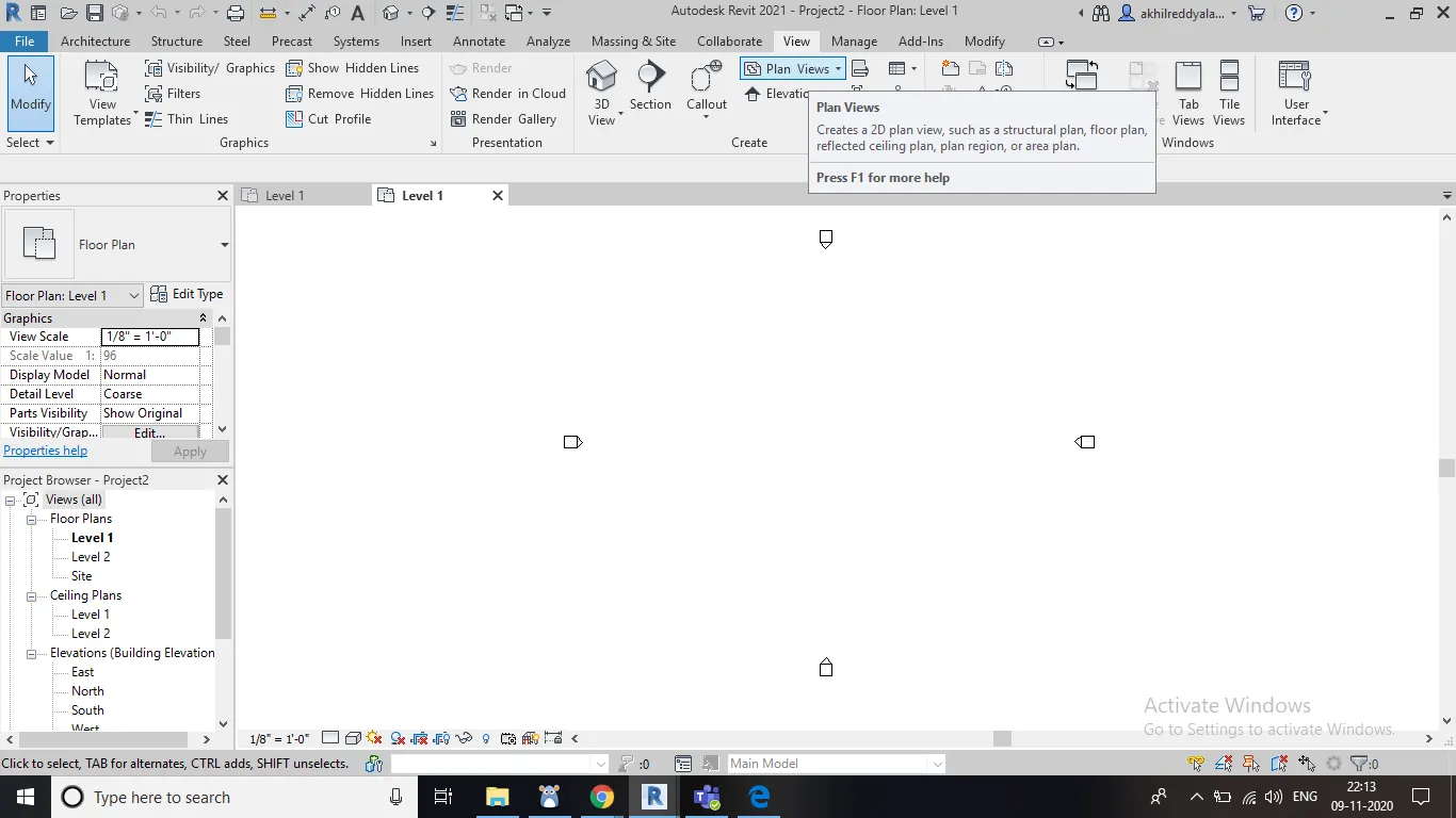
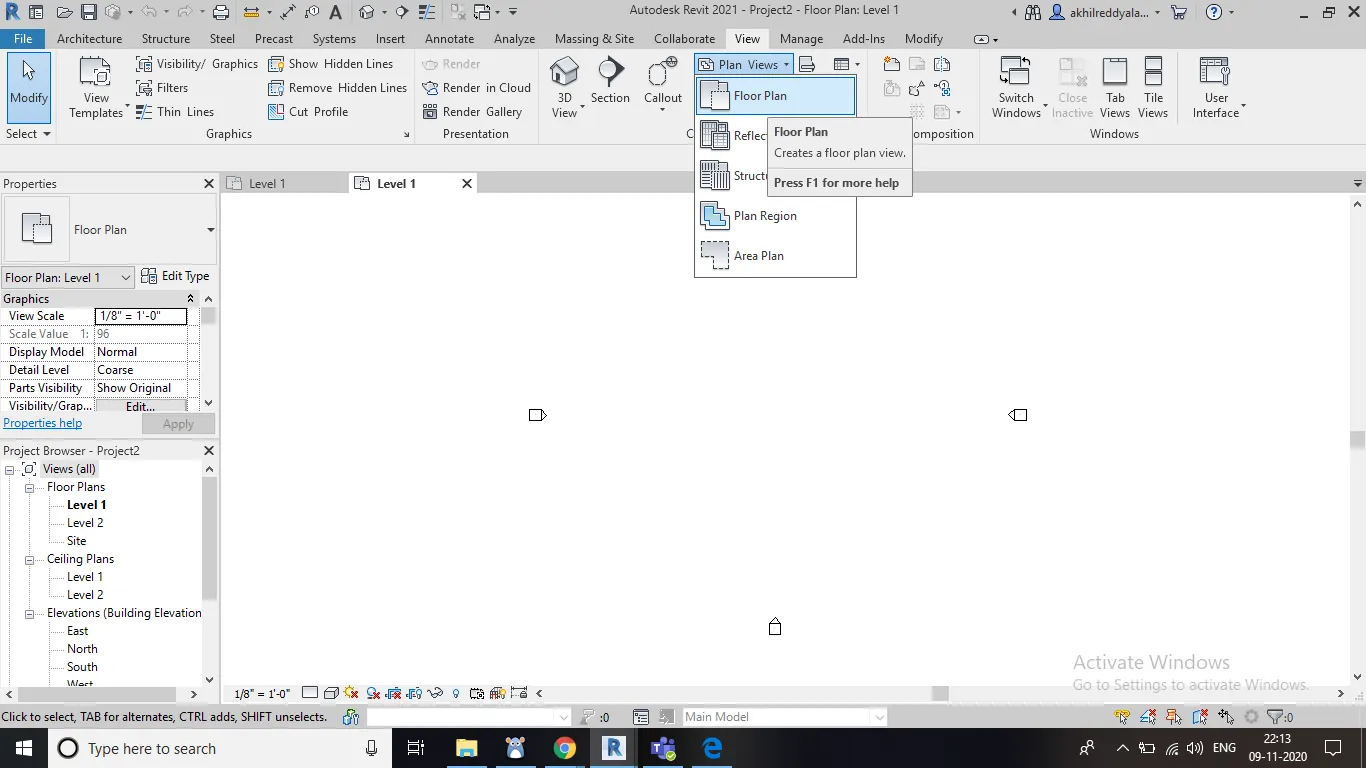
c) From that select plan views.
d) Further select floor plan from that.
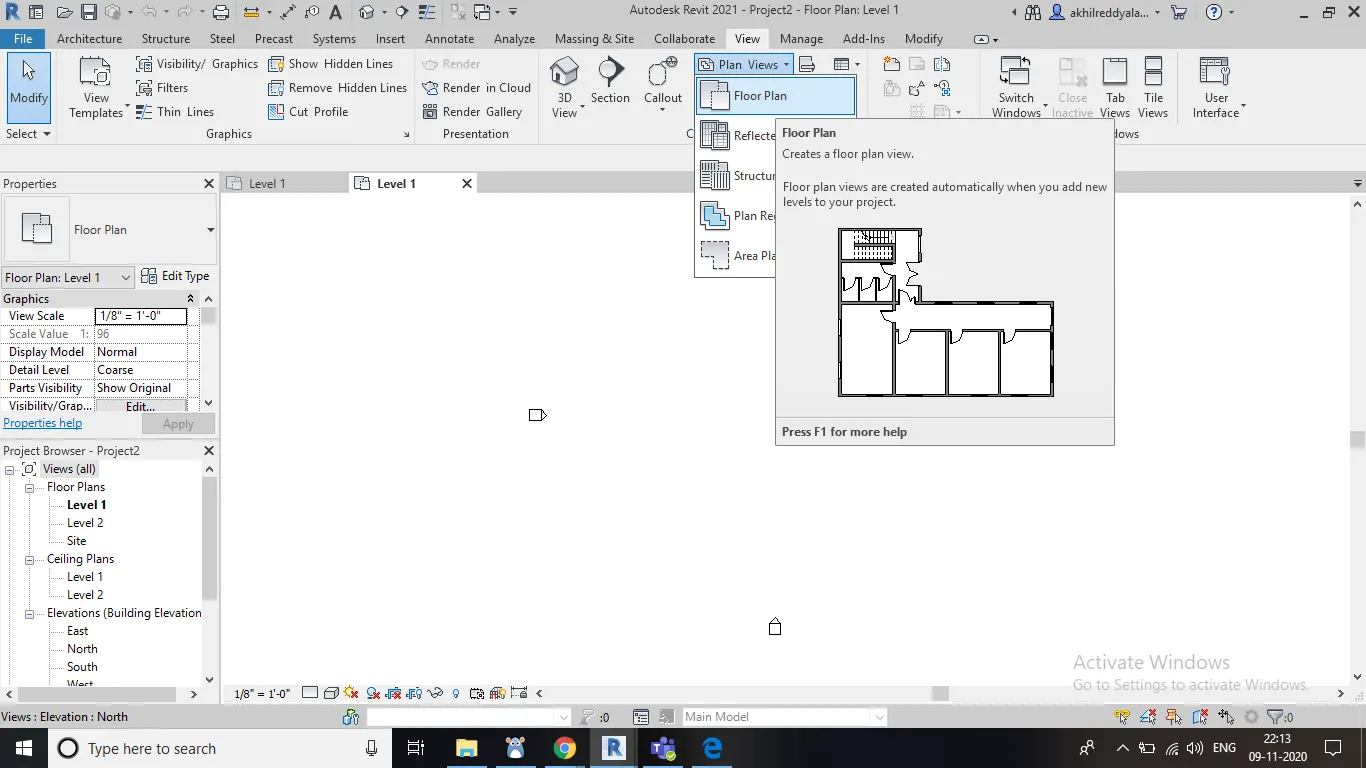
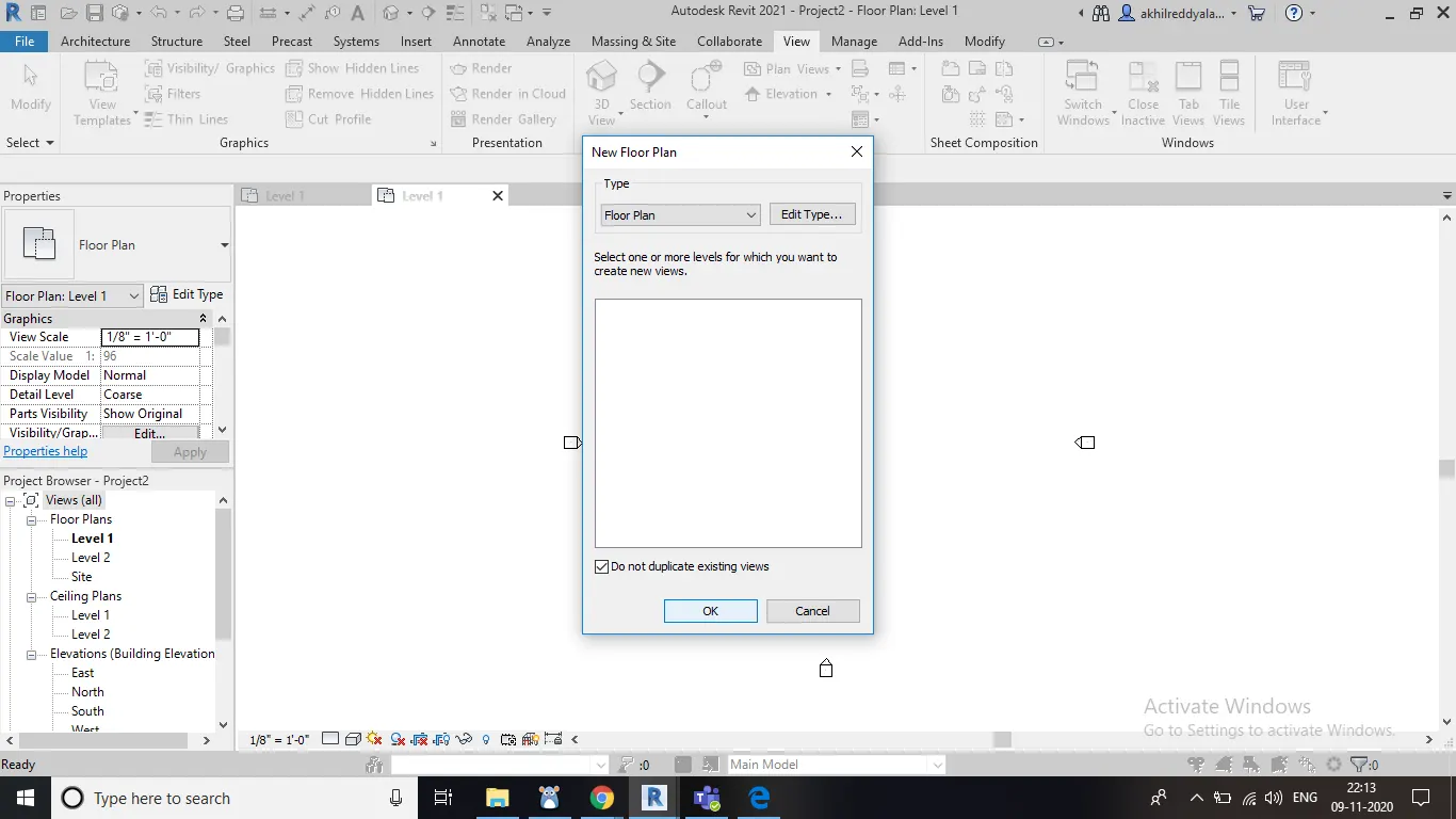
e) A tool bar opens and click 'OK' in that.
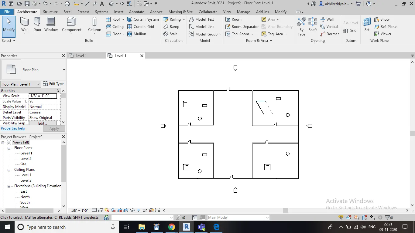
f) Level 1 opens . Draw an plan and place rooms and few components in it
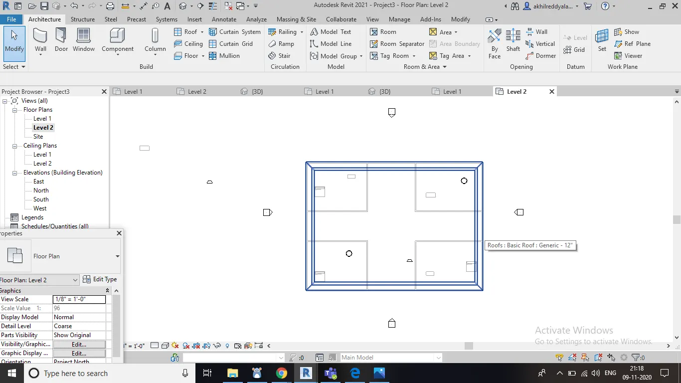
g) Open level 2 and draw another plan and divide it into rooms.
h) Place few components in those rooms.
i) Take screenshots of those plan views.
RESULT : Floors are drawn in plan views successfully.
"Structure plans and structure templates were not covered in the videos of starting 4 weeks."
2nd Ans)
AIM : To create a model roof and adjust the slope of the roof.
TOOLS USED :
Wall
Line
pick lines
roof
units
PROCEDURE :
a) Draw a floor plan in level 1.
b) Load level 2 to create roof.
c) Select roof option from menu bar.
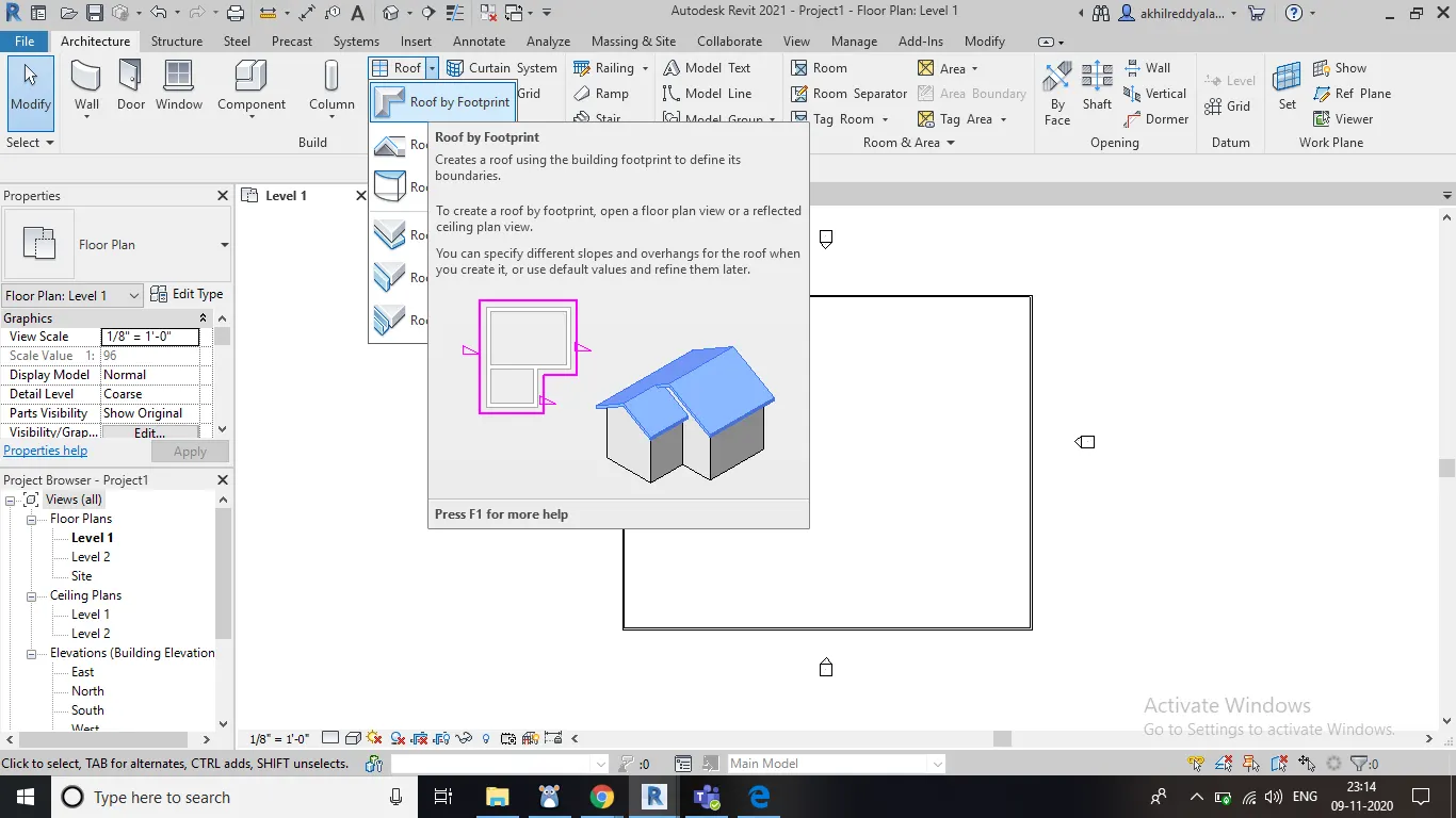
d) Select roof by foot print.
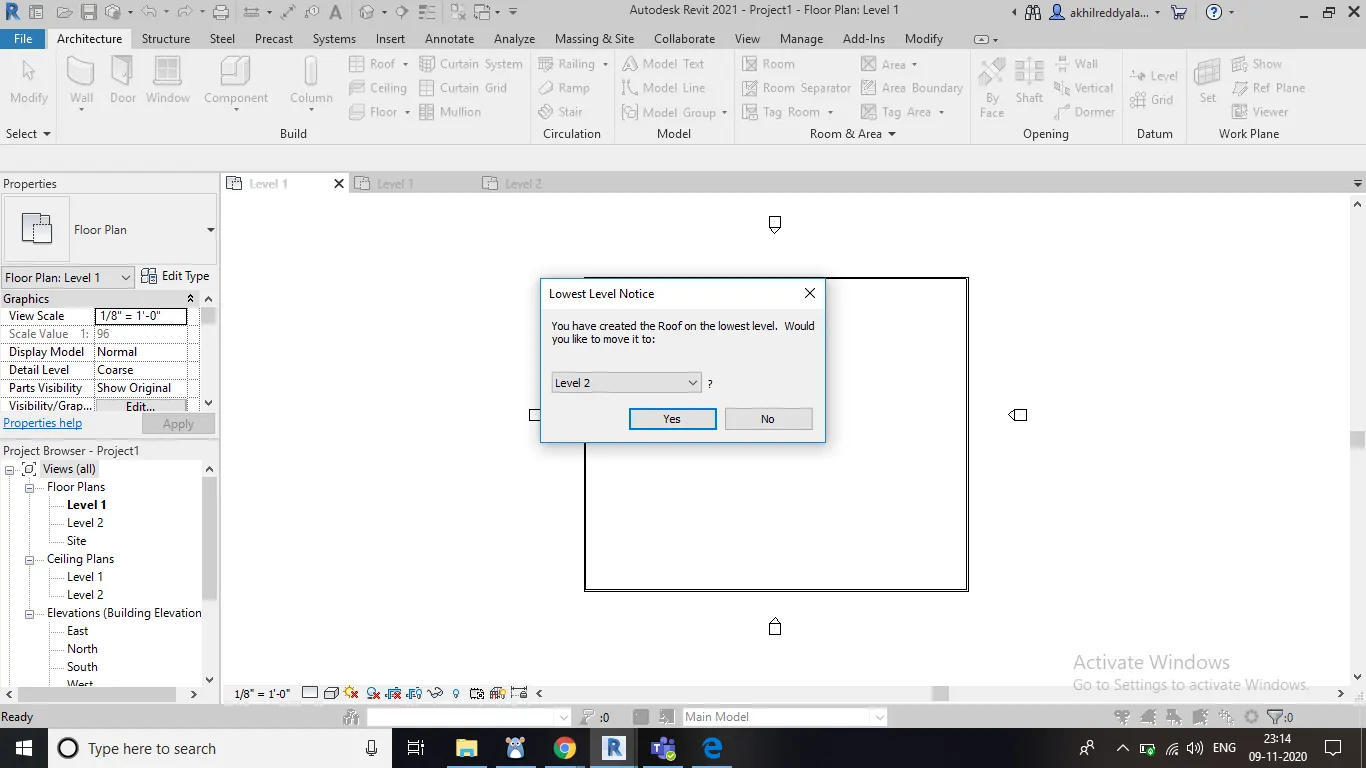
e) Use pick lines to select eternal walls.
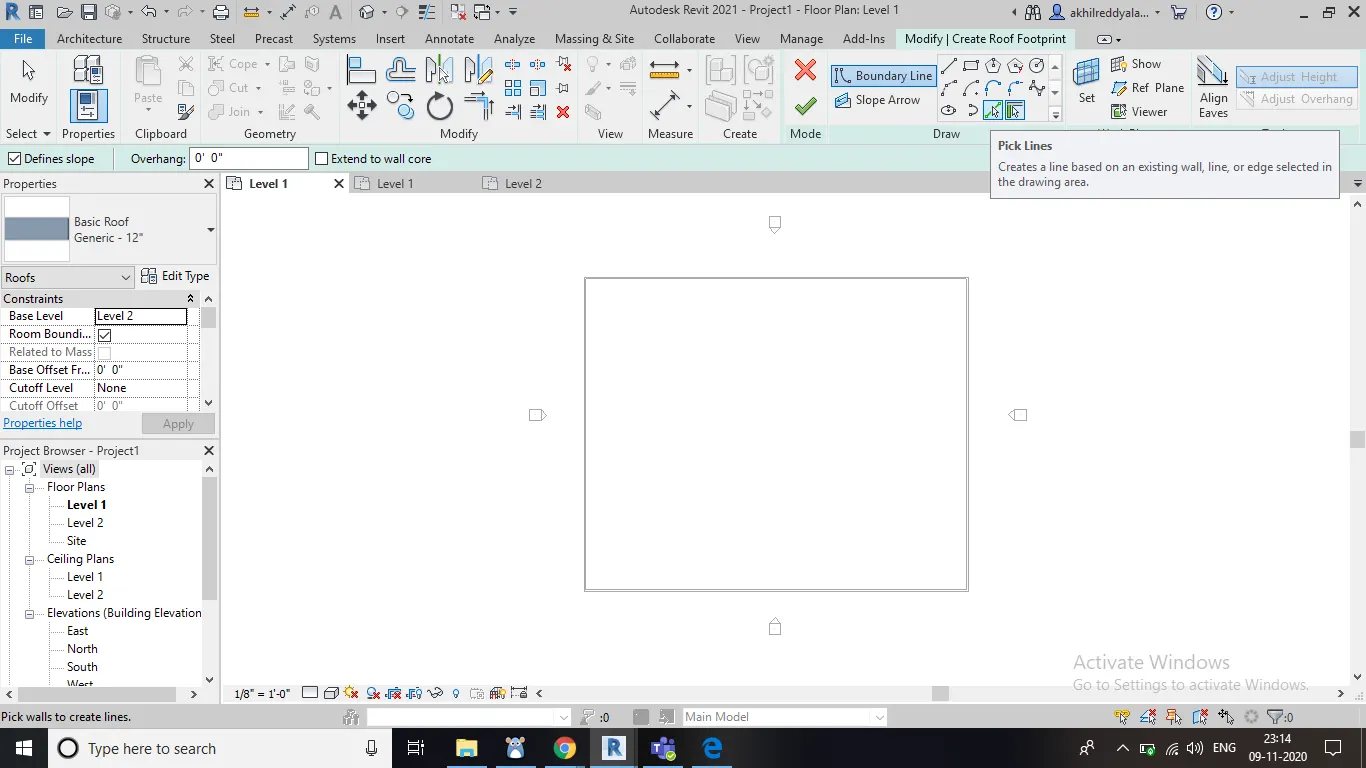
f) After that click on option yes which is present in green colour on the top.
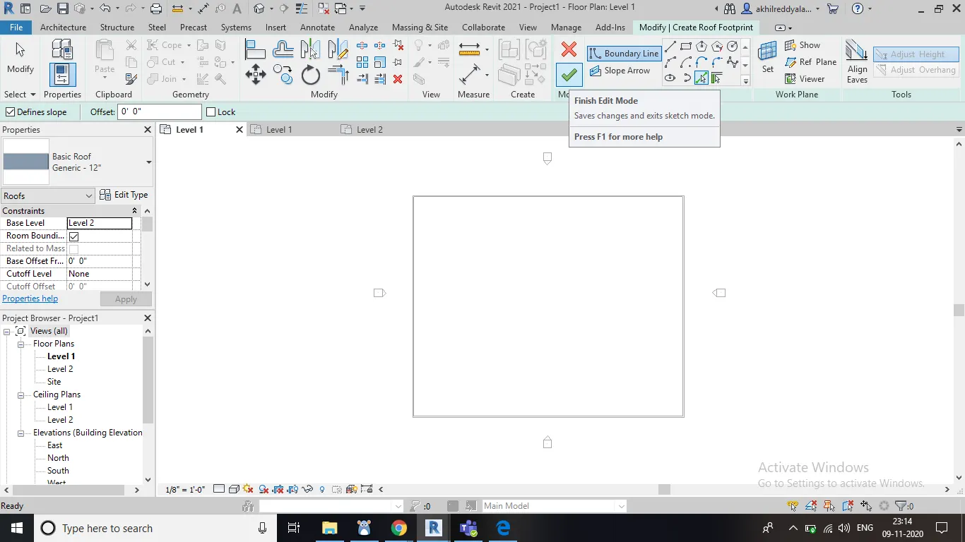
g) Now the roof will be created.
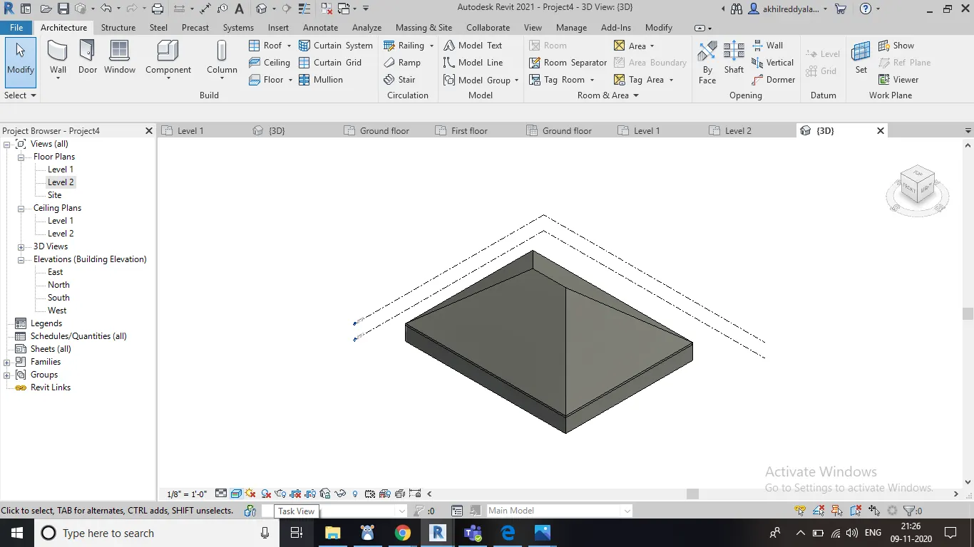
h) Now we need to adjust the slope of the roof to 10 degrees.
i) Go to units.
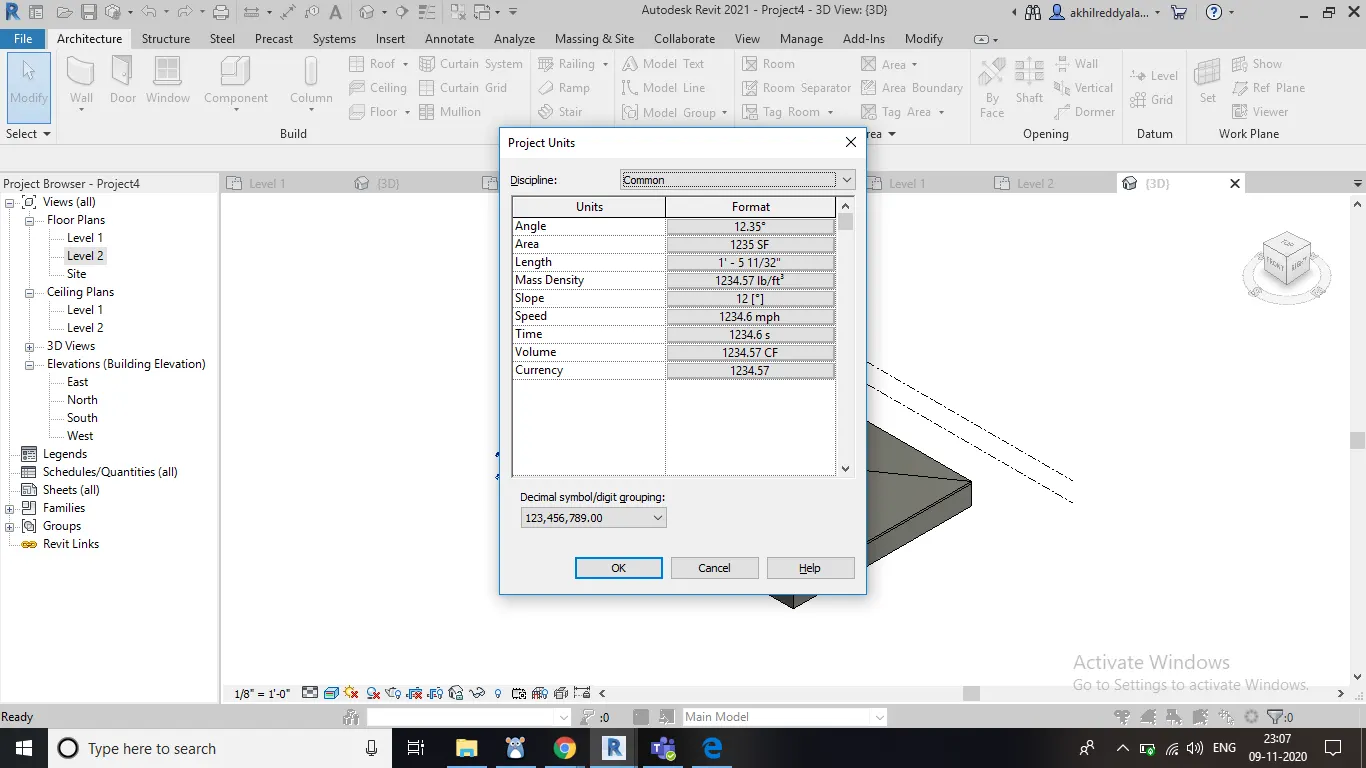
j) Change it to slope.
k) Set units units as degrees.
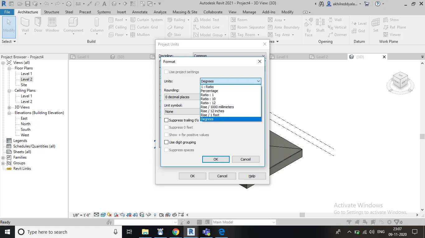
l) Go to project browser and make the slope as 10 degrees.
m) New roof of 10 degree slope is obtained.
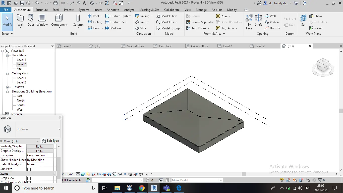
RESULT : Therefore new roof is created and slope of the roof is adjusted to 10 degrees successfully.