Week 1 Challenge
1st Ans) AIM : To create a file and naming it in Revit.
TOOLS/COMMANDS REQUIRED :
File menu
open
PROCEDURE :
a) After opening autodesk revit icon , u can find a folder named 'FILE' on top
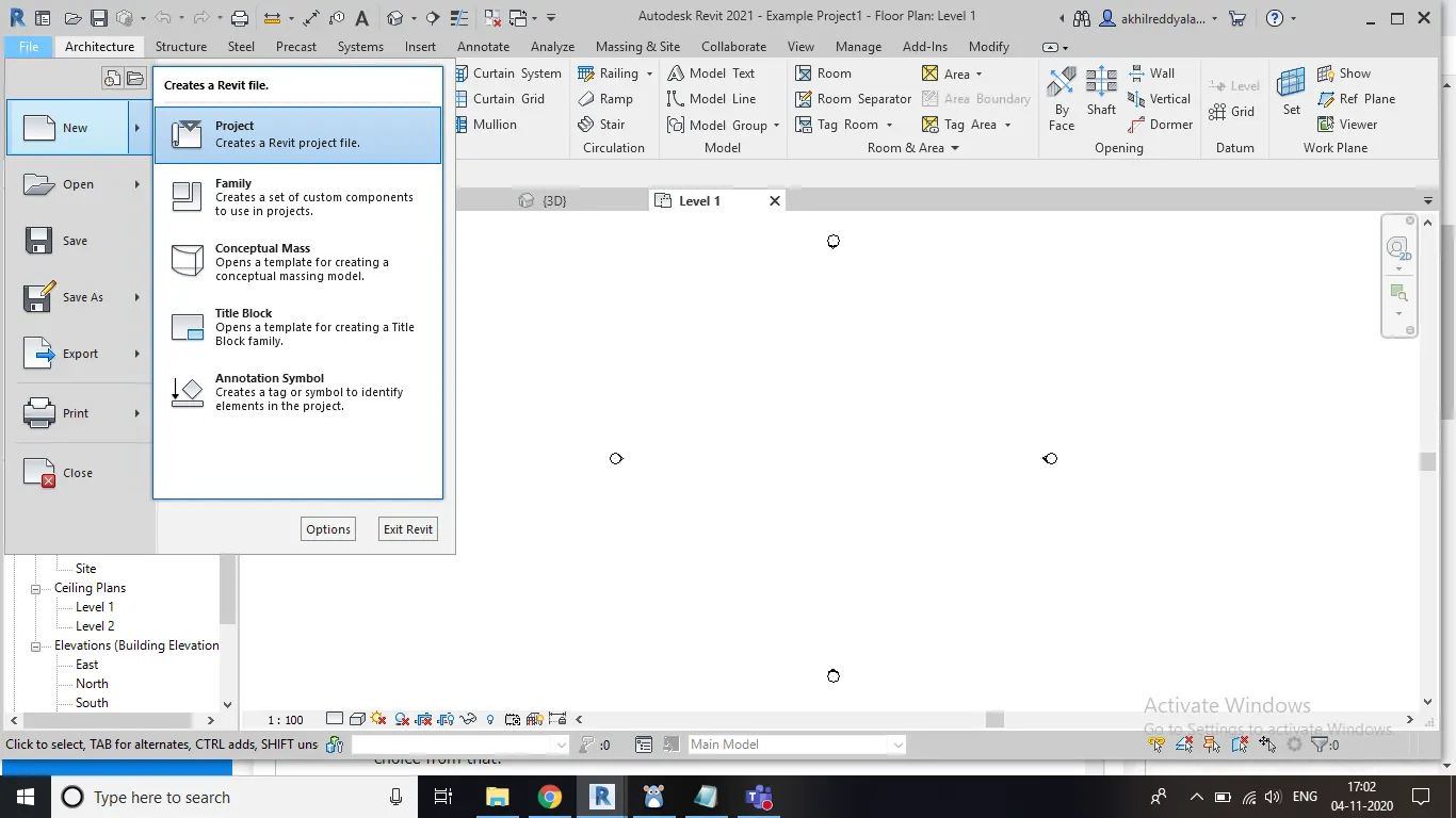
b)After that different options will appear by that side. Select 'NEW' in that.
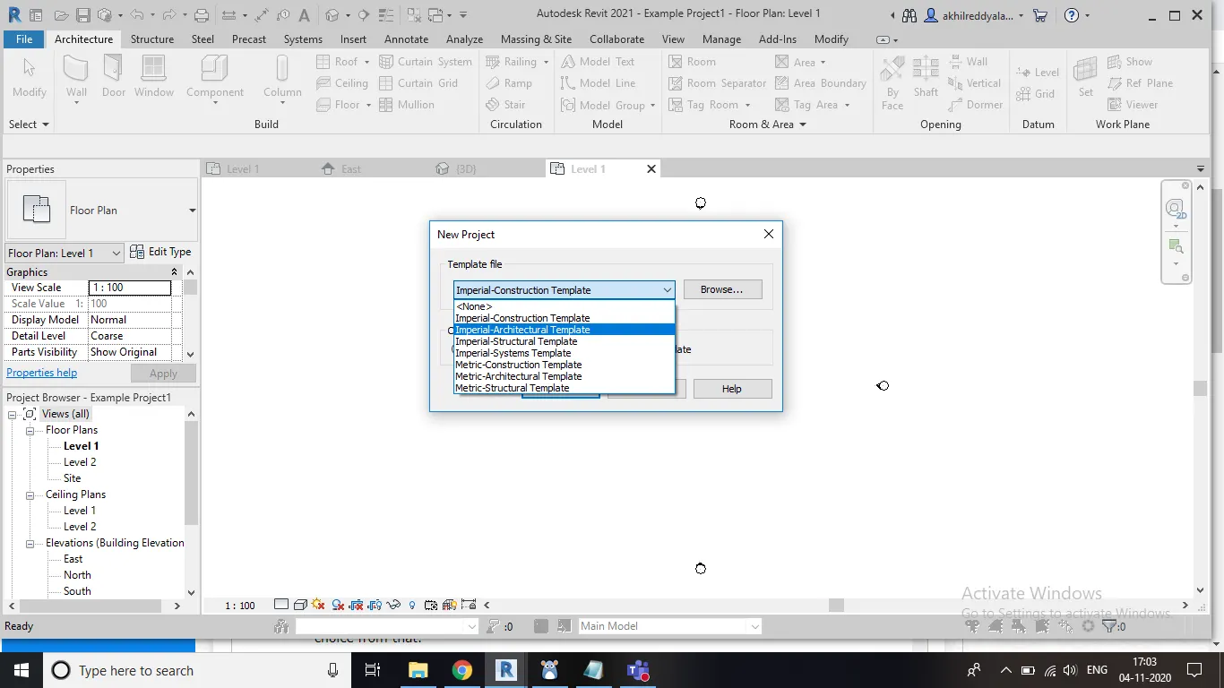
c) Then you will find different types of projects like architecture , structural etc..Select your choice from that.
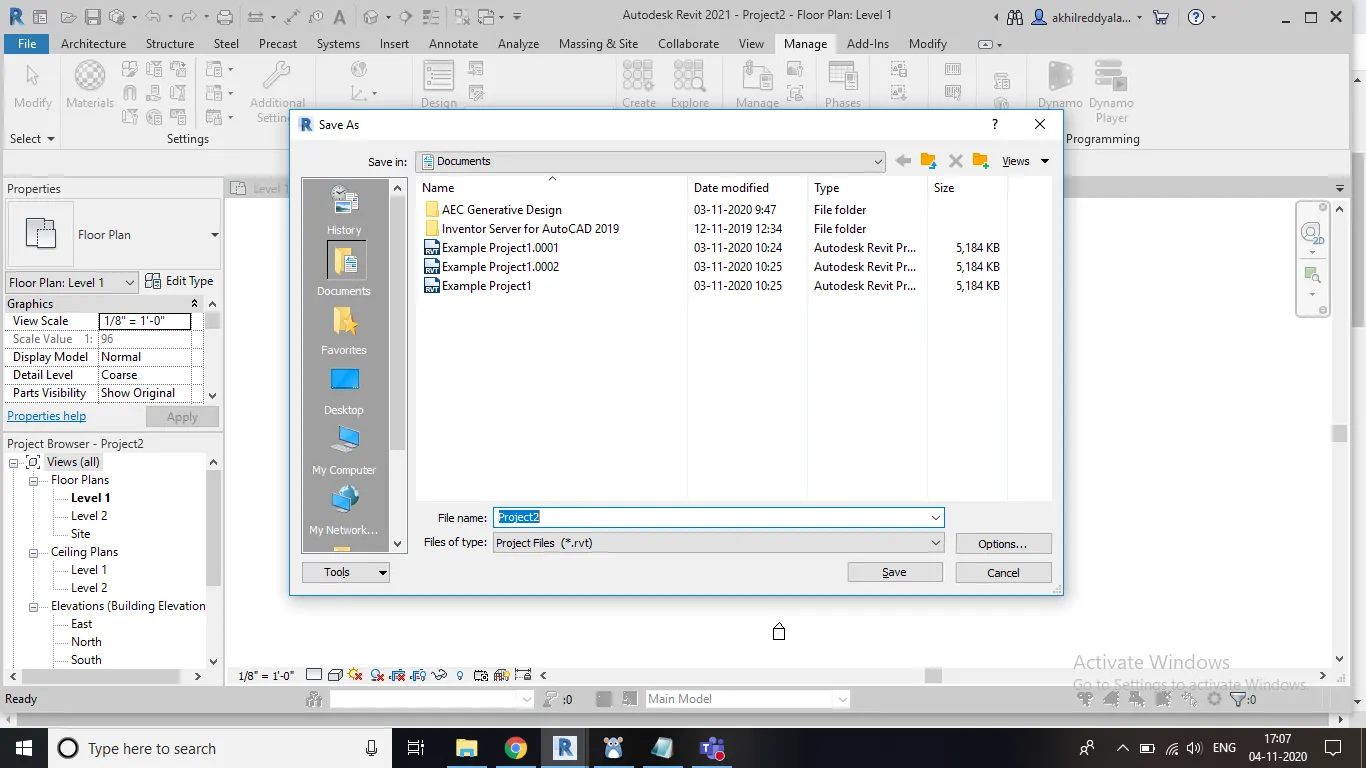
d)After that you can give name to your project of your choice.
RESULT : we created a file and named it.
2nd Ans) AIM : To save the new project file & close and open using icons from file toolbar.
TOOLS/COMMANDS USED:
File
Save as
Name the file
PROCEURE:
a)In the top menu bar you can find save option.
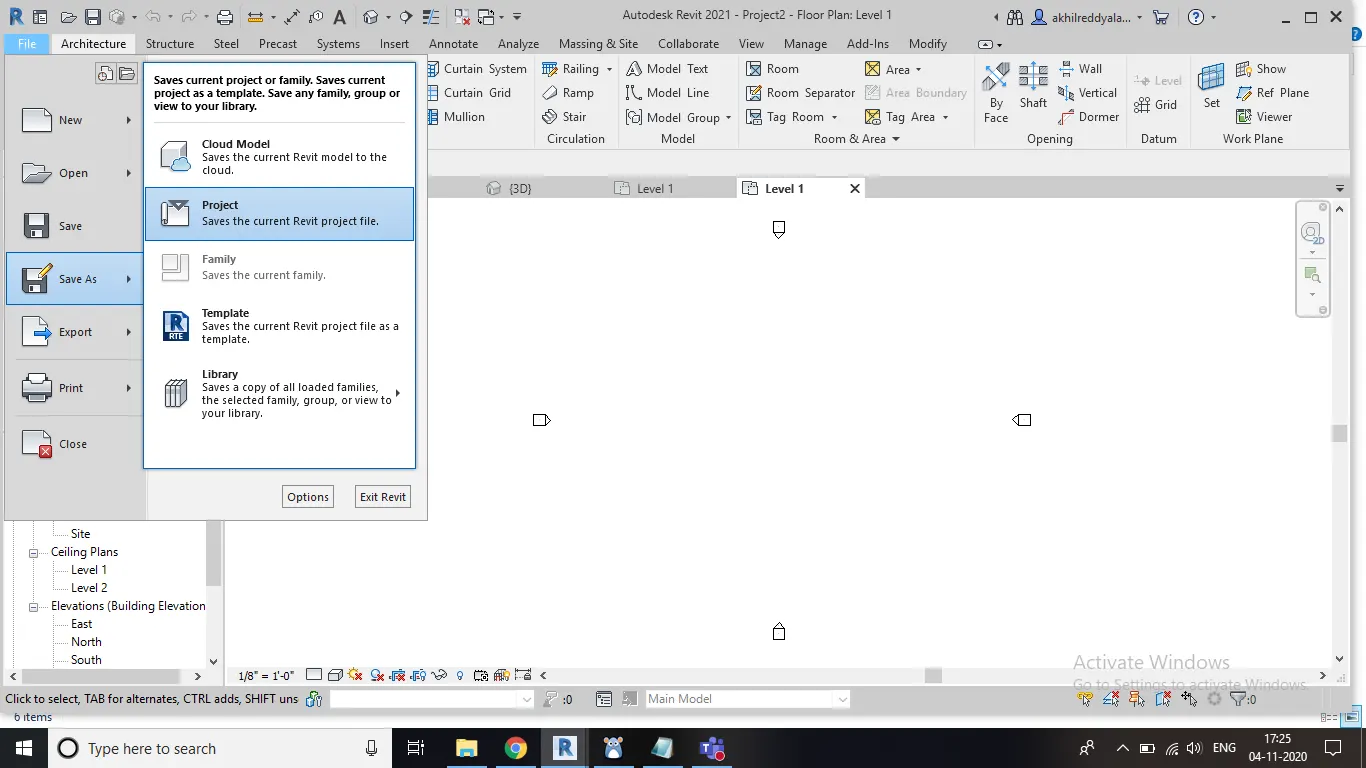
b) After clicking save , it will you different options such as documents , files , folders etc.
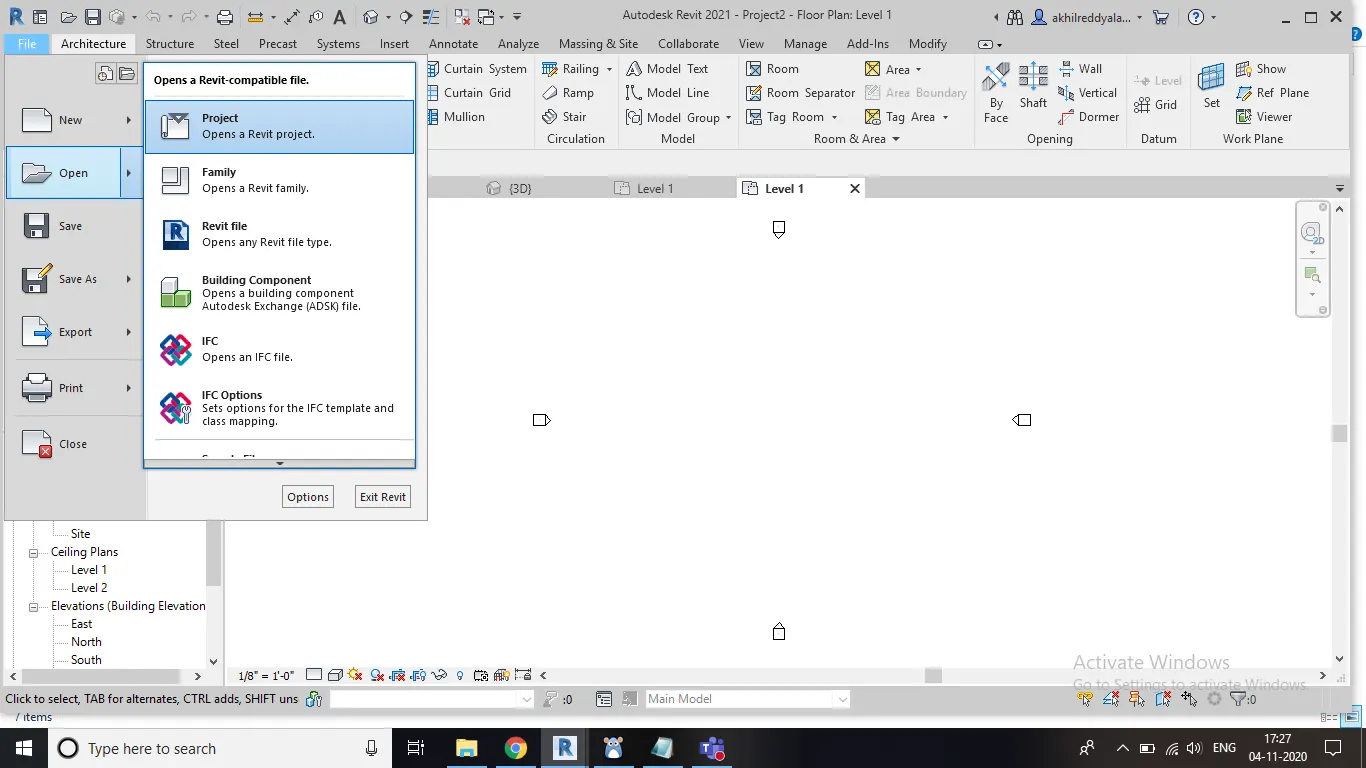
c) Select a place of your choice and name it.
RESULT :We have saved new project file.
3rd Ans) AIM : To create a rectangular layout of walls of about 40’-0” X 35’-0”
TOOLS/COMMANDS USED:
Architecture
wall
PROCEDURE:
a)Select architecture template . After that from wall menu select architectural point type.
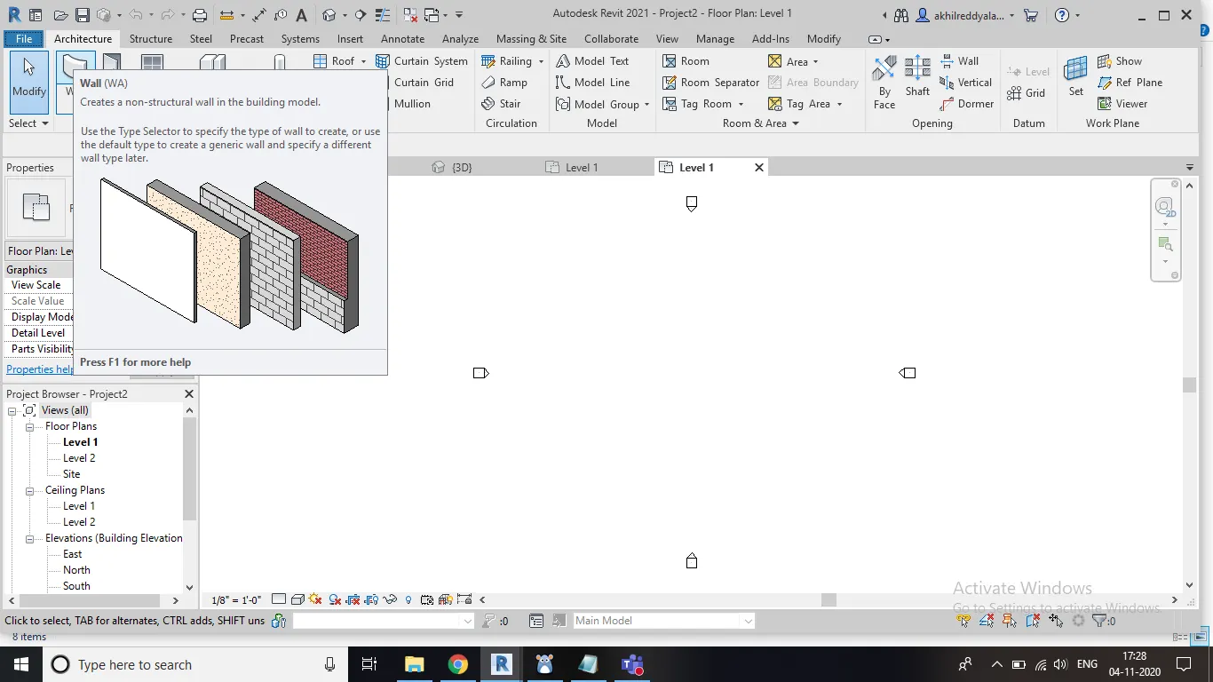
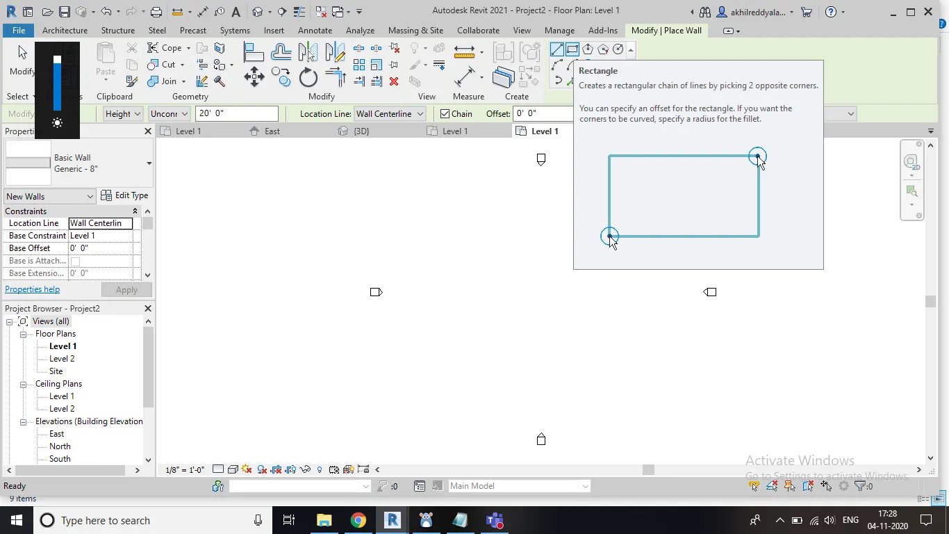
b)Draw rectangle by selecting rectangular icon.
c)Change the dimensions of that rectangle into given dimensions (40 x 35)
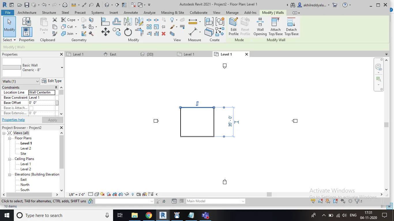
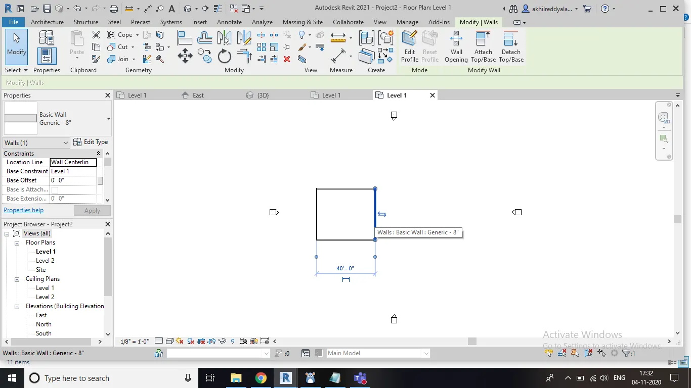
RESULT : A wall of 40 x 35 is created.
4th Ans) AIM : To add dimensions to the layout from Annotate tool bar use aligned option.
TOOLS/COMMANDS USED :
annotate
aligned
PROCEDURE:
a) Initially draw a wall.
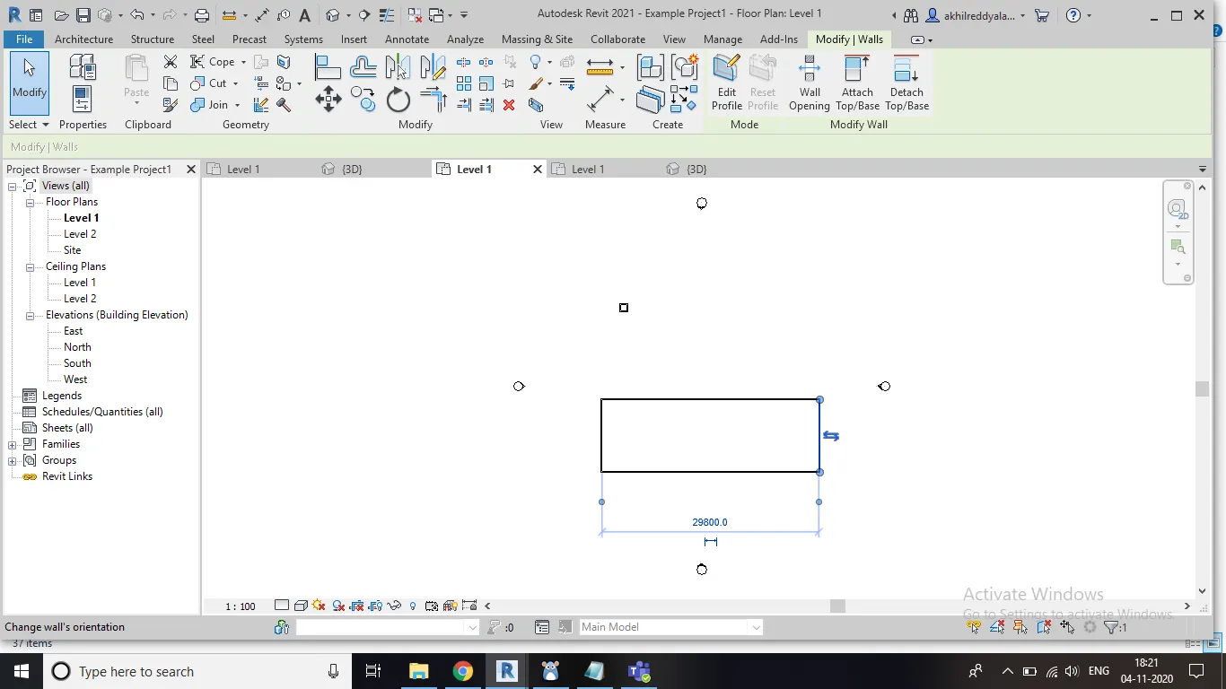
b)Click on annotate option and choose aligned option. Now dimension of that wall will be visible.
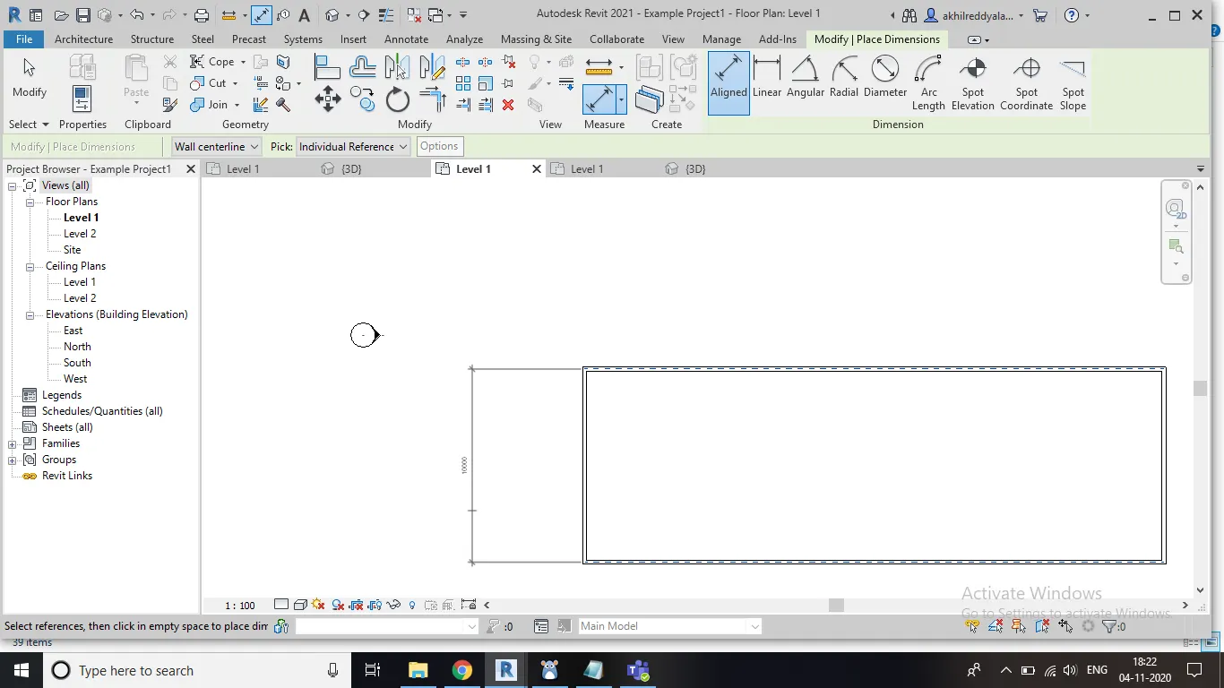
RESULT : Dimensions are added by using annotate tool bar.
5th Ans) AIM : To create a 3D view from the view tool bar and save the view with appropriate name.
TOOLS/COMMANDS USED :
Architecture template
Wall
Template
PROCEDURE :
a)Select architecture template and select wall command.
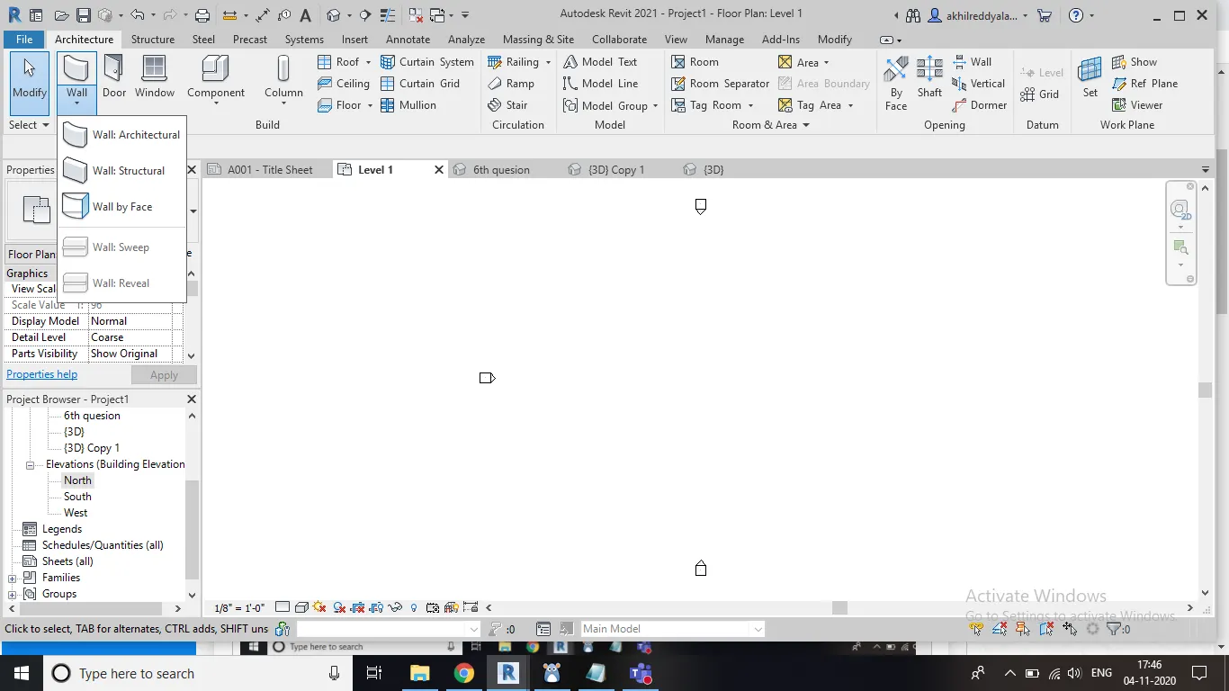
b)Then you will find a drop down menu beside generic wall.
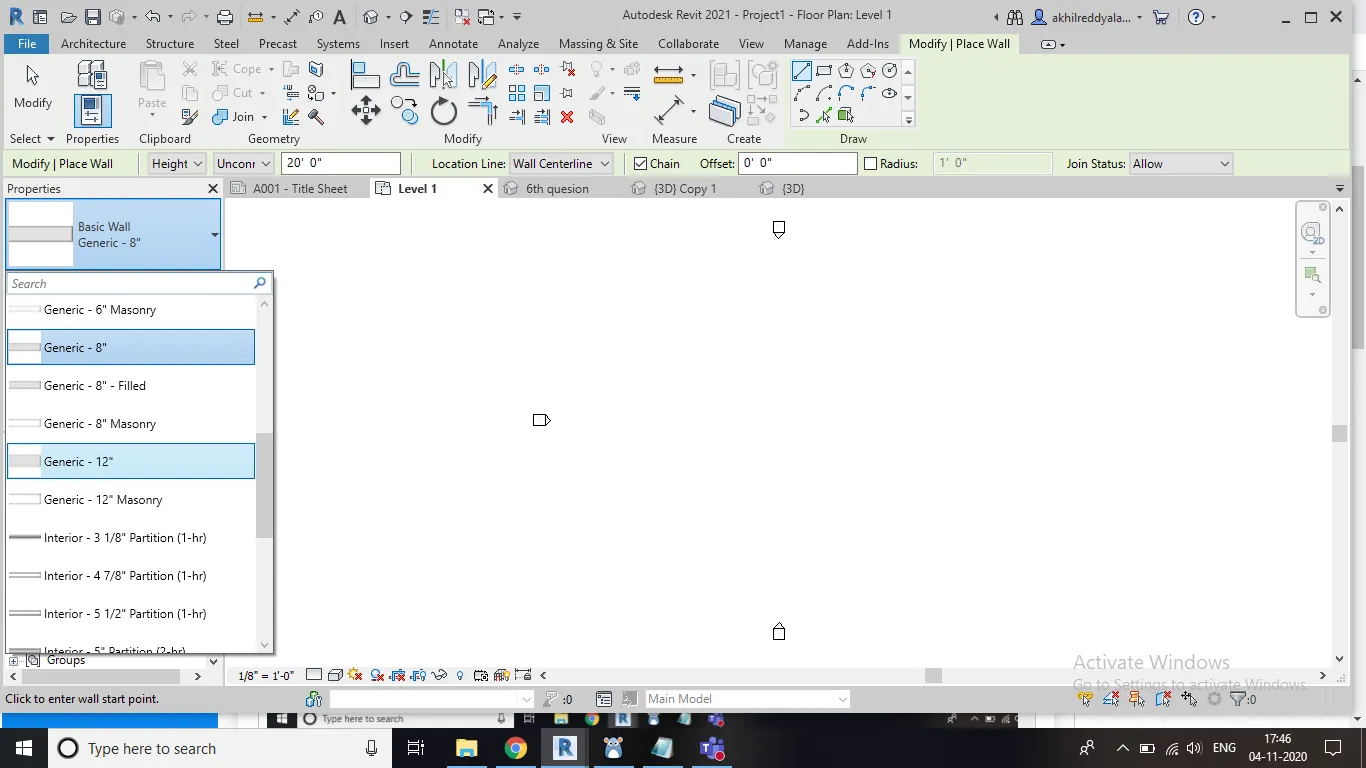
c)There you will find different types of walls like curtain walls ,stacked walls etc....select your choice from that.
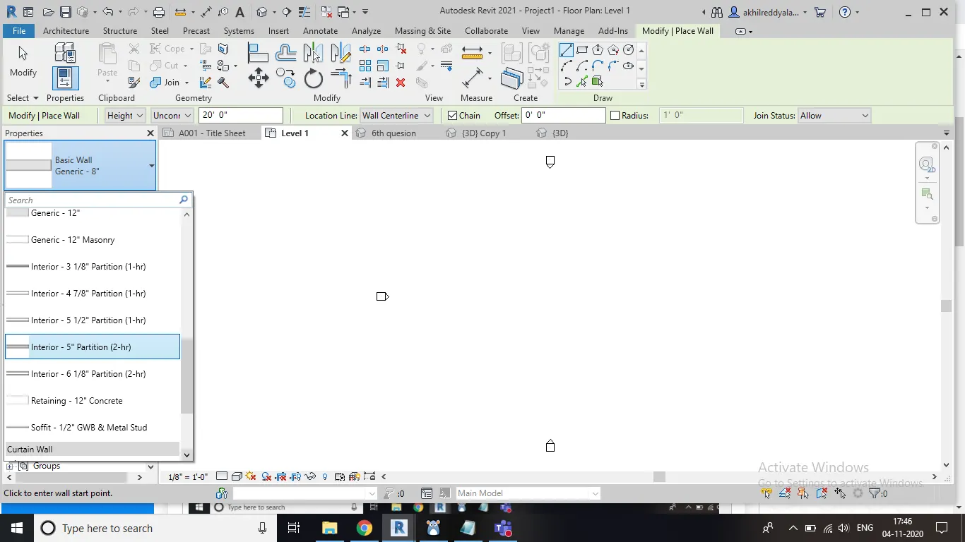
RESULT : Different walls are shown by using property browser.
6th Ans)
AIM : To create a 3D view from the view tool bar and save that view with appropriate name.
TOOLS/COMMANDS:
view
3D
save
rename
PROCEDURE :
a) Draw a wall of your own dimensions.
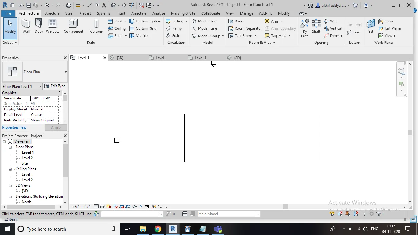
b) Click view tool bar , then you will get 3D option.
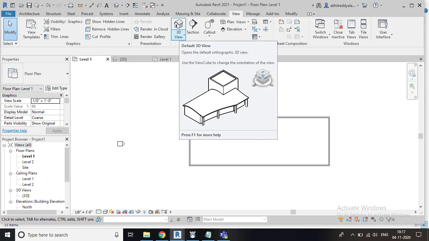
c) By clicking 3D option your drawing gets converted into 3D.
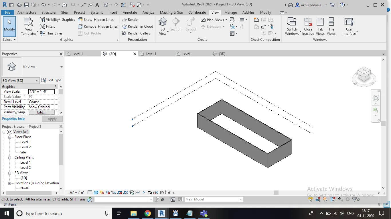
d) Then double click on 3D in project browser.
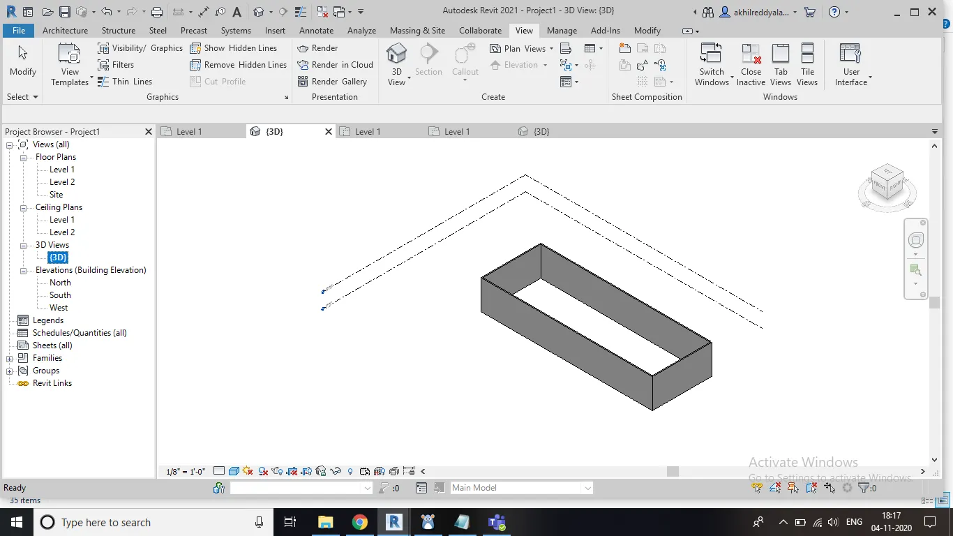
e) Then you can rename it.
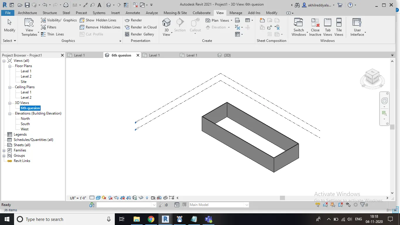
RESULT: We have created a 3D view and renamed it successfully.
7th Ans)
AIM : To navigate through the 3D model using view cube.
TOOLS/COMMANDS USED :
Navigation wheel
PROCEDURE :
a) Create a 3D of any shape like rectangle.
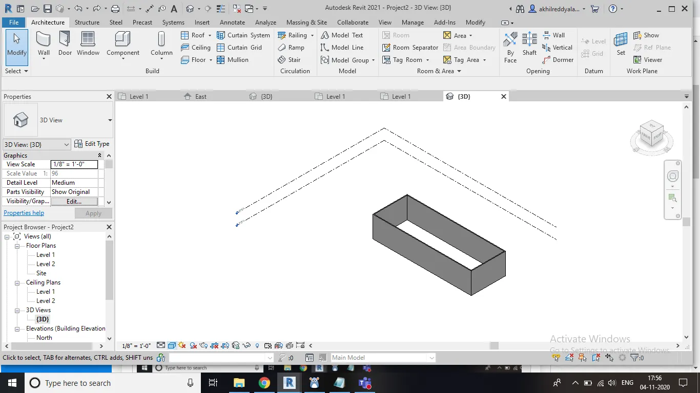
b) On the top right corner you can find a cube symbol.
c) You can find different views such as front view , top view , right side , left view, back view and
bottom view.
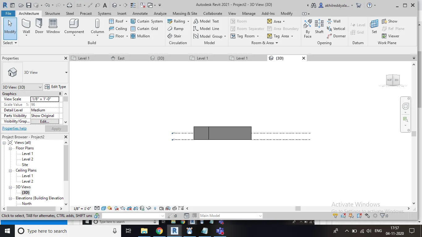
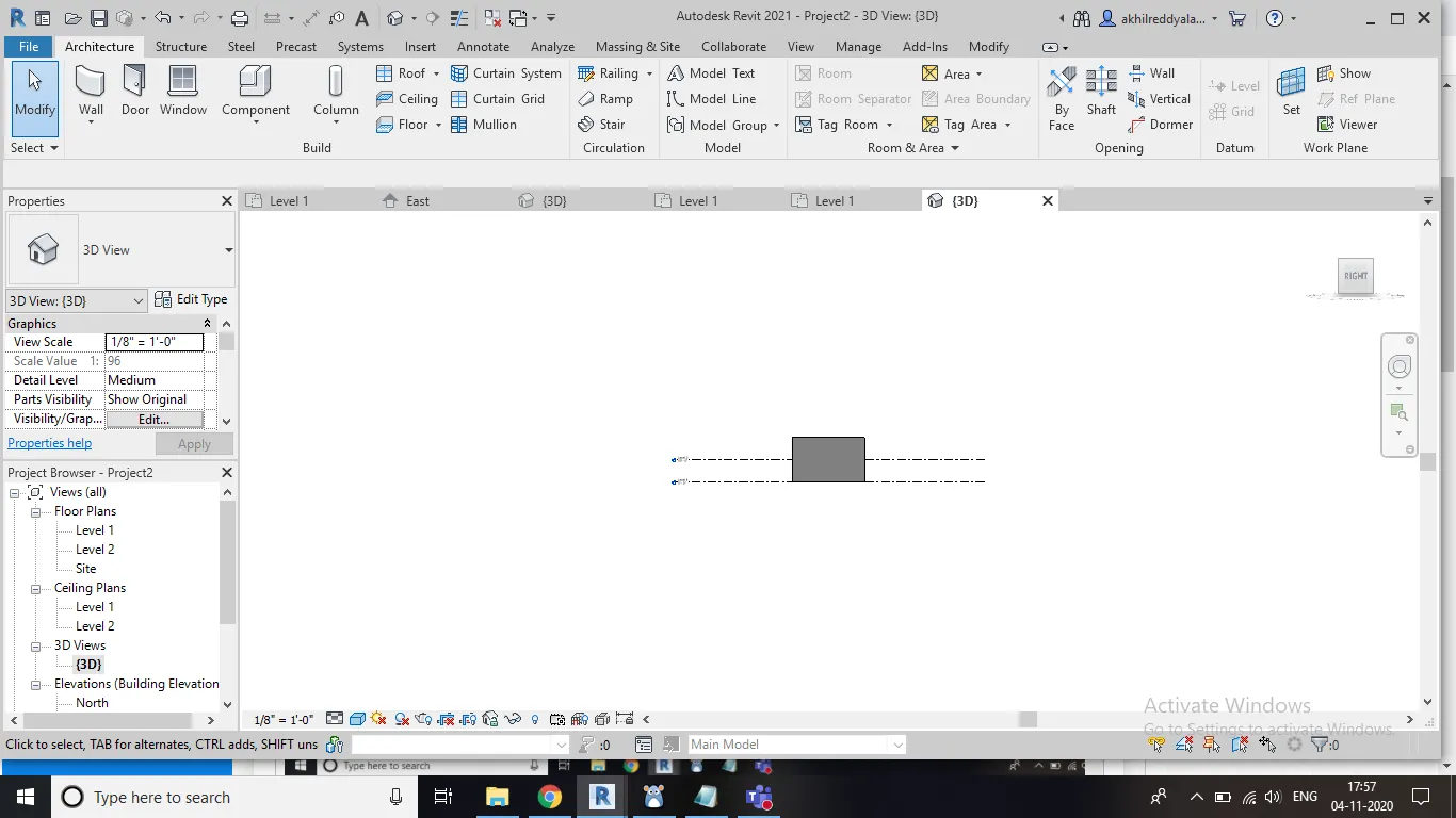
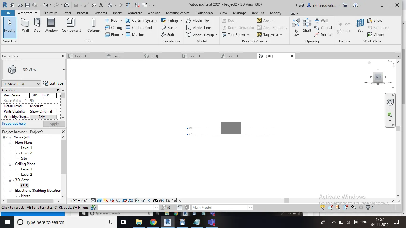
d) You can get whatever view you want.
e) Pan is used to rotate the diagram.
f) Orbit is used to change the pivot point.
g) Both pan and options will be on right side.
RESULT : We have navigated a 3D model using view cube with the help of pan and orbit.
8th Ans)
AIM: To switch model to shaded, realistic, hidden lines option by using visibility settings option.
TOOLS/COMMANDS USED :
Graphics display command
PROCEDURE :
a) Create a model.
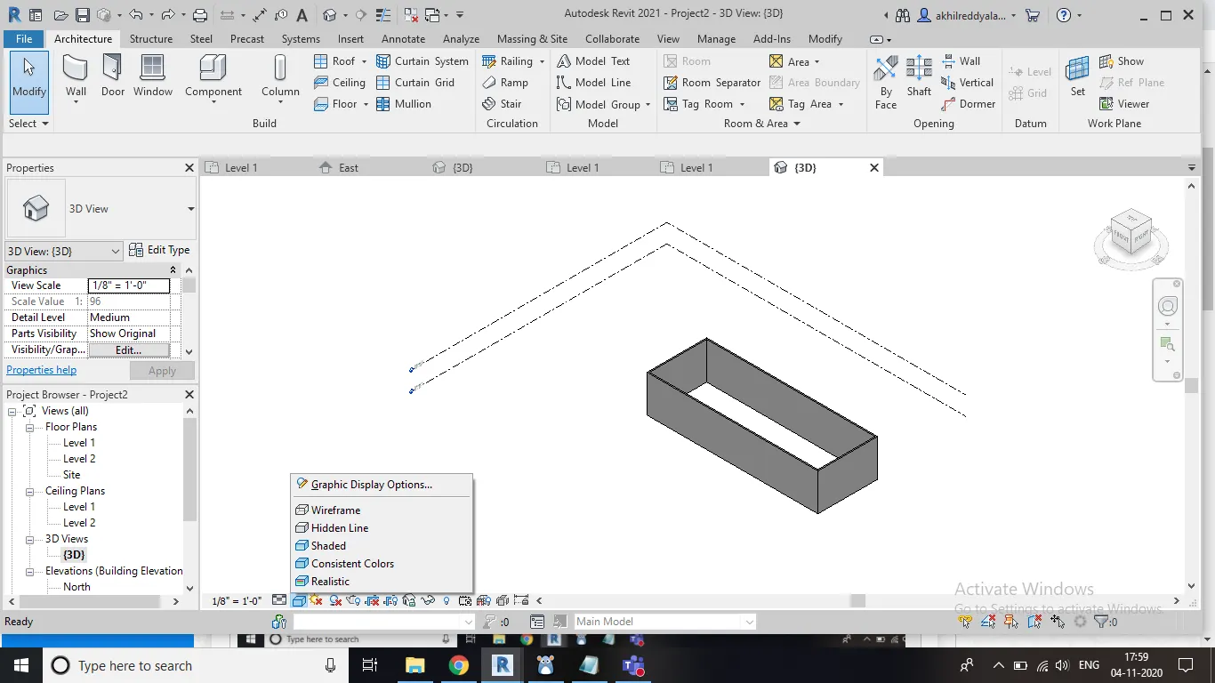
b) Go to graphic display options at the bottom.
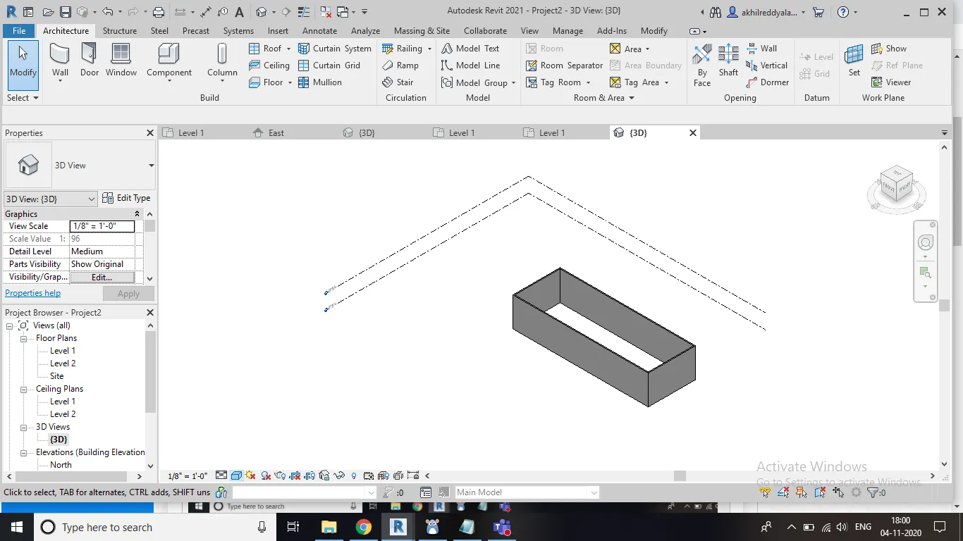
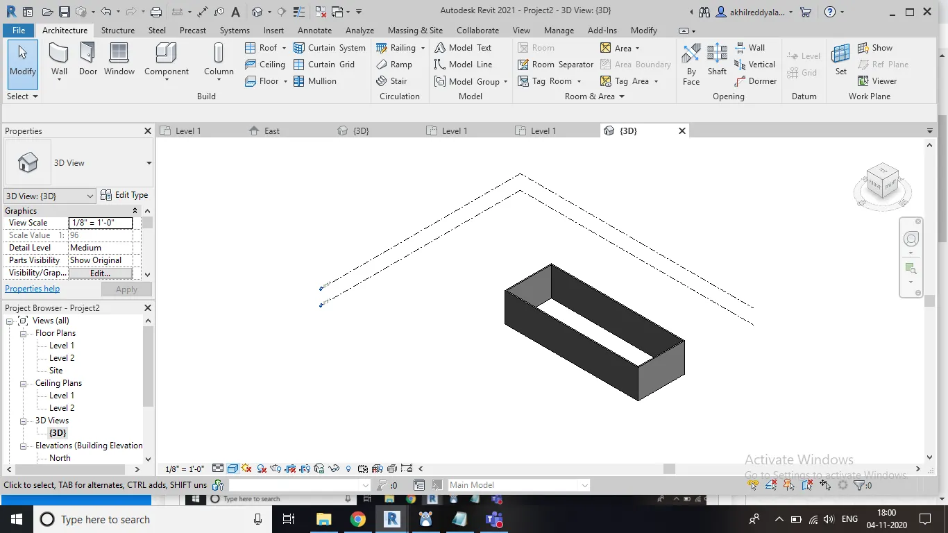
c) In that you can different options like shaded , consistant , realestic etc.
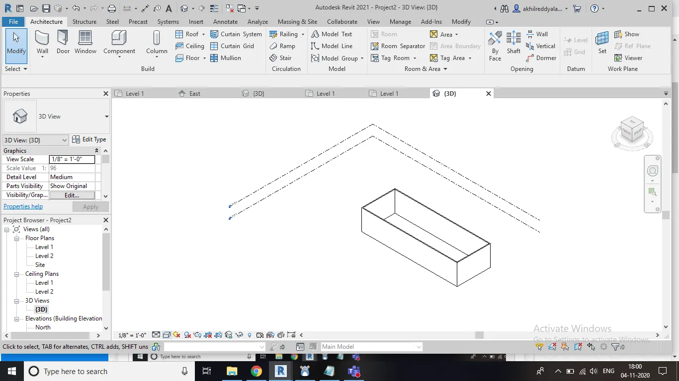
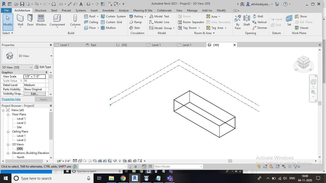
d) You can select what ever you want and change the design of the model.
RESULT : We are able to change the model into different designs successfully.
9th Ans)
AIM : To change the sunlight on and off to view shadings in the layout created
TOOLS / COMMANDS USED :
sun settings
PROCEDURE :
a) Prepare a model.
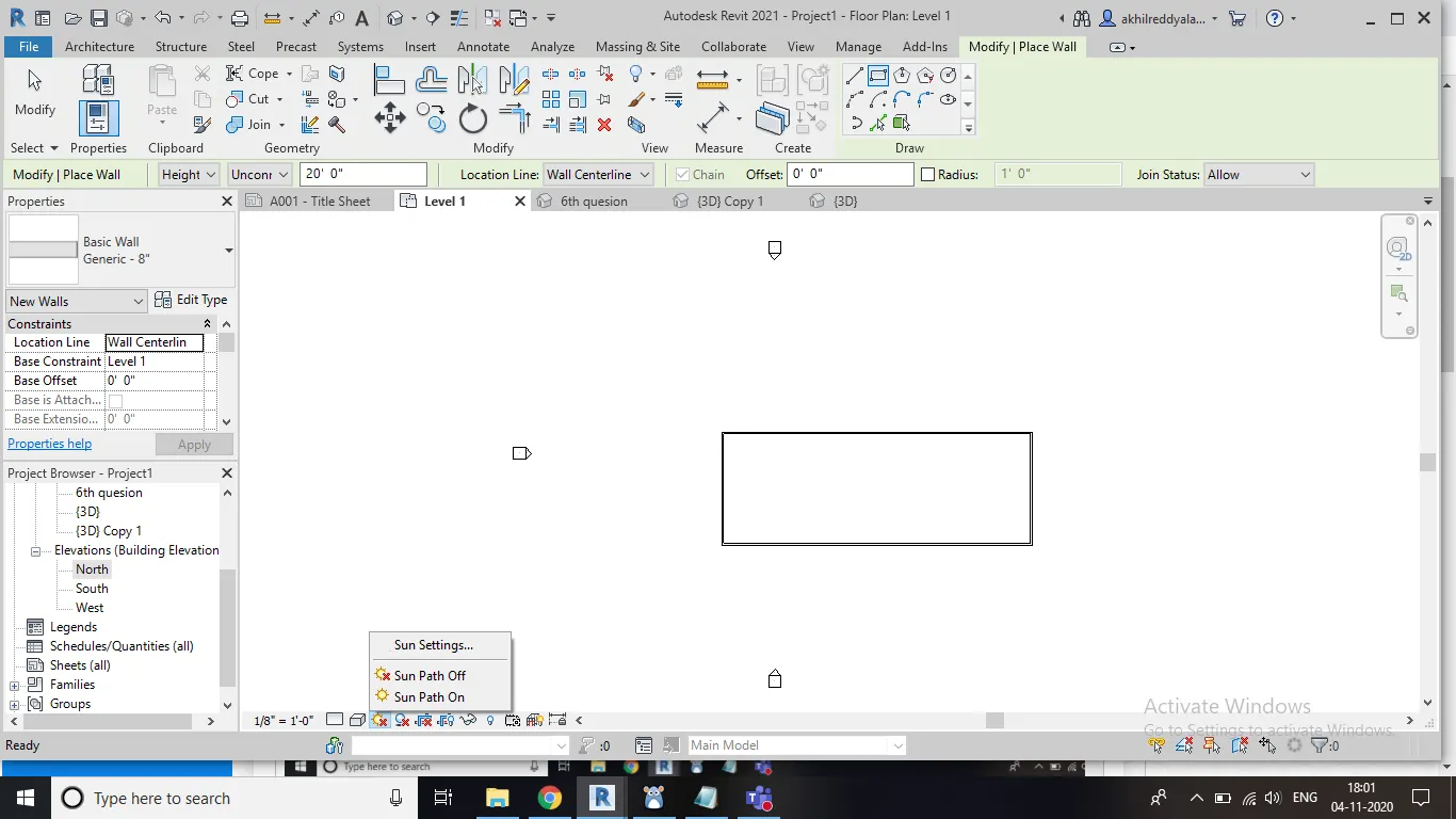
b) In the bottom menu bar you will an option called sun settings.
c) By clicking that you can find two options. They are sun path on and off.
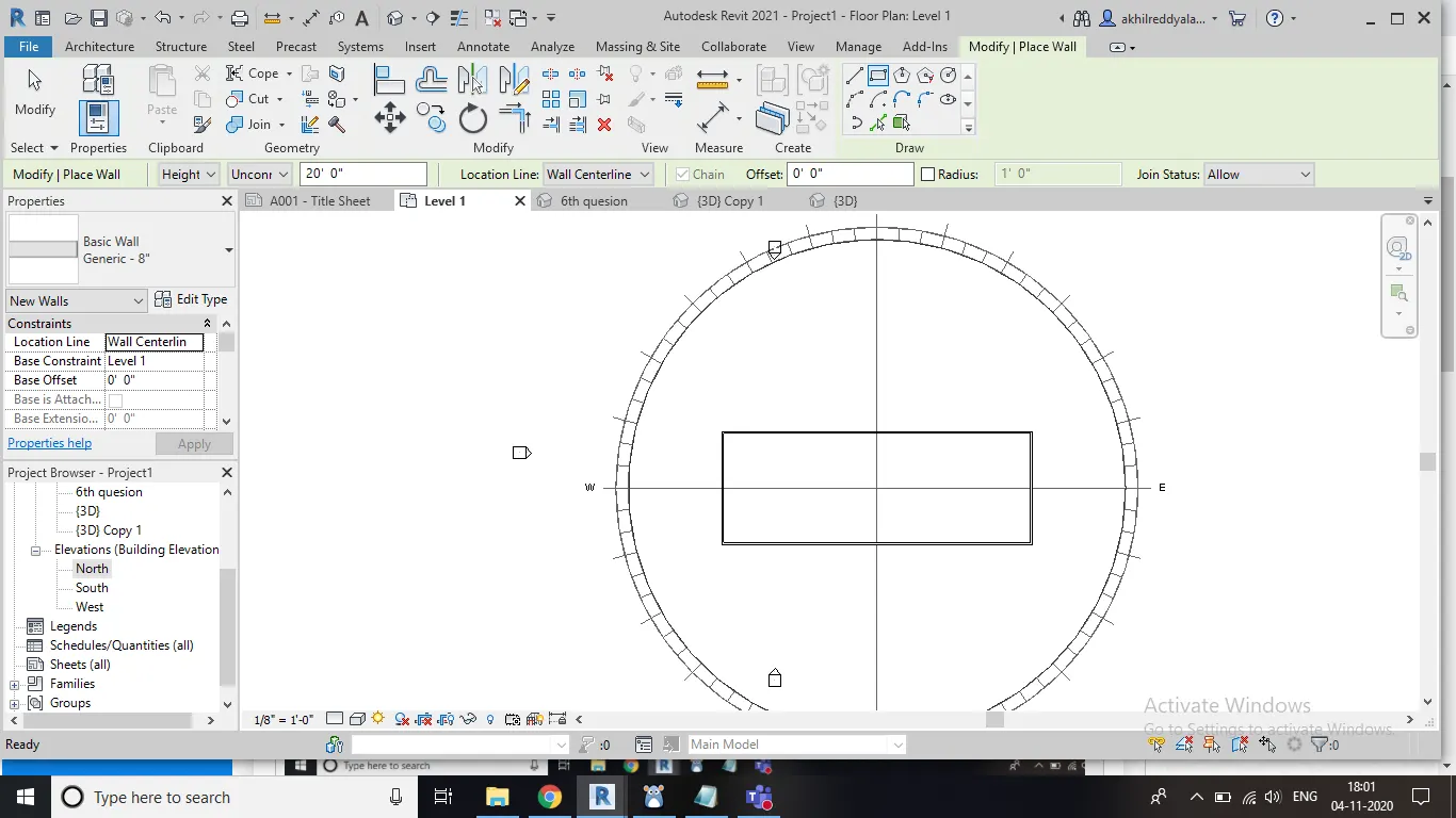
d) You can change the on and off conditions as your wish.
RESULT : We are able to change sunlight on and off shadings in the layout created.
10th Ans)
AIM : By using the manage tool bar to enter project settings, project name and project issue date .
TOOLS/COMMANDS USED :
Manage
Project information
PROCEDURE :
a) Initially create a project.
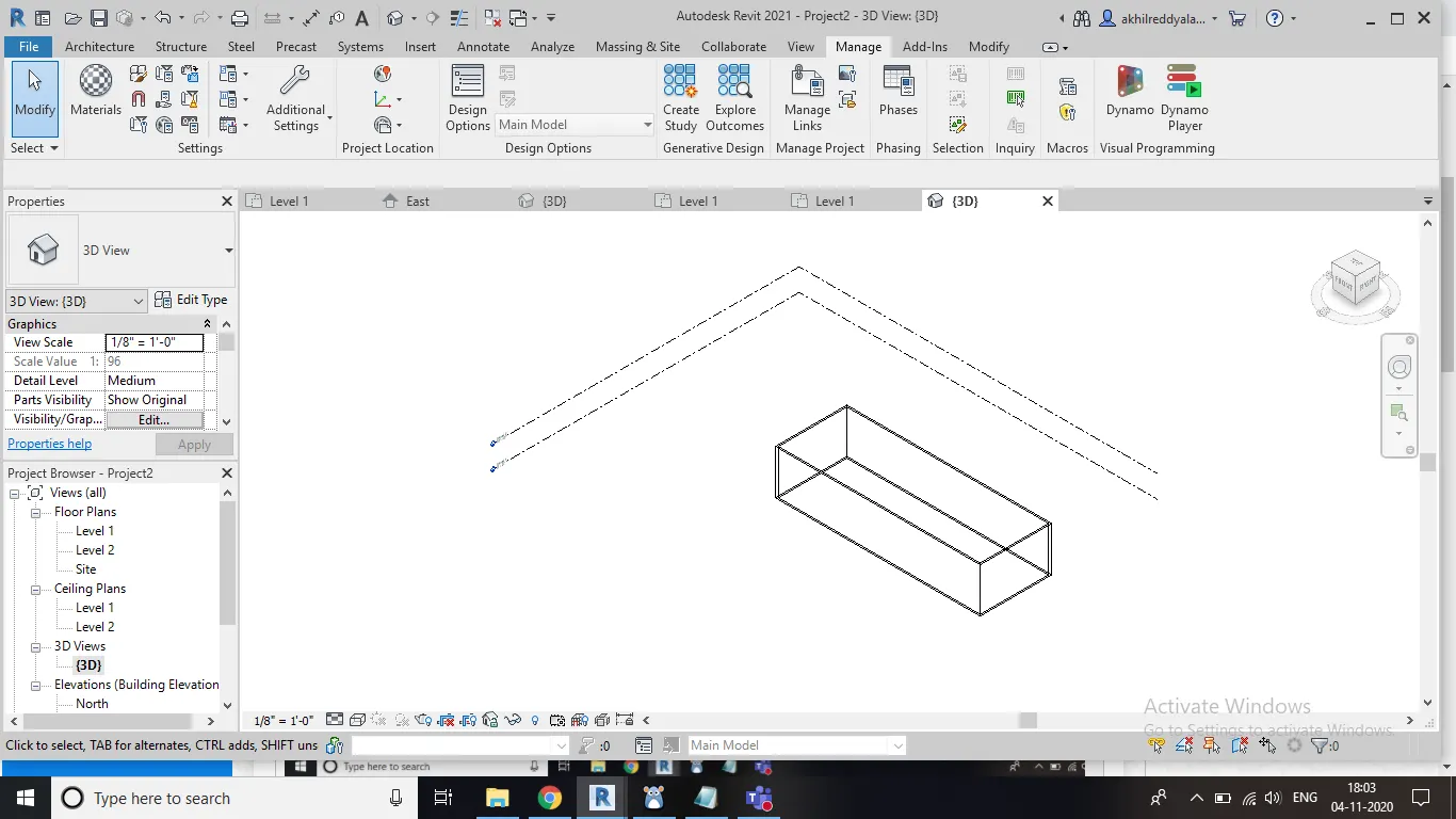
b) You will find a 'manage' option on the top menu bar.
c) By clicking that you can you will get different options on left side.
d) Select project information from that.
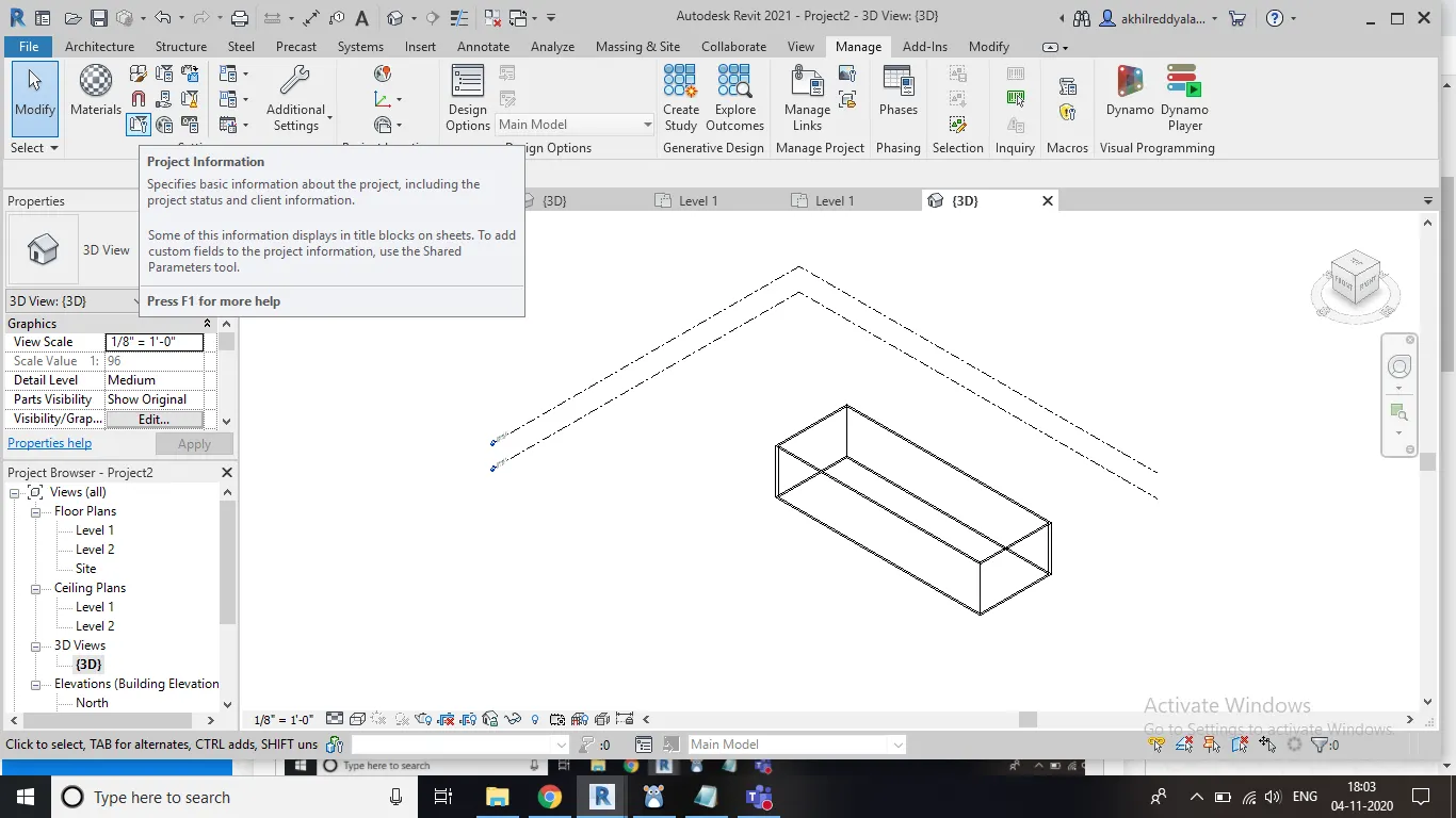
e)Then you will get different parameters.
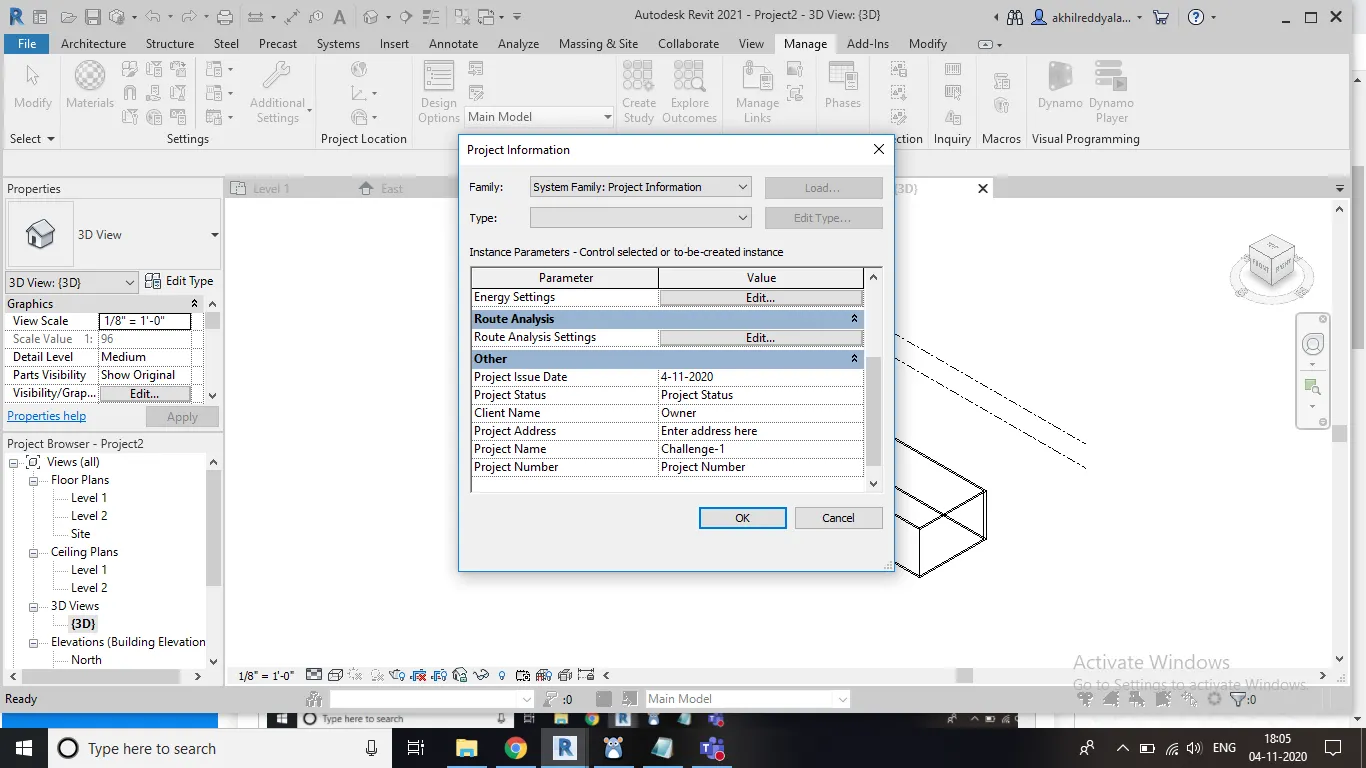
f) Fill those parameters according to your convenience.
RESULT : By using manage tool bar we can enter project details according to our convenience.
11th Ans) Analyze tool bar is a type of tool bar which will combine different loads in the structure , load combination and boundary conditions . It is used to analyze all different types of loads in a structure. Load failure can be identified by using analyze tool bar. It is the main advantage in it.
12th Ans) There are different links that revit supports . They are
Link CAD , link topography ,link revit , link IFC
13th Ans) As we no that revit is a cloud service. Even users from outside the network also can combine on the same project. It is an advantage. Because if different people work on the same project the time will be saved and output will enoromous.