Project 1
Report on project 1:
Objective:
In this project, I have to
- Define the connectors and clips electrically.
- Keep the connectors and mounting clips and other attachments on the engine.
- Finally, rout the wire on the engine part precisely.
Define the connectors:
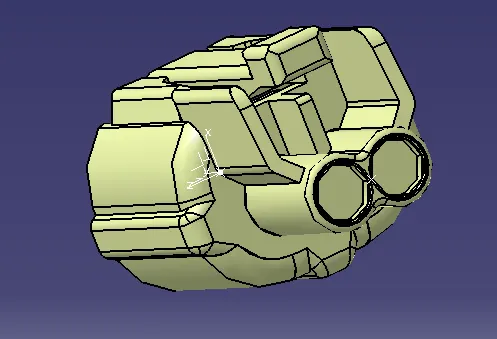
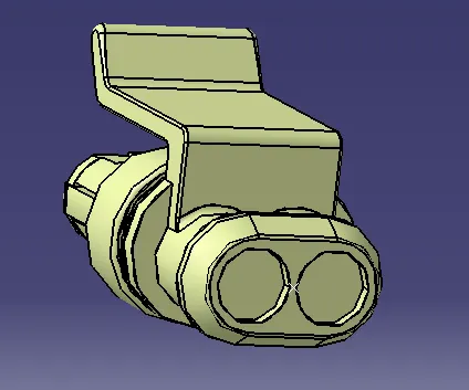
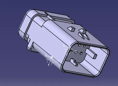
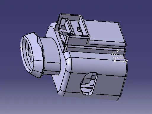
All the connectors are downloaded and saved as a CATPART file. We need four-pole connectors for the cam sensor and injector system. For the neutral sensor and oil sump, we need two pole connectors. And for the coolant temperature sensor, we need three pole connectors.
Now, move to the mechanical part design workbench and add necessary geometries like point, lines and axis system. Now, move to the Electrical Part design workbench and define all the connectors and add their bundle connection point and connector connection point.
Image of the connectors:
Define mounting clips or clamps:
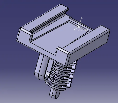
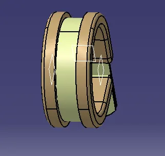
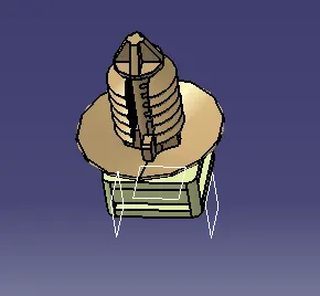
L_clamp, P_clamp and Fur_tree clip is taken as the mounting object for this process. L clamp is taken as the mechanical object in the context assembly and is not a part of the geometrical bundle. But the P clamp and fur tree clip are taken as electrical equipment for this project. So, we need to define these as electrical equipment. For this clip, we need to define the exit plane, entry plane and base plane. And, we need to define this clip in such a way that it should be bidirectional.
Define the channel:
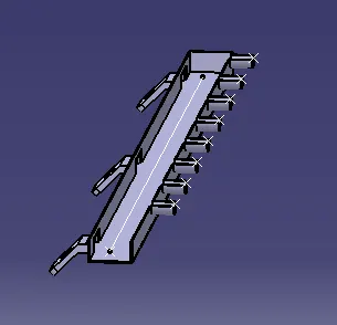
On the engine part, we have to place a total of sixteen connectors and also have to add routing on them. It is difficult to route wires in such a hot and messy place. So, for this type of routing case using a channel is a wise decision. To define the channel electrically we need to define the bundle entry and exit point. This is now ready for use in geometrical bundle assembly.
Positioning the connectors, mounting clips, interconnector and channel:
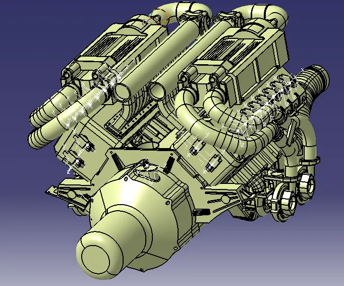
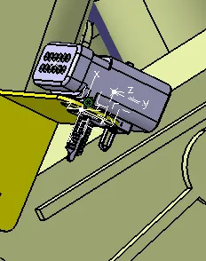
Place the connectors and interconnector at desired location by using manipulation, snaps, smart snap and also using the compass. Then, the mounting clips are added to reduce the routing complexity. Channels are also added regarding safety and also for better routing.
Image of the arrangement:
Routing the wires:
After all the arrangements of routing equipment, it is ready for routing. I have started routing from the left side of the engine where the interconnector is placed. And using branch definition and adding branch point commands to create routing wires to connect all the connectors and clips.
For routing inside the channel, we need to use external reference command to rout the bundles.
Image of the routed engine:
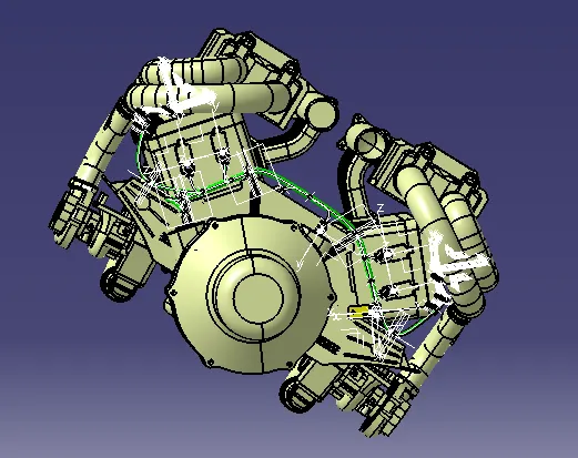
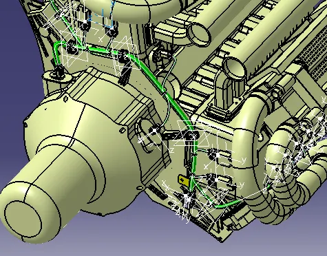
Image of the routed channel:
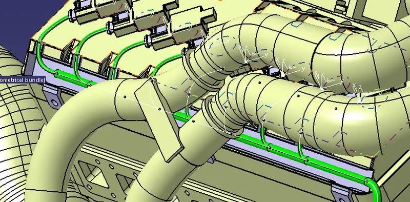
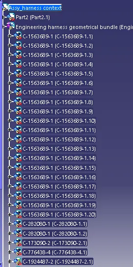
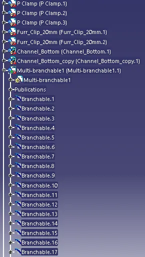
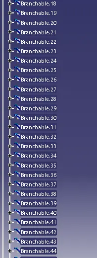
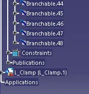
Image of the feature tree of the final harness assembly:
Storing components in the catalogue:
Now, create one catalogue and store all the connectors and clips in it.
Conclusion:
Routing is done on the engine part is done using different workbenches of CATIA V5. Useful assumptions and routing decisions are made to do this project.