REVIT_3D rendering of a house plan_project1
1:Aim:Based on the project saved from Week 3, proceed from First Floor Level .Model a Ceiling from architecture tab above the walls at first floor level
procedure:
a:open the week3 project from files menu load it.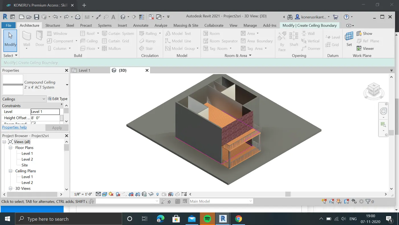
b:now open the architecture tool and select the celing option.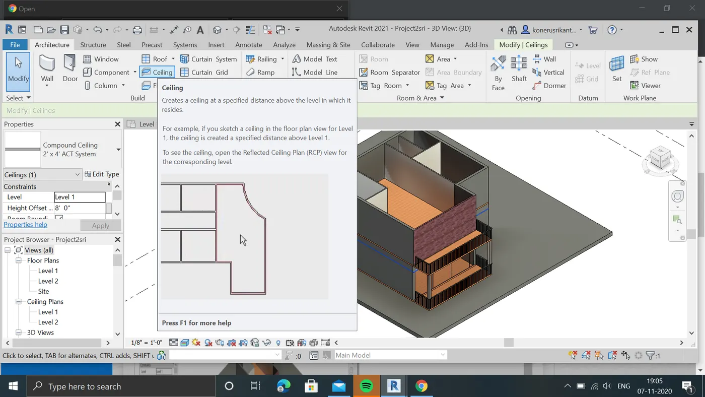
c:we can see that celing tab will open rightcorner on toolbar now select the sketchtool.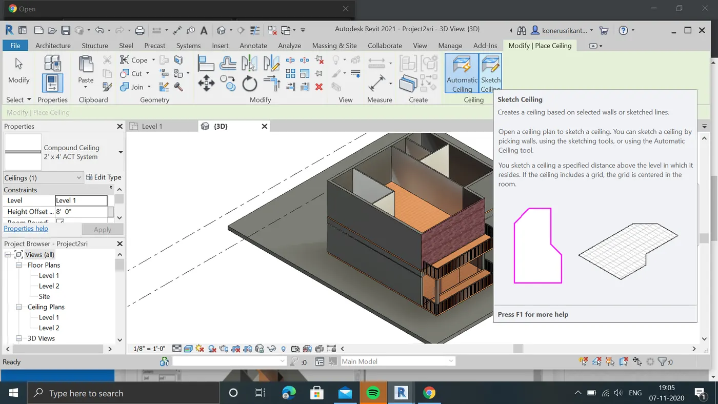
d:by selecting it by using picklines option select exterior walls of firstfloor to add celing to it.
e:after selecting exterior walls and enter ok we can see that celing is added to floor.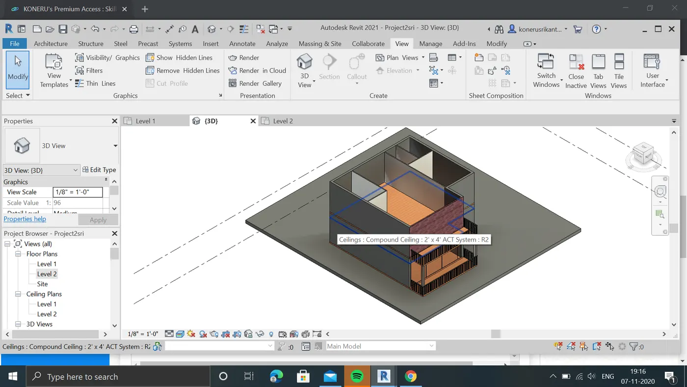
result:celing is added to the 1st floor sucessfully.
2.Aim:to Model a roof above the ceiling by selecting the footprints of ceiling. Using the adjustment tool bars appearing on screen adjust the roof slope to 10 degrees
procedure:
a:now remove the 1stfloor from the project file.to add floor to ground level by celing footprints.
b:after removing the firstfloor select the roof opton in architecture tool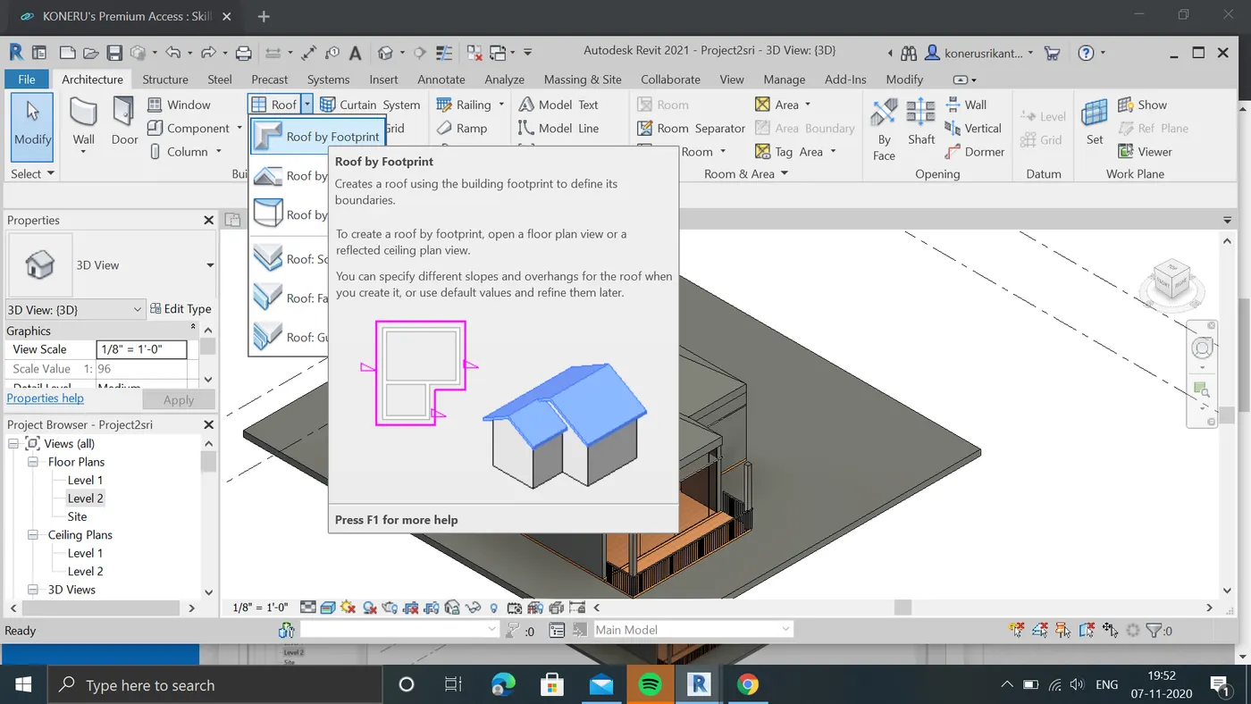
c:by selcting the roof by footprint now select the pick lines to select the celing
d:now select the celing it turns into pink colour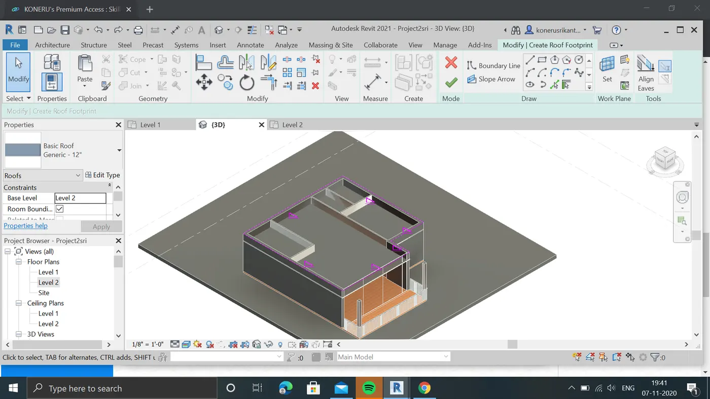
e:by selecting ok we can see that roof is added project file.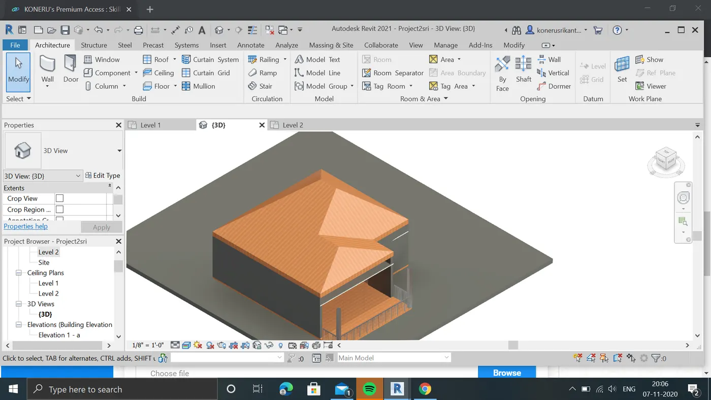
f:now slope is adjusted to 10degrees in dimensions from properties converted to required units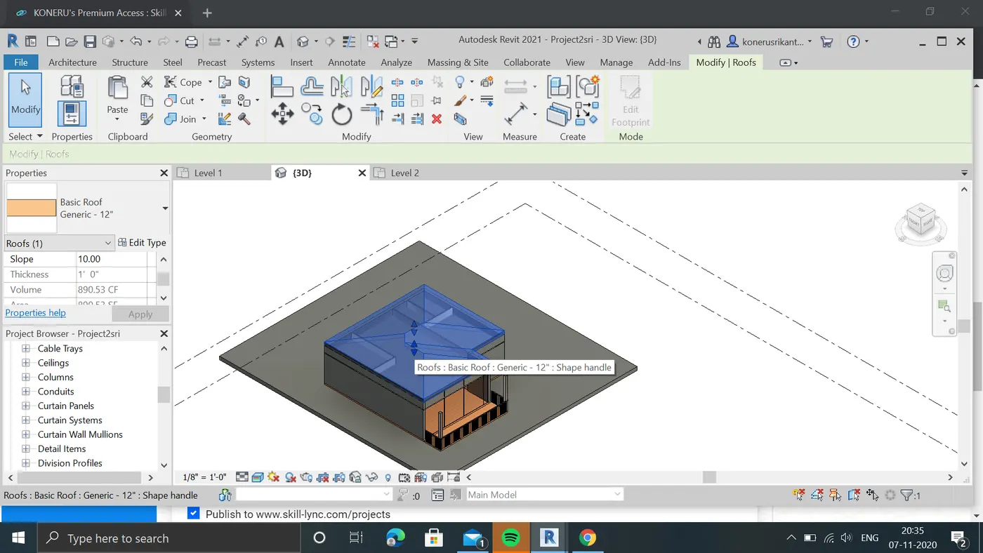
g:these is the final view of layout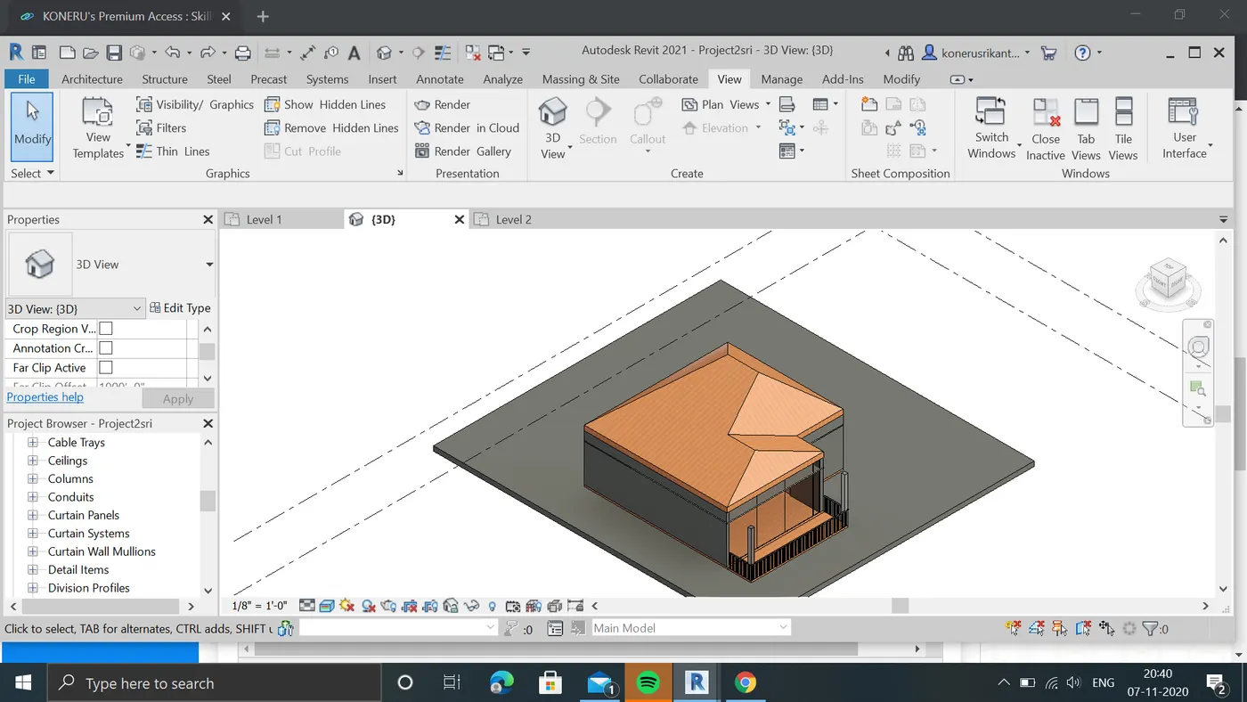
result: roof is added to layout by delecting footprints by celings and adjusted to 10degrees.
3:Aim: Using the file saved from week 2 to 4, create plan views for ground floor level and first floor level including all the walls , floors and components. Separate them to
architecture and structural plans
a. Architecture plan must have walls , floors and all the components placed within the building
b. Structure plan must have details of only walls, floors and columns
Procedure:
a:load the privious project file .
b.now select the architectural plan view in view toolbar.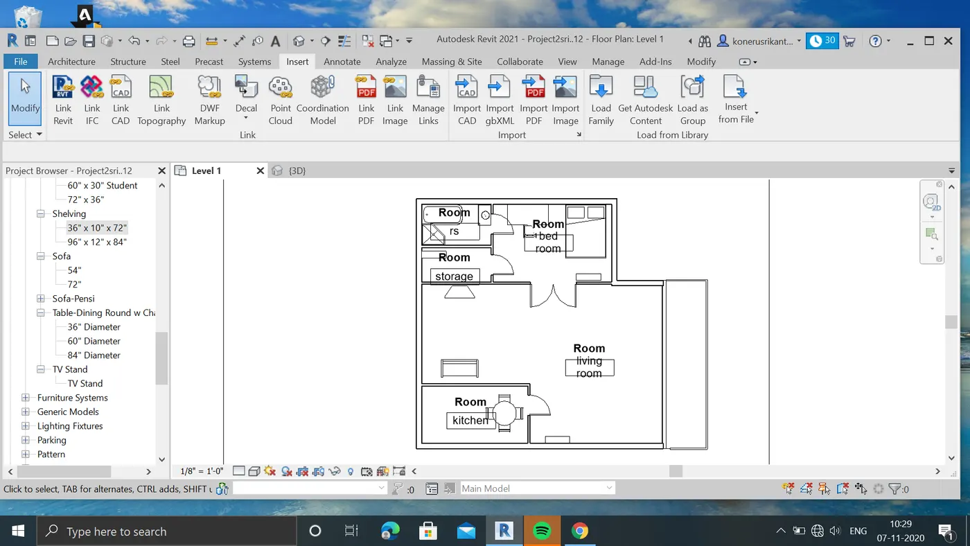
c:architectural plan contains all components that added to it and walls.
caseb:
a: now select the sturctural view from view toolbar in plan view.
b: we can see that view is created with walls and coloums
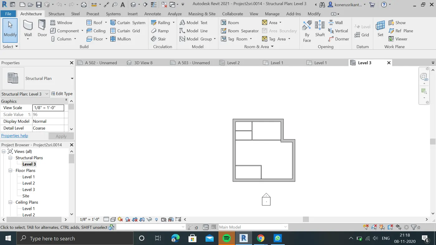
result: architectural plan and sturctural plan is created sucessfully.
4.Aim: Using annotate tool bar add dimensions to all the walls and floors with reference to the longitudinal and transverse grids created in the project file.
a. The architecture plan dimensions include details on where the components are placed within the buildings with relation to grids. Overall dimensions are sufficient for architecture plans
b. The Structure plan dimensions must include details on position of all the walls and interior walls with reference to grids. Locate all the framing components of the building with reference to a fixed point using Structural plans
procedure:
a:Open the previous project file,
b:now select the grid option toolbar present archtecture tool in menubar.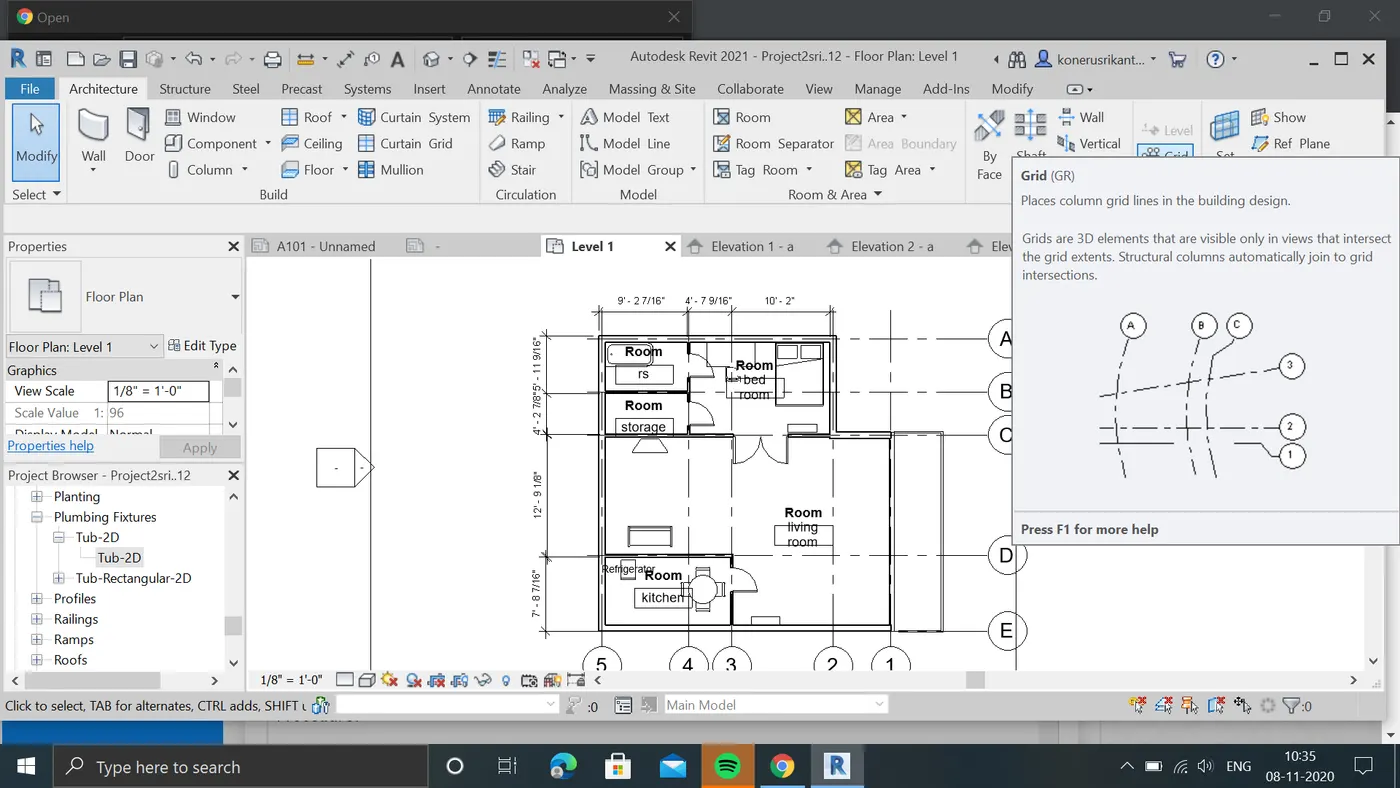
c:by selecting we add grid lines to the projectfile.
D;after adding gridlines by using annote tool add linear dimensions to it.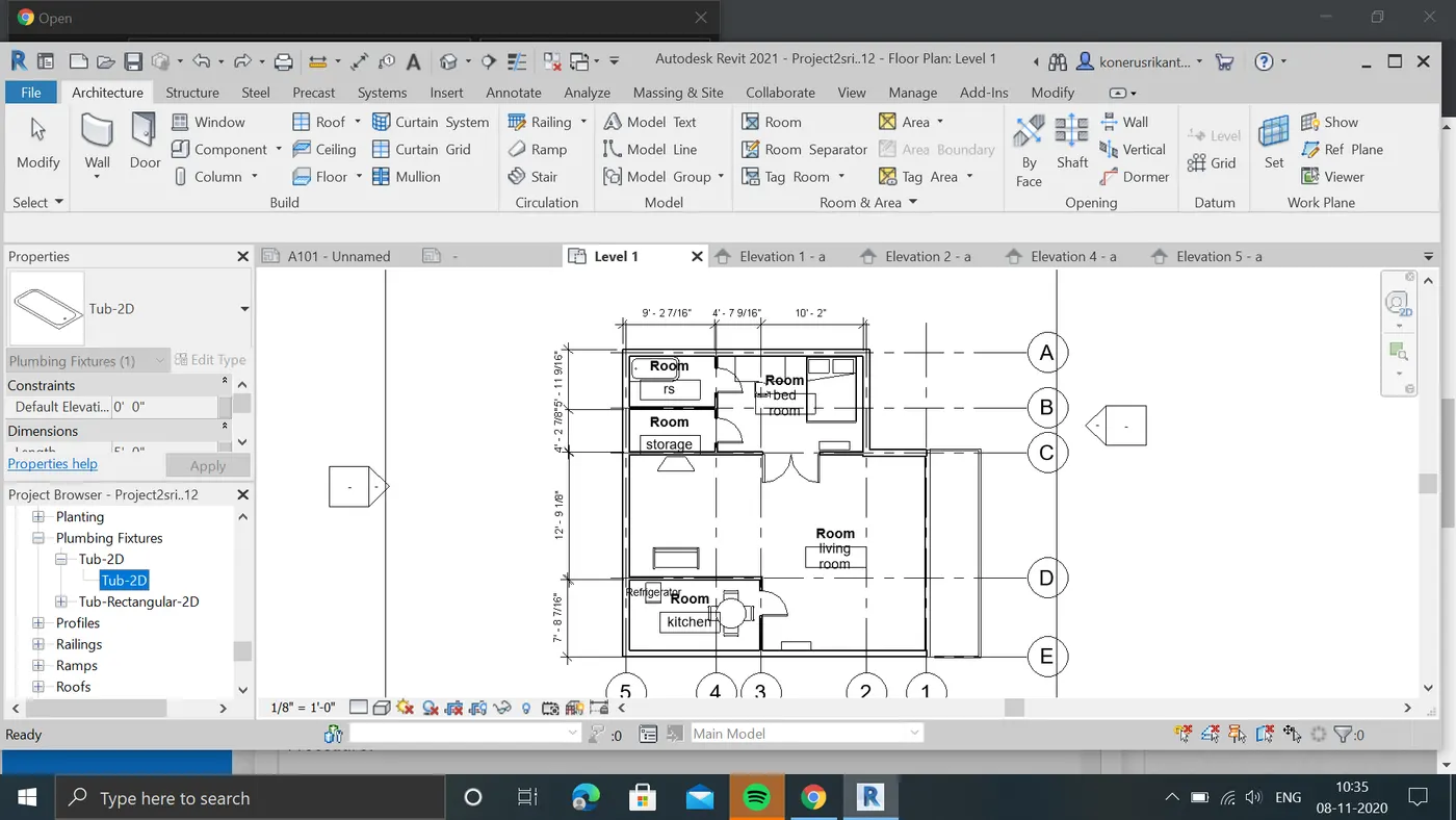
case .a: now add required elements to projectfile and components
b; AFTER adding the elements to project from families now select the component it shows the area coverd by component.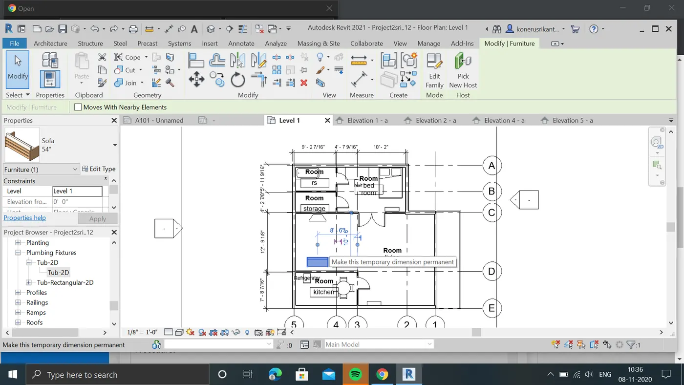
result: created grids and dimensions are added to it with architectural components with realted to grids.
a:open the level1 in 2d view to add grid lines for the projects
5:Aim:) T0 Create a sheet template from the view tab and adjust the parameters on the sheet to add appropriate views
Procedure:
a;now open the view tool in toolbar .
b:now select the sheets option in view tool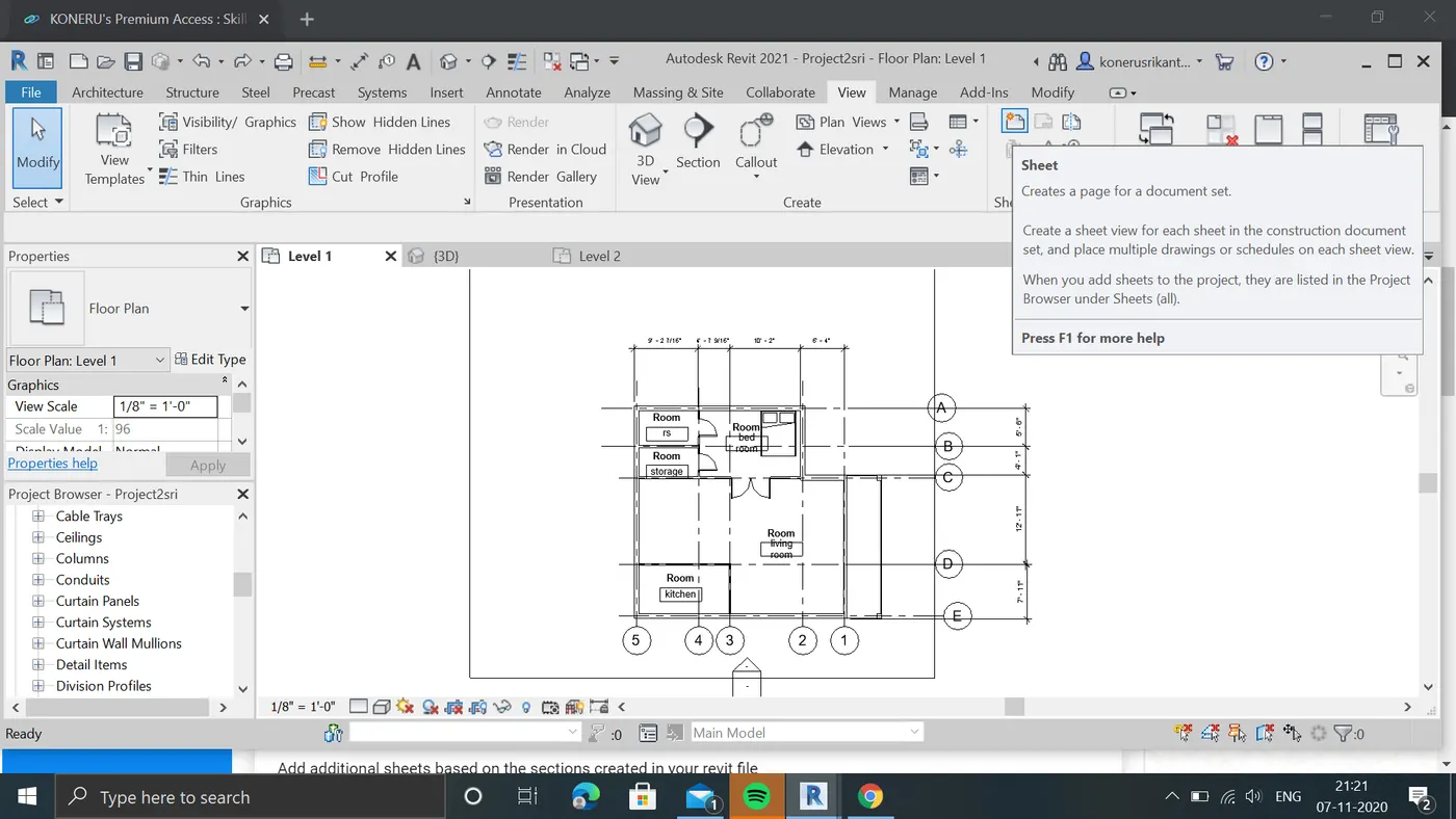
c:by selecting it a new window will open by selecting it a new sheet is created.
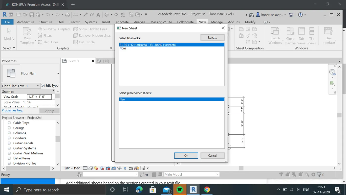
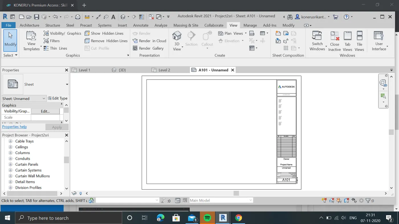
d:we can adust the parameters of sheet by selecting the details in sheet and entering our required parameters and selecting into load project we can see that our parameter adjusted.
f:we can also adjust sheet name,numbe,issuedate,owner etc by selecting sheet and making changes in properties by identitydata tool.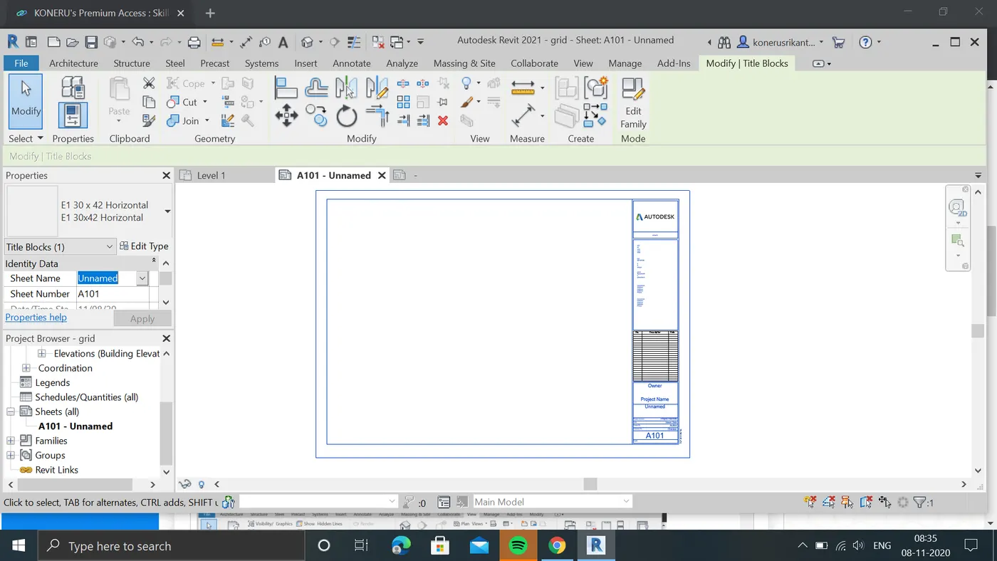
result:created sheets and adjusted the sheetparameters in project file
6:Aim:Using the elevation tab create the elevation views, looking at your building from East, North, South and West
procedure:now create the 4elivation views to projectfile by selecting evlivation in view tool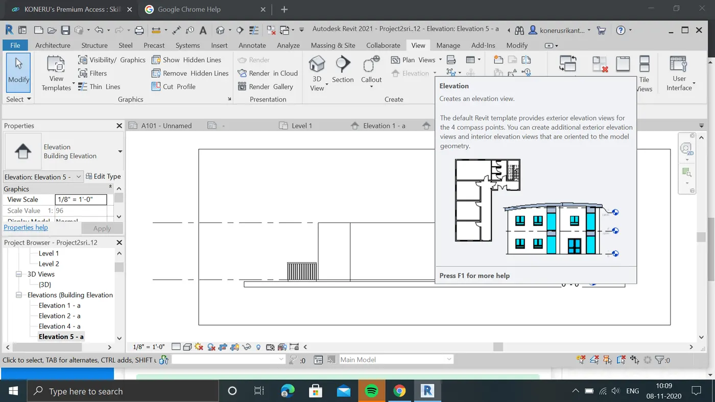
b:4 elivation views are created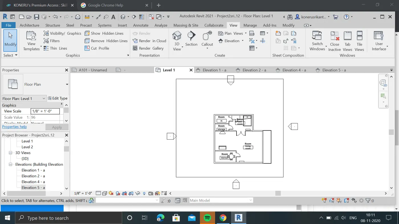
c:we can elivationtool in project browser by selecting it we can see that 4views of project,
d:elivation view of north,south,east,west as followa
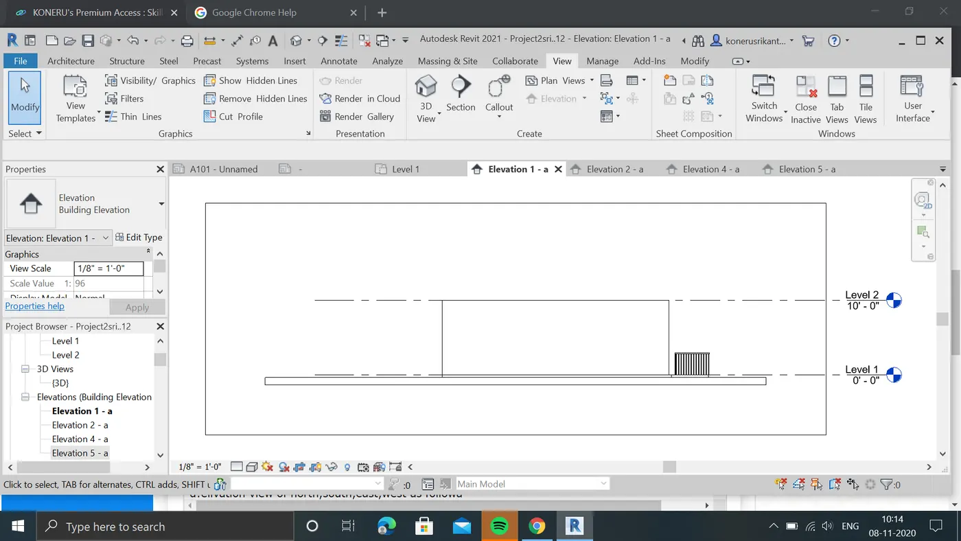
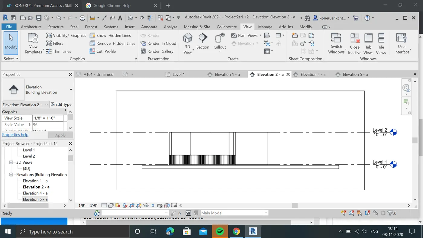
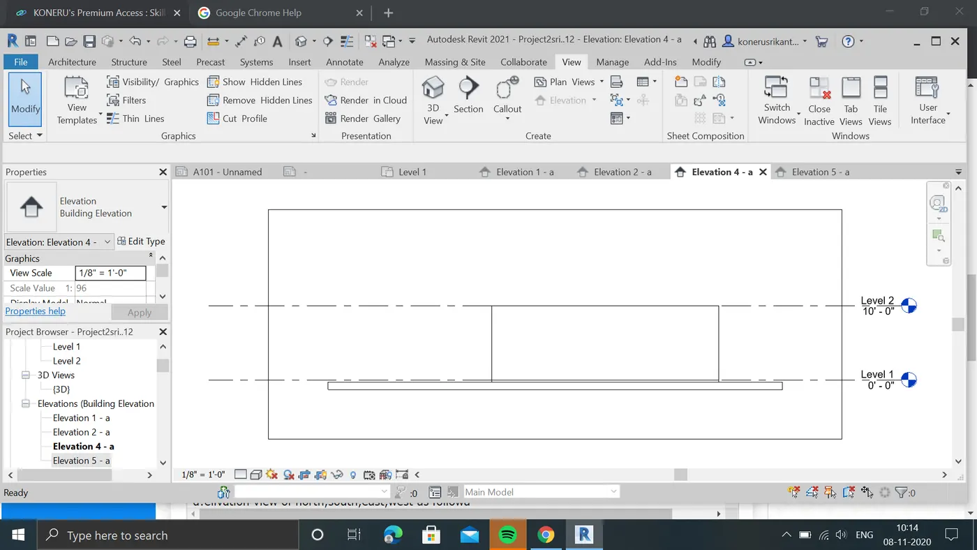
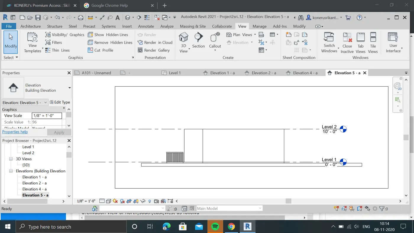
result:elivation views of project file is created ie.north,south,west,est.
7. AIM:To Produce section cut through each room either cutting across longitudinally or in a transverse direction
Procedure:
a:open the level1 of project file.
b:now open the section in view tool to create section in project.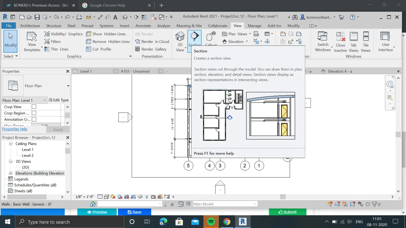
c:now select it and select the section portion in project file.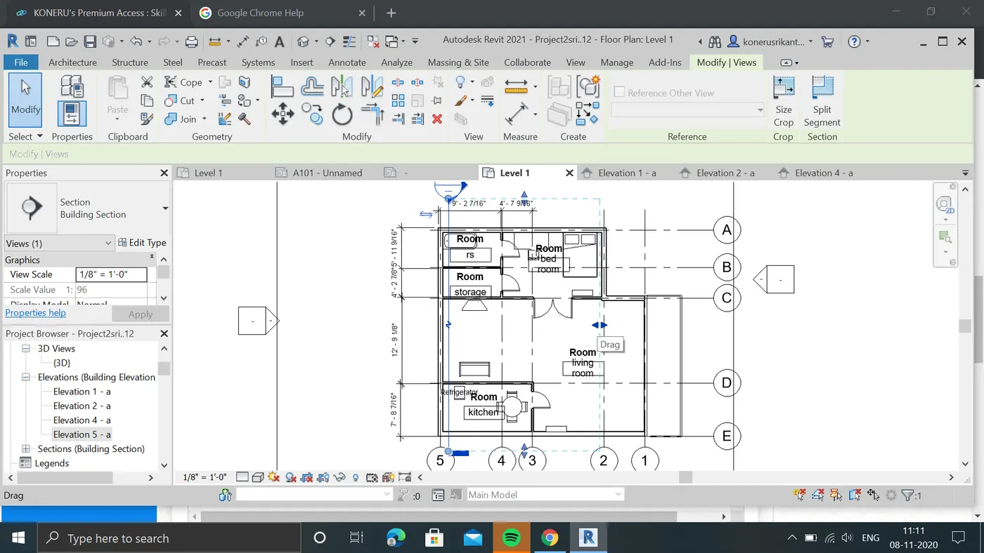
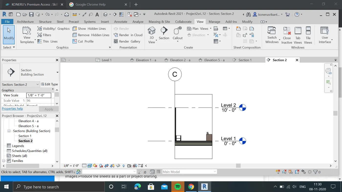
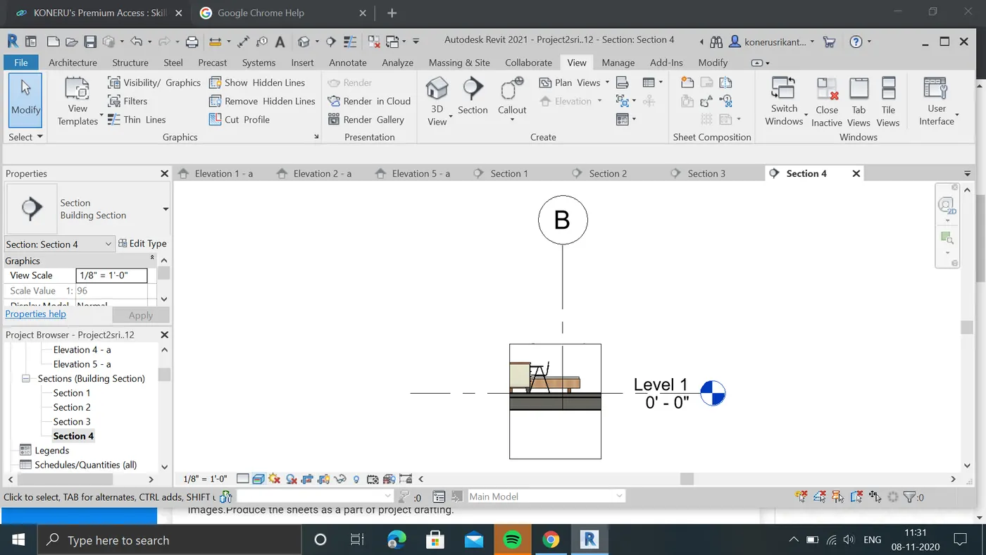
d:we can see that section view is created in properties open the section .
e:section view is opened in new window.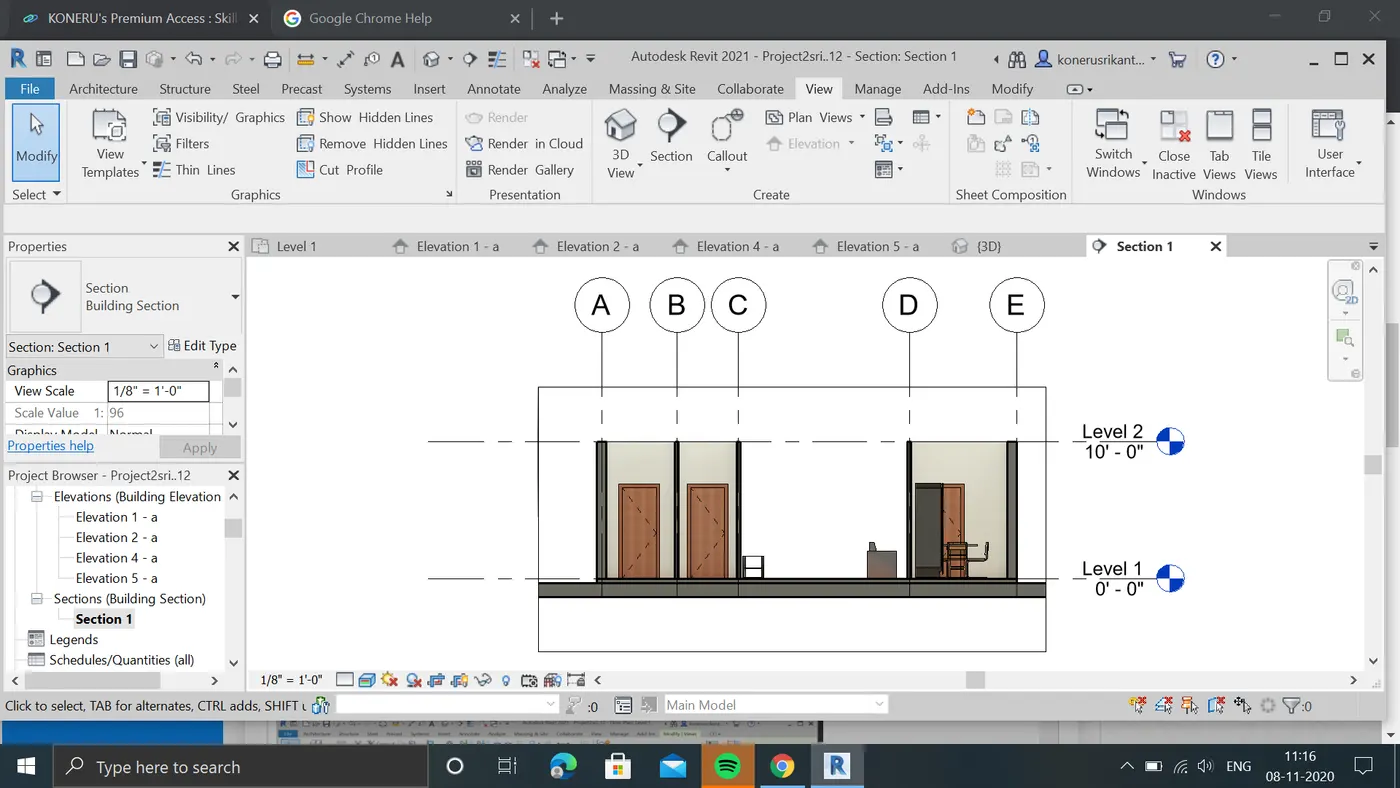
f:sections of each rooms are attached down
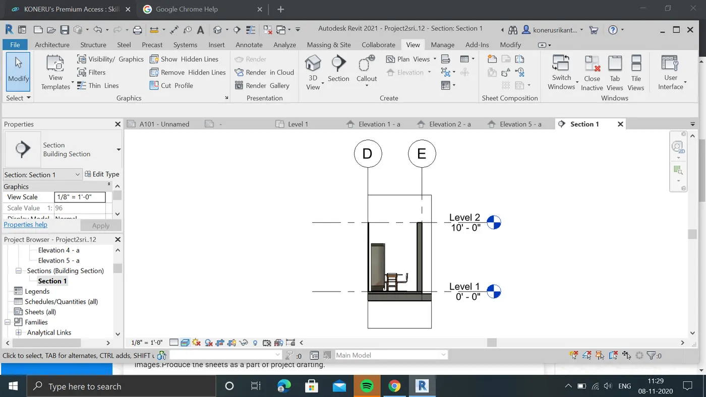
result:sections are created through each room sucessfully.
8:aim:to Classify the views , Plan Views, Section Views and Elevation views to either Design or Documentation category using Properties browser.
procedure:
a:select the sheets from view tab.
b:in new window we can see that sheet is created.
c:now selecting required views from project browser drag it in to sheets.
d:this the floor view sheet i created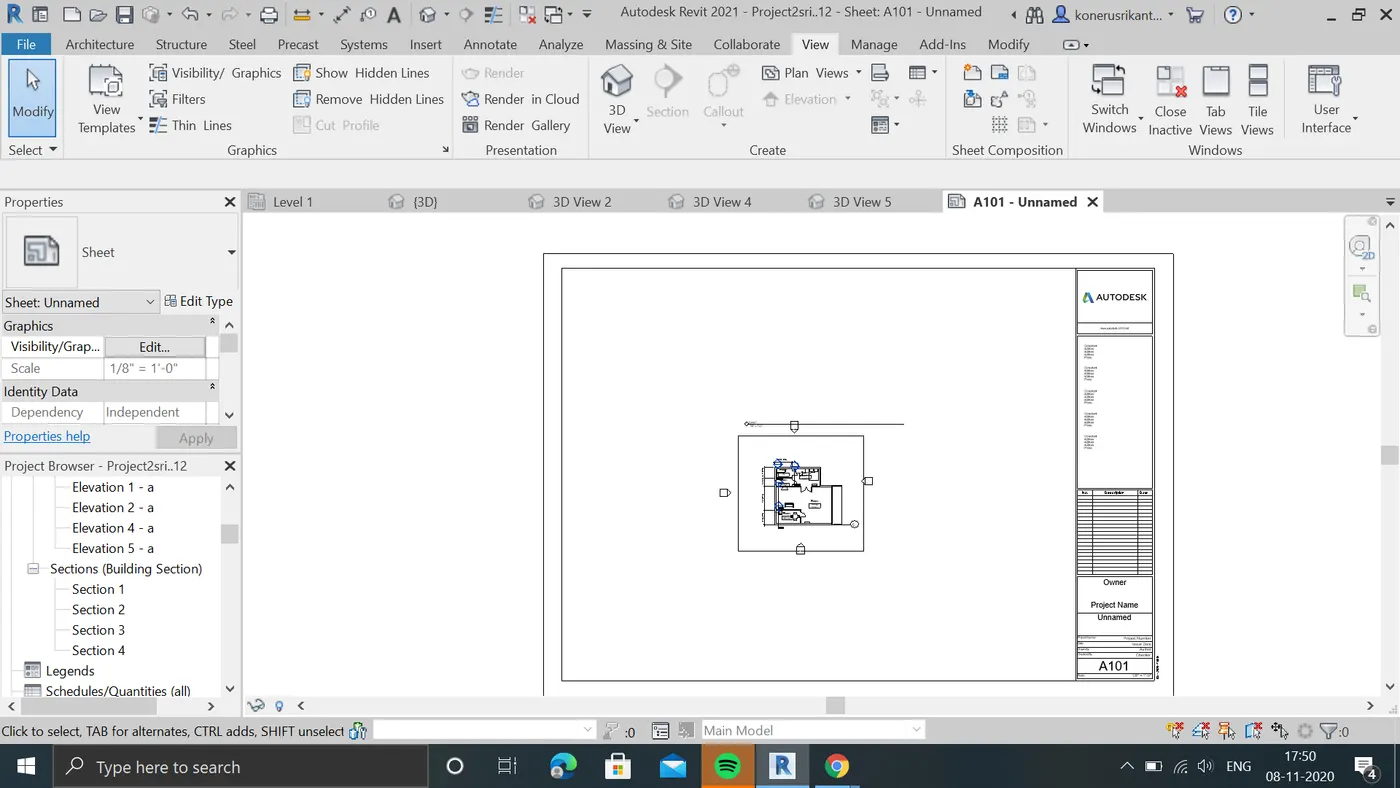
e:these is the elivation views sheet.
f:these is the section views of sheet i created.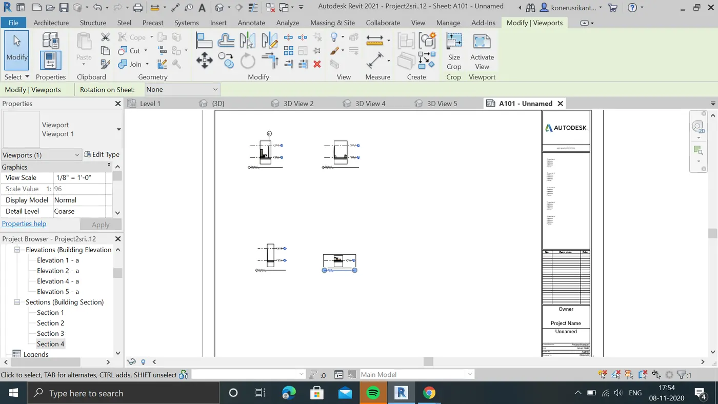
result : plan,section,elivation views are classifed with using projectbrowser sucessfully
9:aim: to create multiple sheet with respective elements.
procedure:
A:open view tool and select the sheets.
a. A 101 – Ground Floor Architecture Plan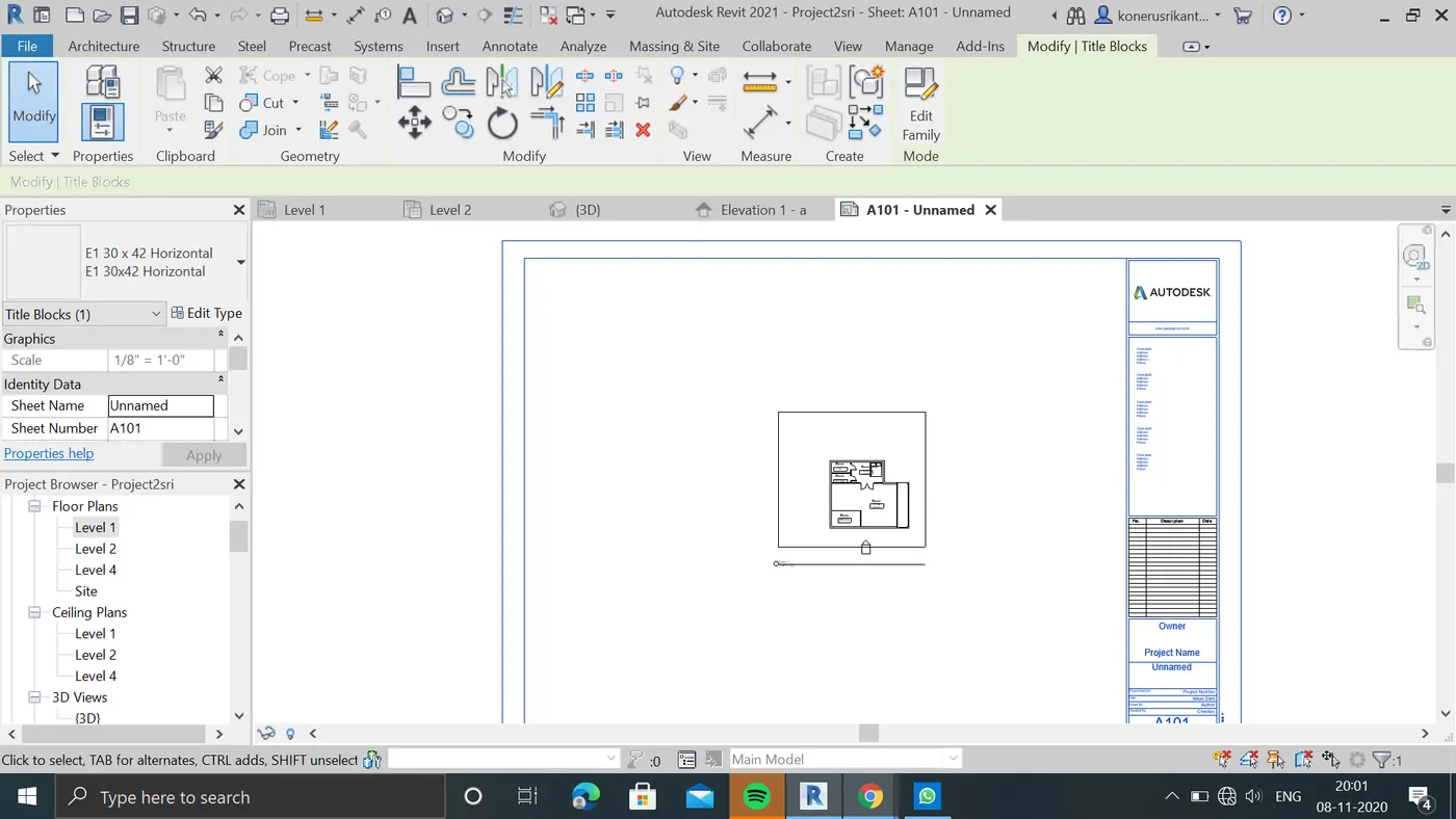
b. A 102- First Floor Architecture Plan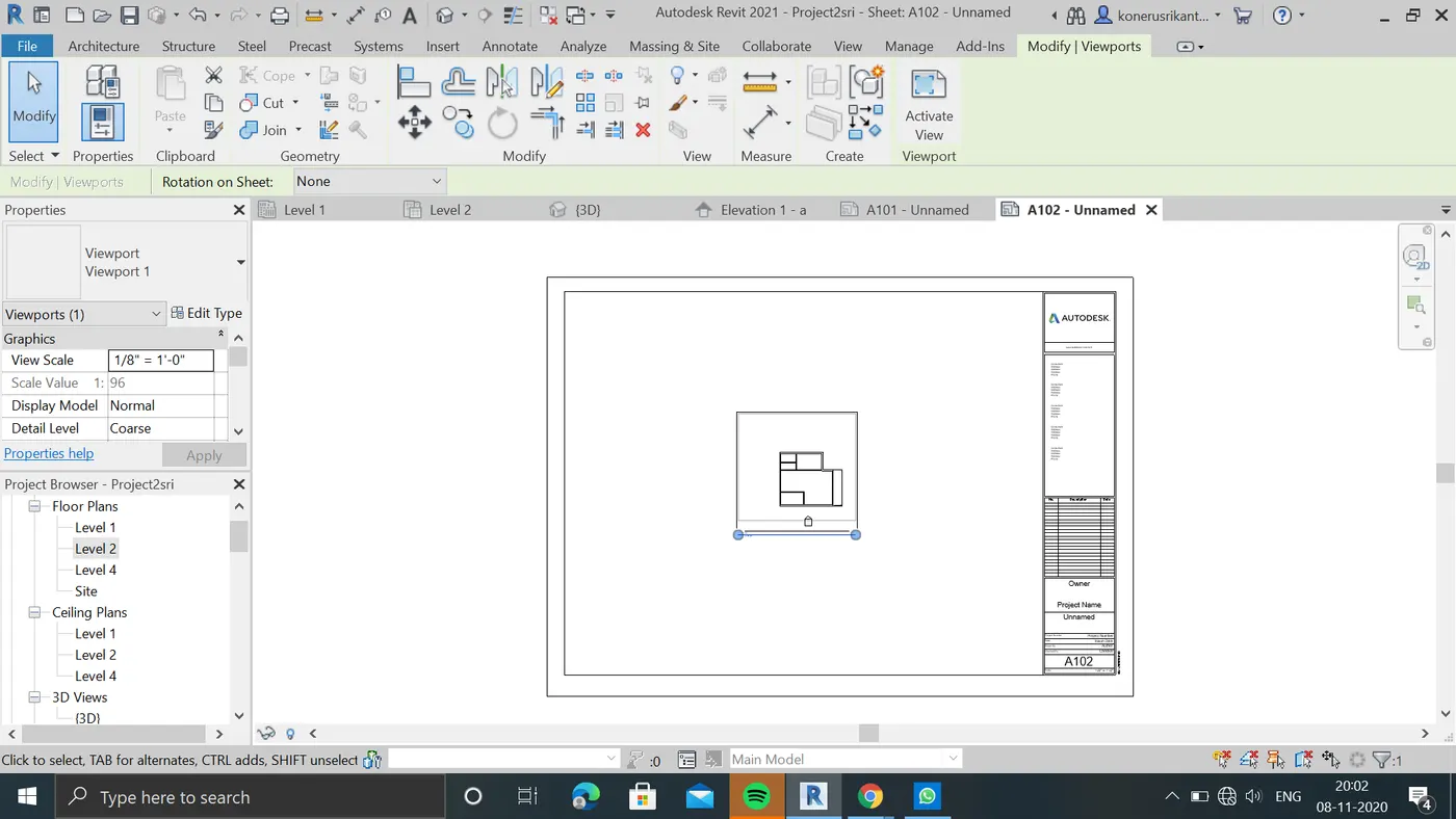
c. A 103- Roof Plan
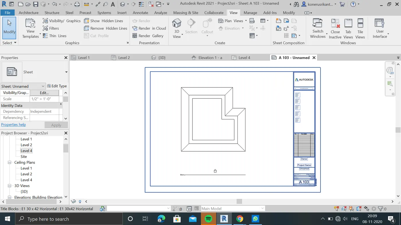
d. S 101- Ground Floor Structural Plan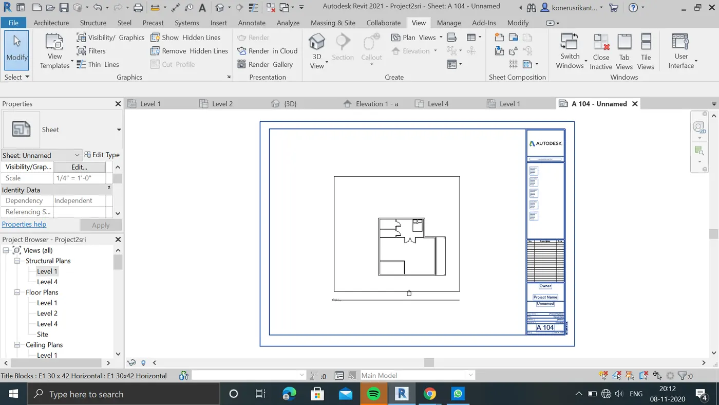
e. S 102 – First Floor Structural Plan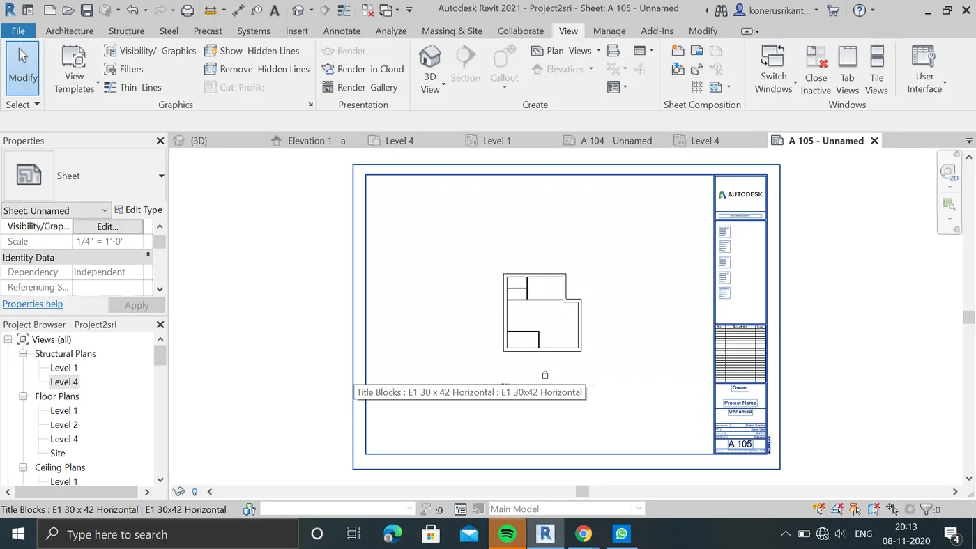
f. S 103- Roof Framing Plan
g. A-201 – North South Elevations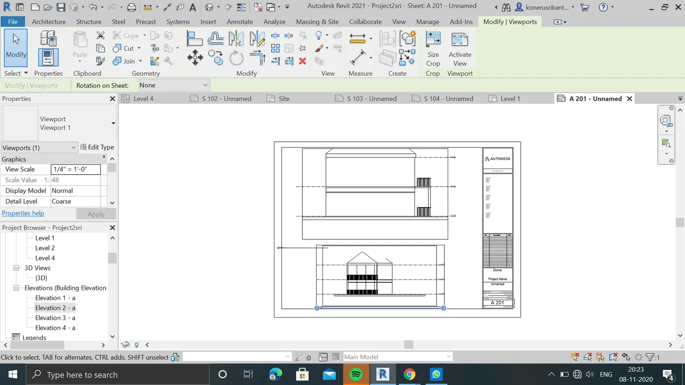
h. A-202- East West Elevation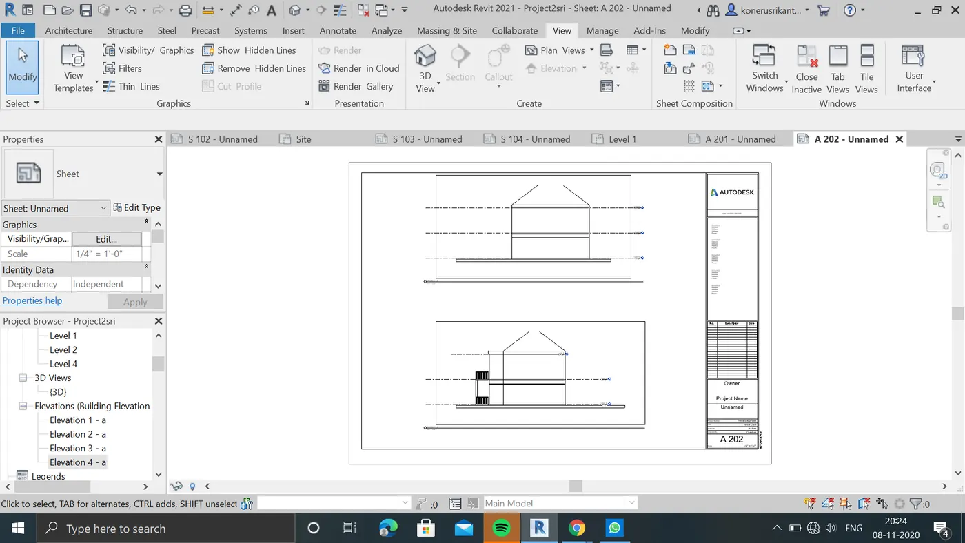
result;multiple sheets are created sucessfully.
10:aim: to Create a camera specific view or a 3D view in each room ( living, dining, bed room ) . Based on the views create new shet of sheets starting A-501 (you can add as many sheets after , 502, 503.. n)to place the 3D view images.Produce the sheets as a part of project drafting.
procedure:
A: now select the camera option in view present 3d tab.
b:now select the project in 3d view to add camera views
c: now load the sheets as A-501,.....
D:NOW drag the 3d views in to the sheets.
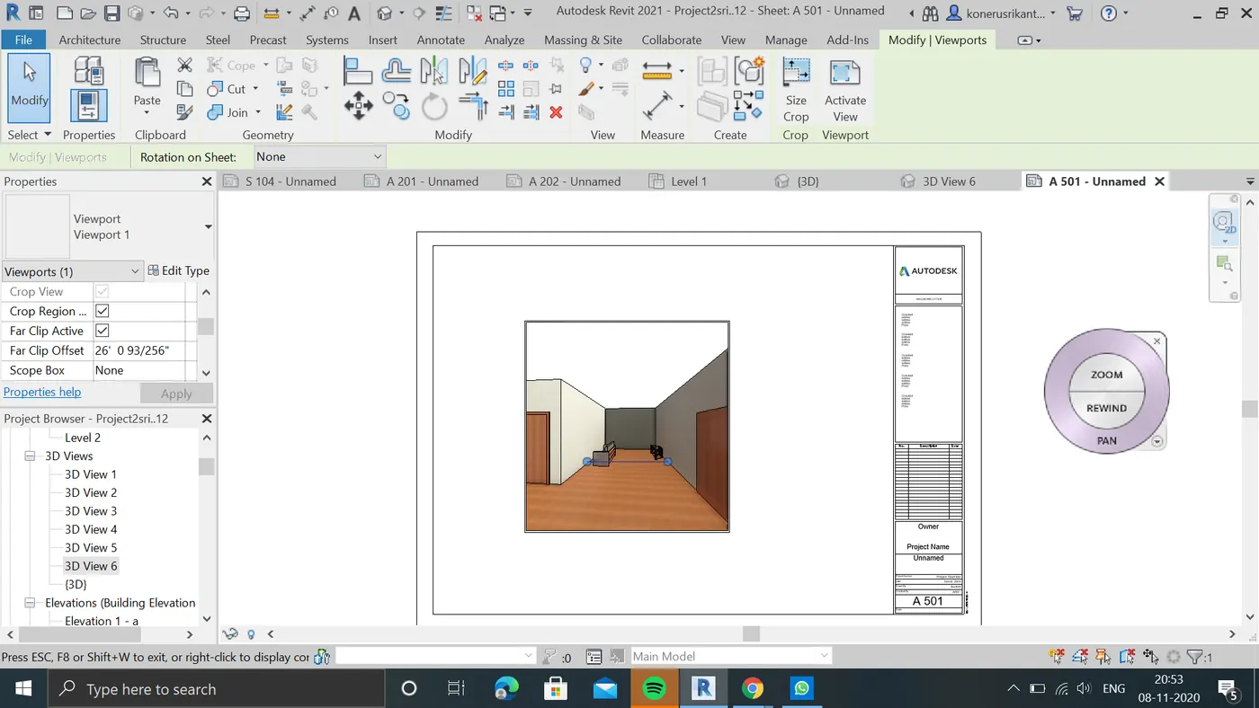
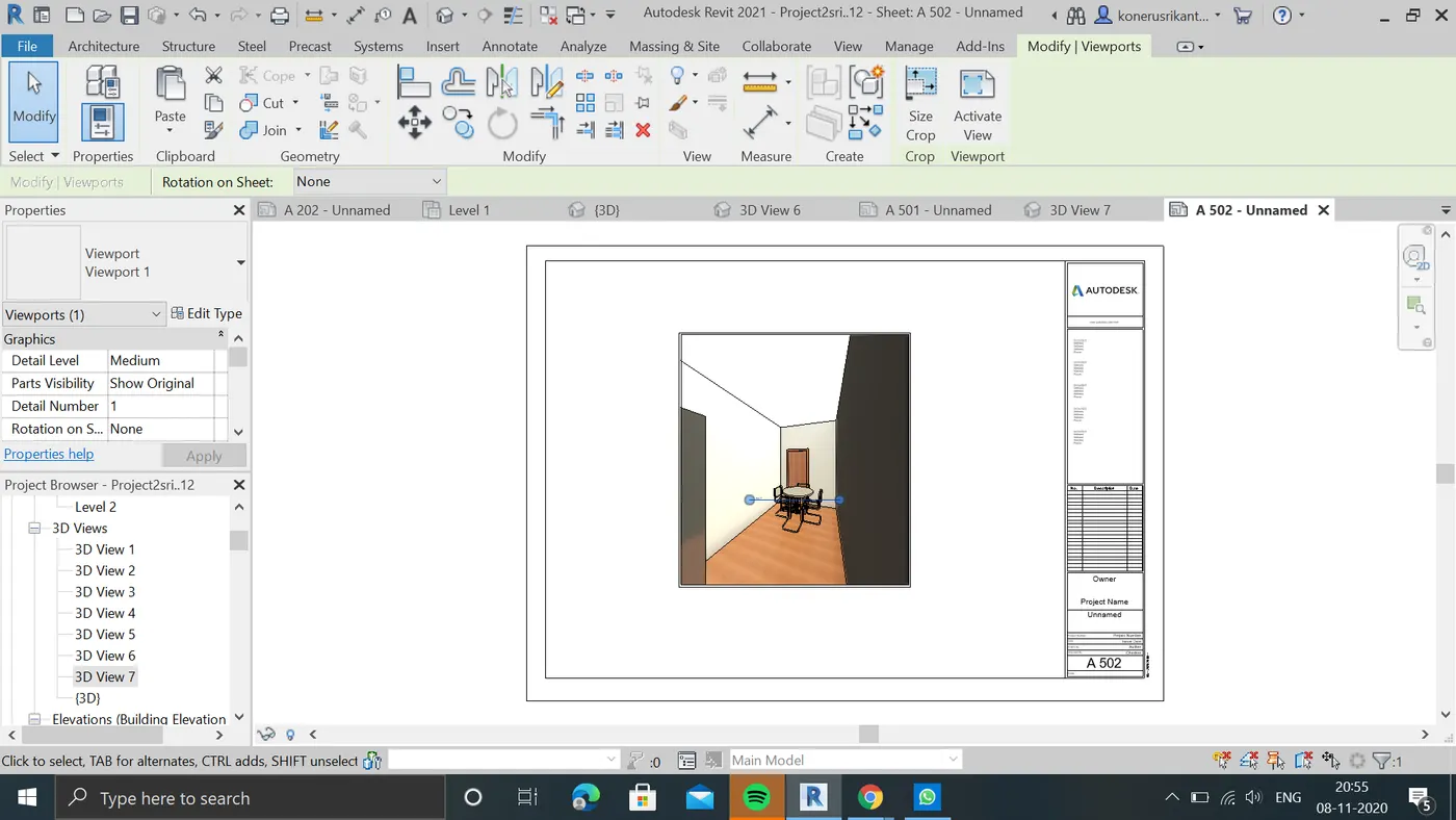
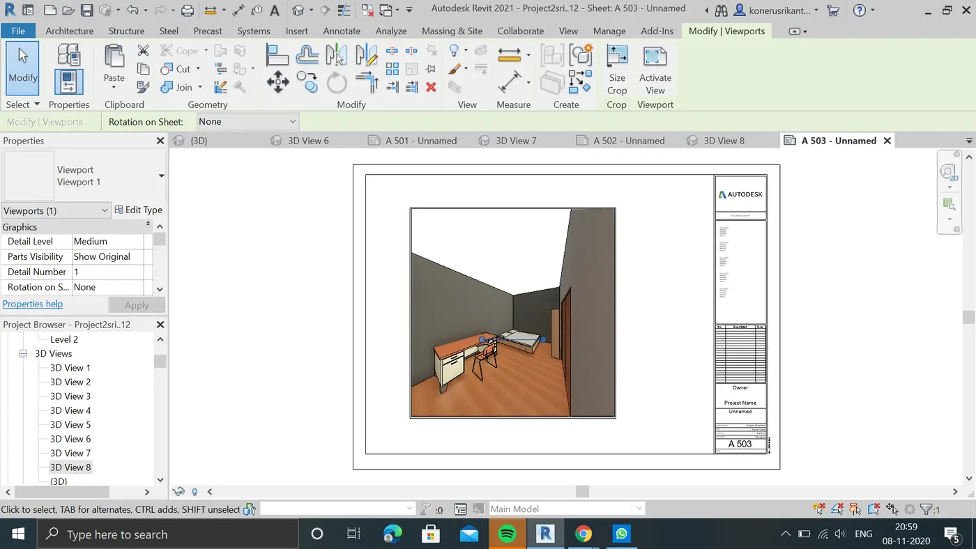
result: all the camera views are created in sheets succesfully.