REVIT_creation of basic drawing_week2
1.BIM stands for building information modeling.cad is used for industrial design of mechanical and electrical assembels.while bim is used in the design and constraction of commericial buildings such as airpots,office etc.BIM model will allow for cad image to be viewable in full detail at one particular zoom level .cad files lack and failing to self correct as adjustments are made to the model.
2.AIM:To Understand the concept of Categories, Families, Elements, Instances in Revit. Go to Insert Tab, choose a category. Pick a family and element. Understand the instances and insert it to Revit model.
PROCEDURE:
STEP1
A: open the insert tab in menu bar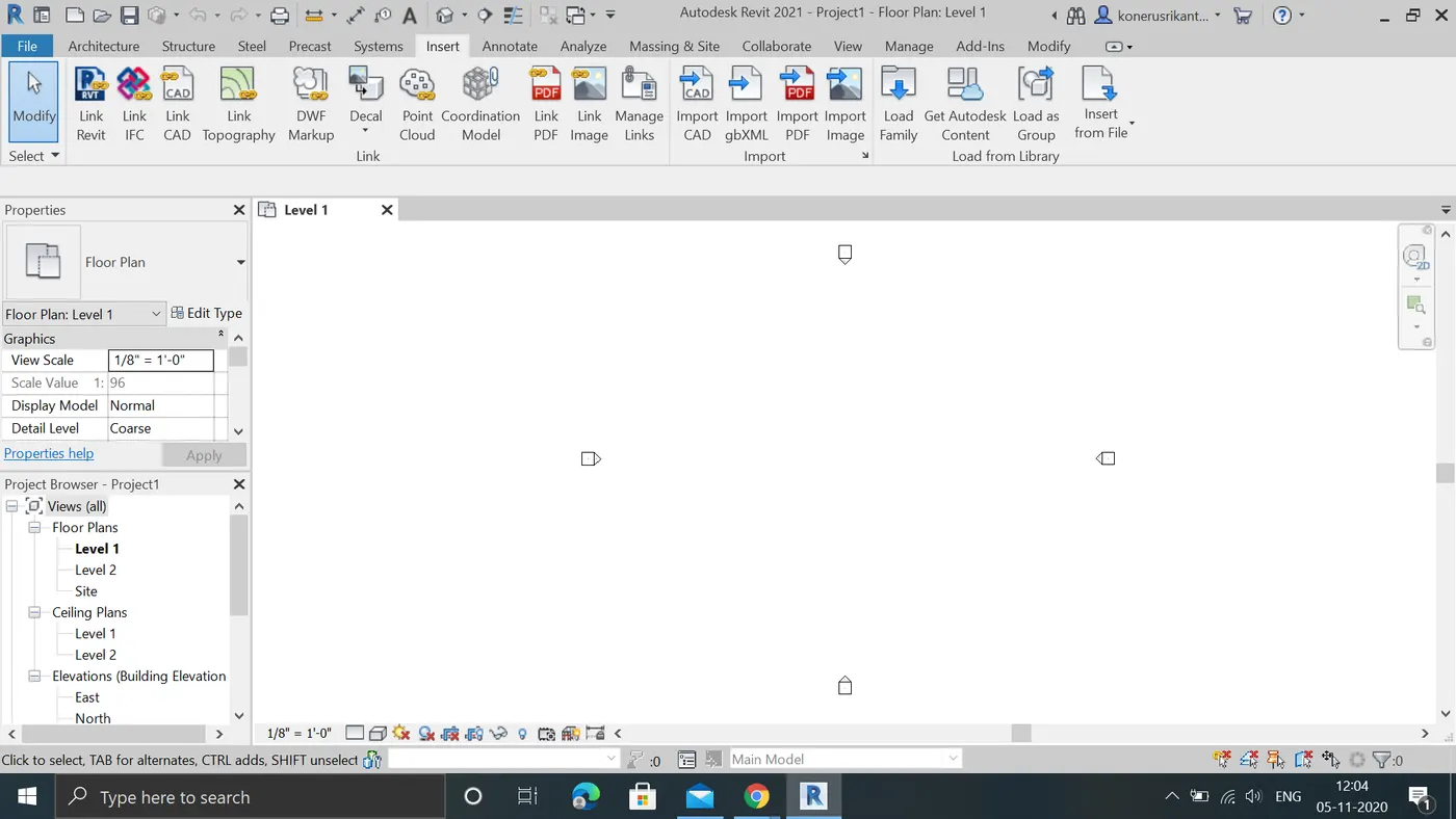
B:CLICK on the load families 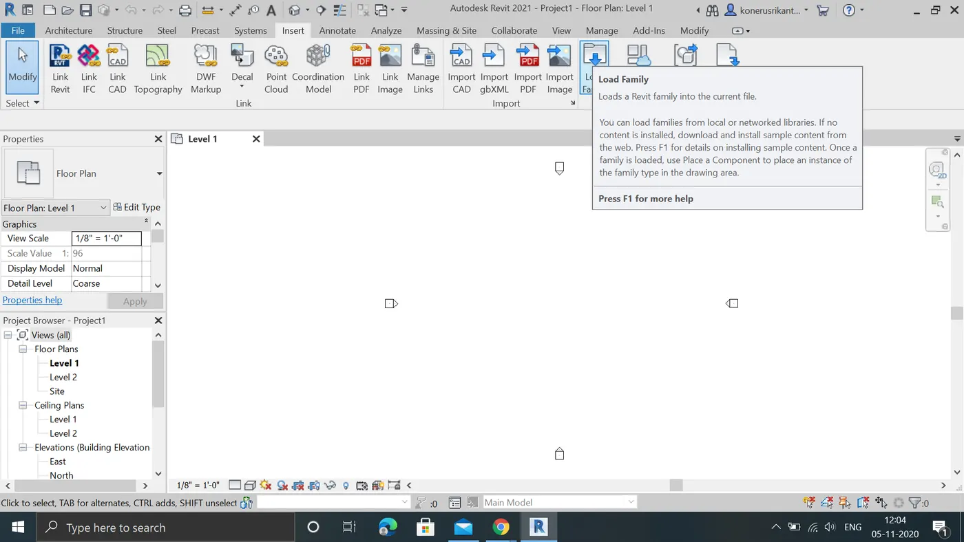
C:WE can find group of categories of elements in load faimilies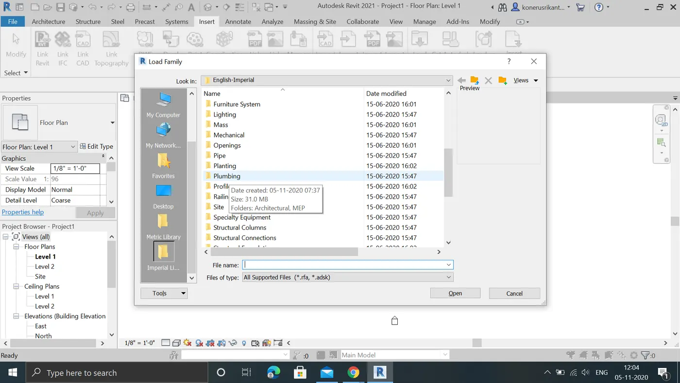
D:By opening categories we can find families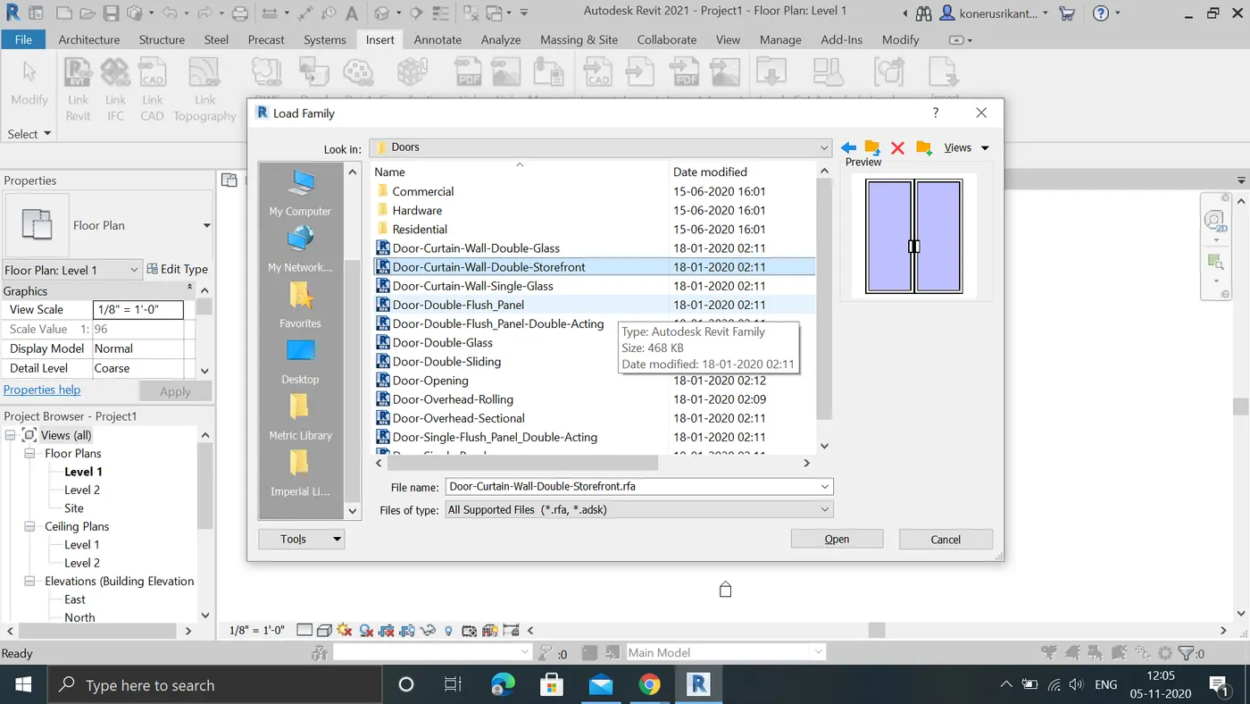
E:by opening it we can find elements
STEP2:
A:BY selecting required elements it will load in properties
B:by selecting door and open in properties we can find our element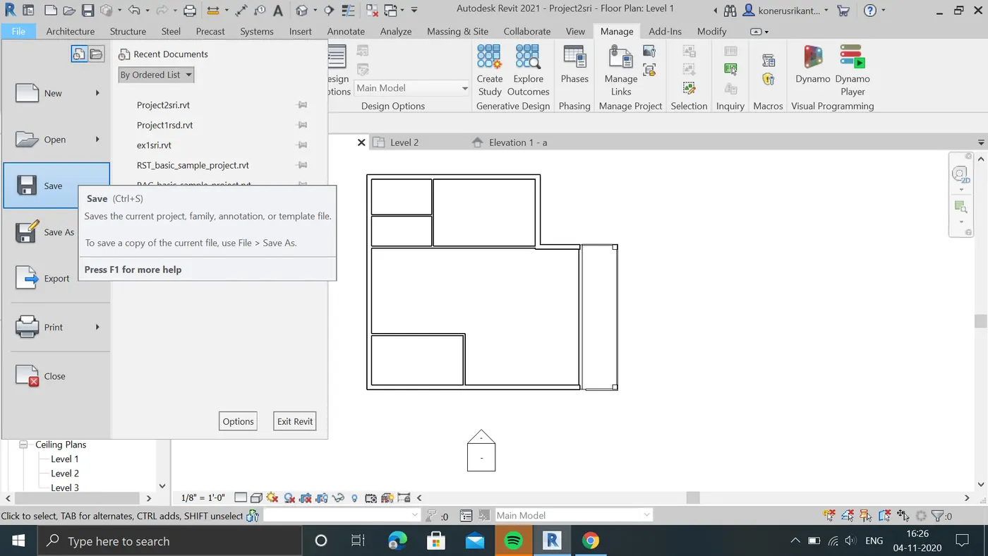
C:we can modify our elements
RESULT:we can insert group of elements by using insert tab to see in relistic view
3:AIM:TO Setting up a Project – Open a project file with architectural template and Save the file with appropriate name. Set up the project units to Imperial / Metric based on your convenience of modelling. Complete the project information under Manage tab. Set up the maximum backups for project file to 3
procedure:
STEPS1
A:open new project file and make it architectural template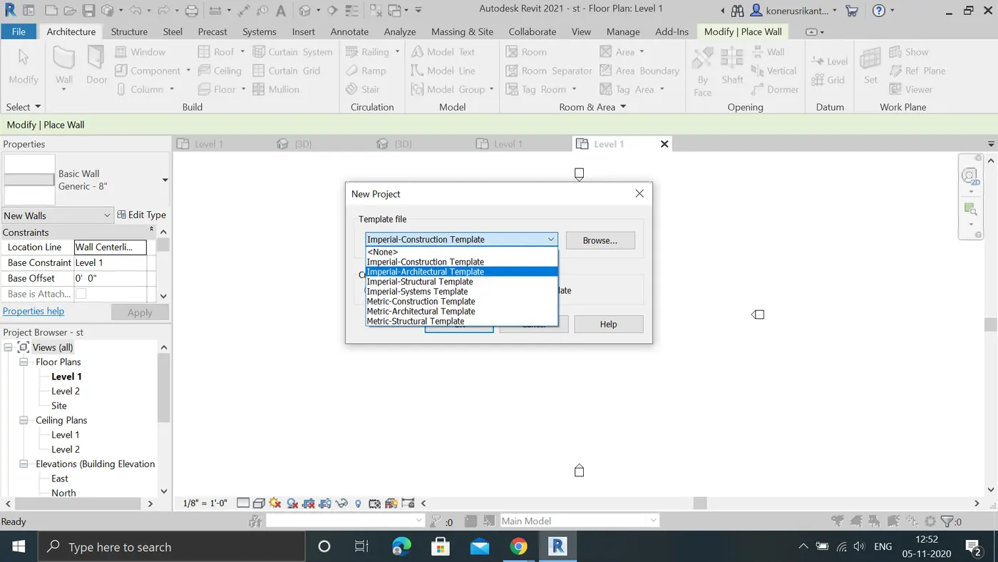
B:Save the file with required name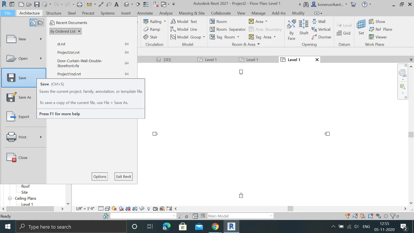
C:We selected imperial architecture so units are in IMPERIAL.we can change units in manage tabs into imperal/metric
D:WE add information to our project in manage toolbar by openig project information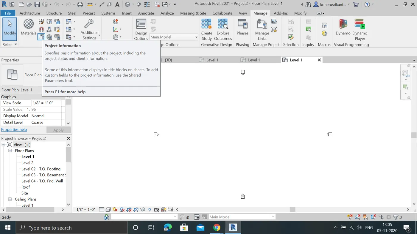
E:BY opening it we can add our informatin like org,author,issu date etc.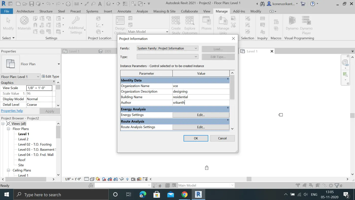
F:WE can project backups in saveas tab in File menu.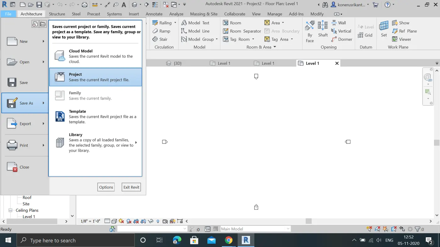
G:Click on project we can find window opened we can find optionstab below right corner by opening it we can manage our backups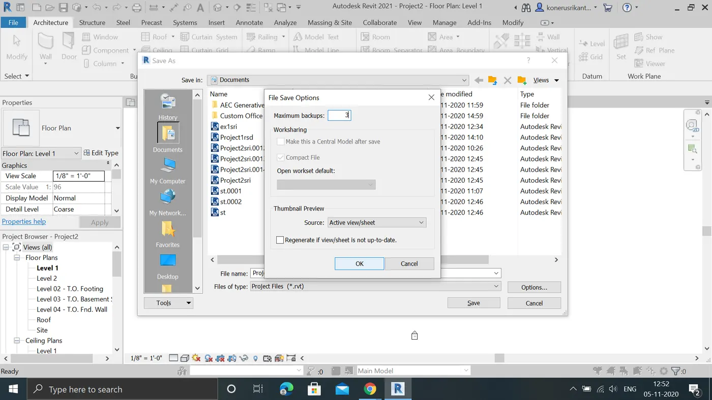
Result:by these we can manage our backups and we add our informations to projects and switch into reuired units
4:AIM:To Understand the concept of Levels and Grids. Follow the naming and conventions. Create the following Levels: ( Convert to metric equivalents if metric is your units)
Ground Floor @ 0’
First Floor @ 10’
Second Floor @ 20’
Roof @ 30’
Procedure:
a:open the architectural template.
c:new drawingpaper will appear
d:now open the elivations tab in toolbar
e:you will find elivations option in project browser open any one directon you will get level lines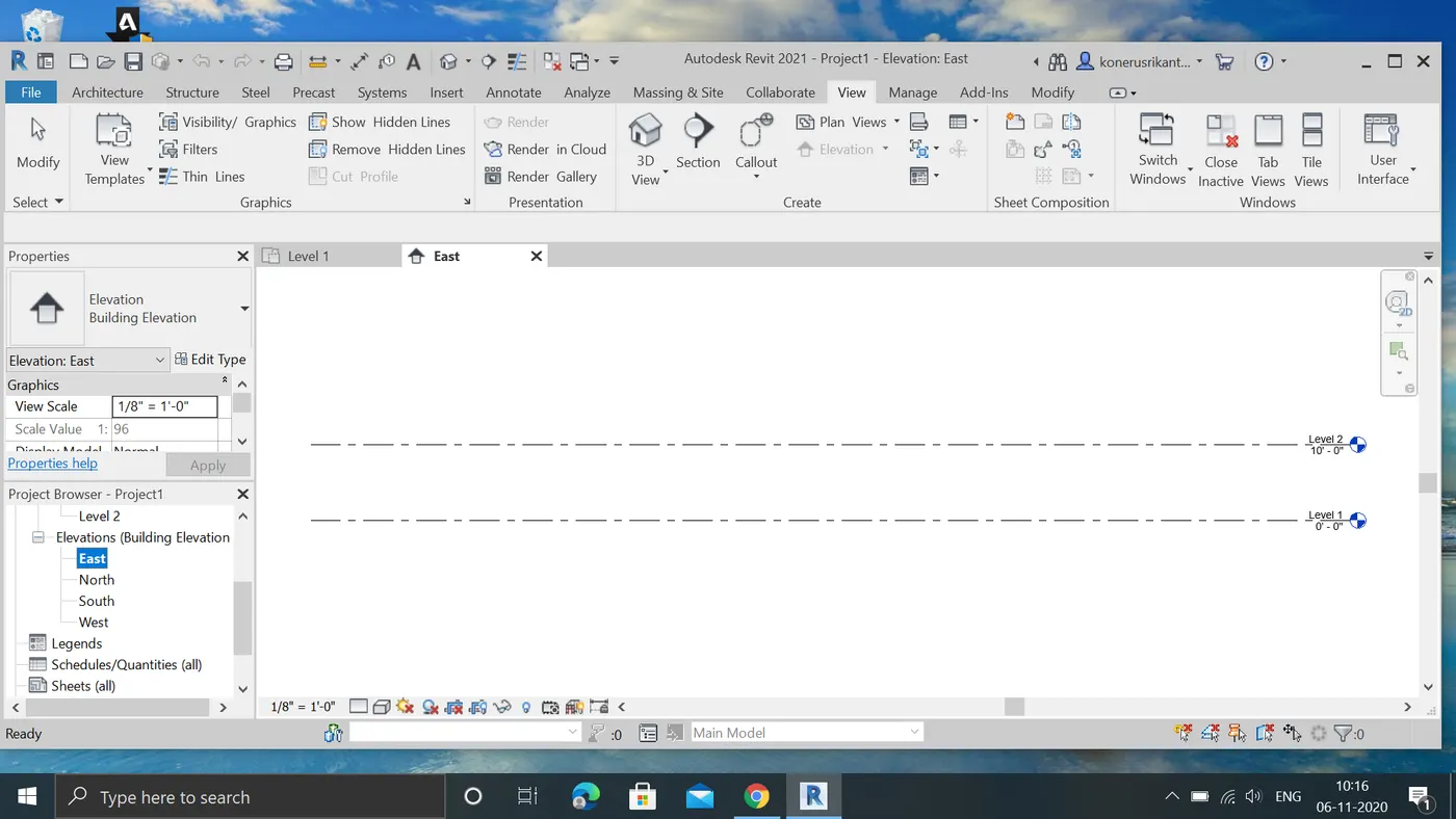
f:we can add required number of level lines by levels in datum toolbar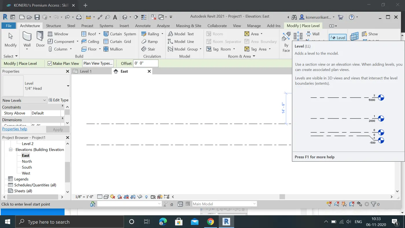
g:we can rename it like,floor,roof,etc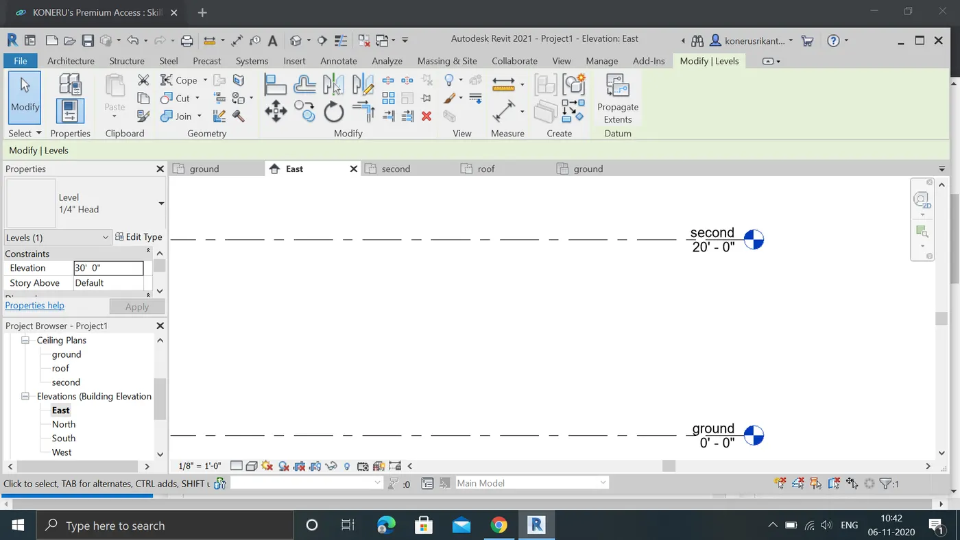
part2
procedure:
a:open a new architectural template
b:in menubar select the grid tab in datum toolbar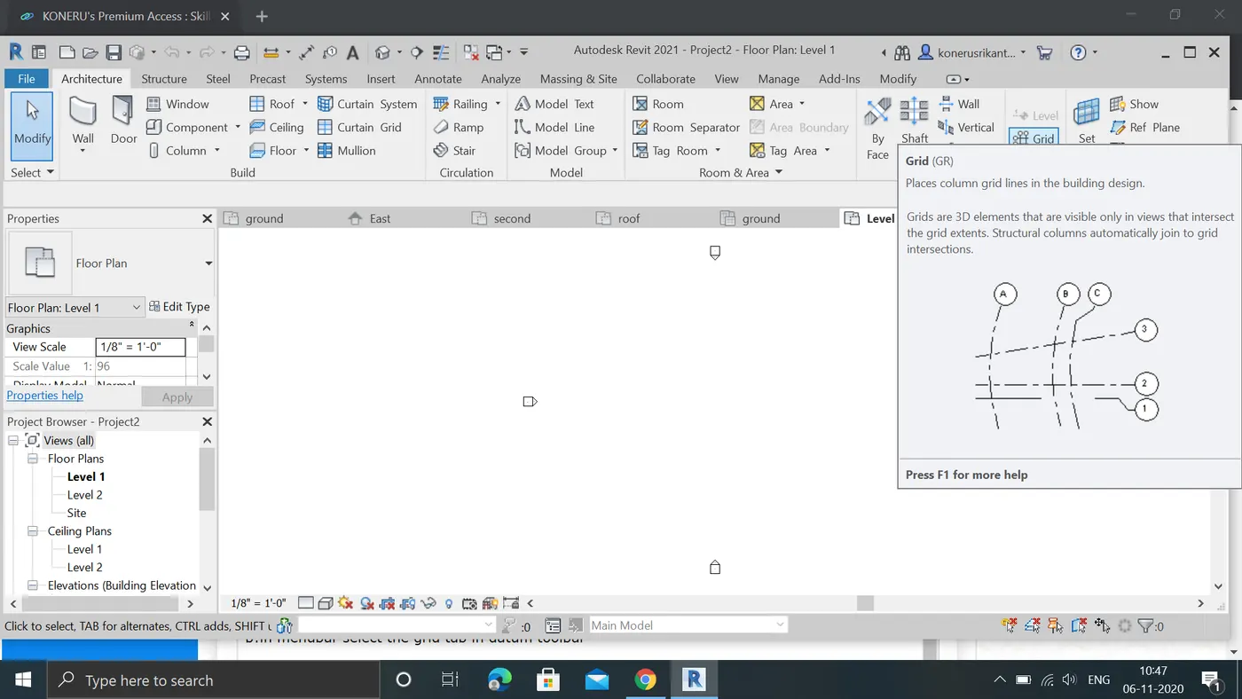
c:by opening it we can draw horizental nd vertical grid lines
d:draw horizental gridlines by 10'0"distance between them and name a,b,c,d..in alphabetical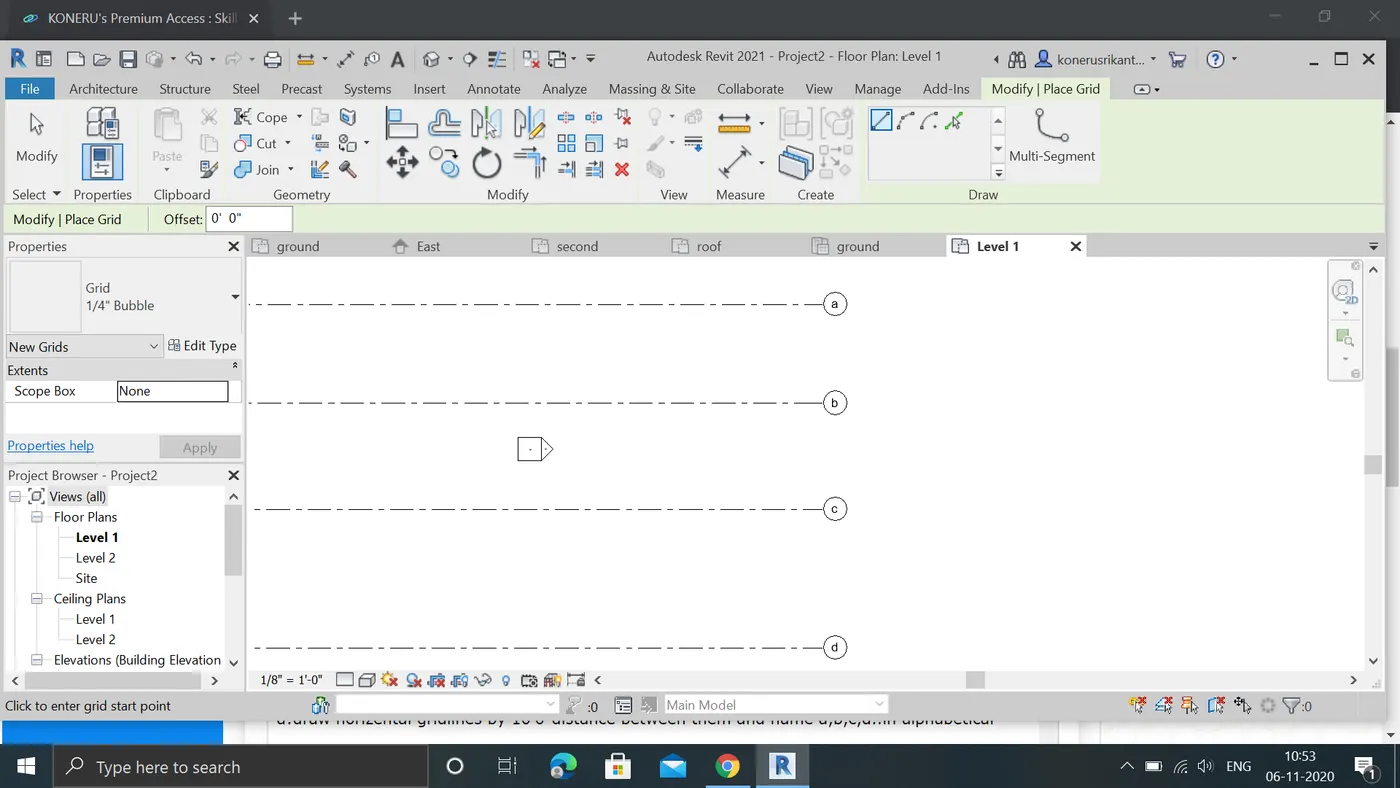
e:now draw vertical grid lines by20' distance betweenthem and name 1,2,3,4....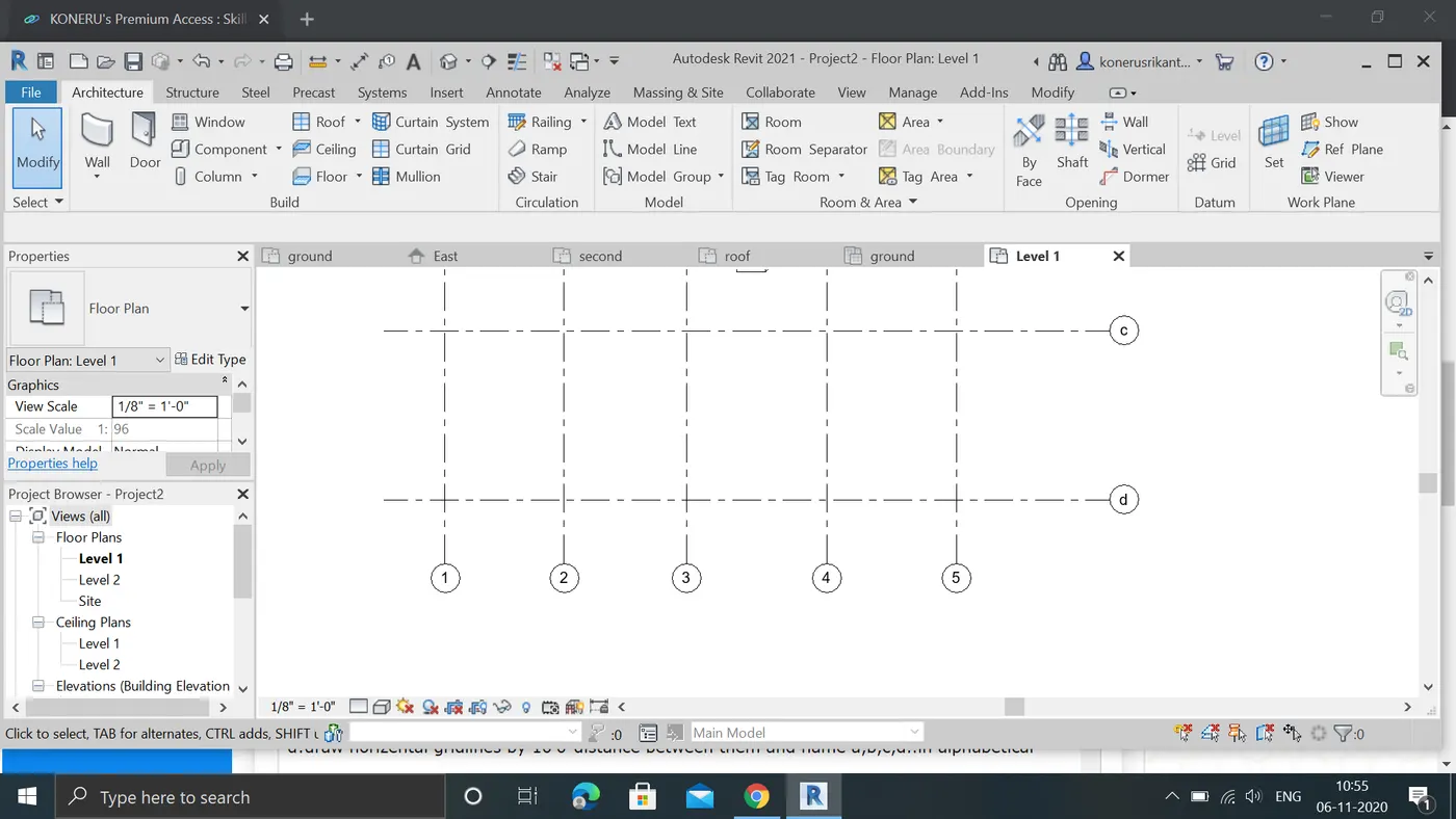
RESULT:required level lines and grid lines are constucted succesfully
5:AIM:TO draw 3D modelling of residential unit – From looking at your house / or a place you aspire. Create a conceptual layout of the residential unit. You can measure using a tape or
you can access your residential plan to create a similar layout.
procedure:
A:draw a residential layout with architectral template 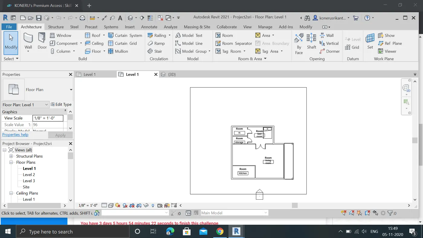
B:now draw interior walls to layot
C:NOW CLICK view to see in 3d view
d:Now open graphic display option to see in realistic view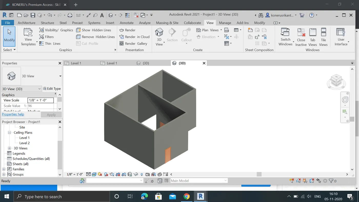
E:Now we add dimensions in annotation tab by aligined tab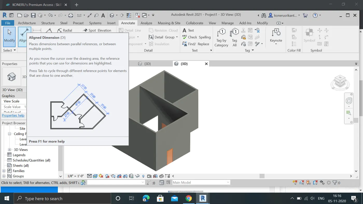
Result:CREATED COCEPTUAL RESIDENTRTIAL LAYOUT IN 3D VIEW SUCESSFULLY
6:AIM: In the layout created draft the level of details you are planning to include – Dimensions of room, components you plan to add in the residential unit.
Procedure:
a: in the layout open the levels in the elivations in projectbrowser
b:open any direction elivation east,west,north,south,
c: we can view the elivations click on the wall and drag it to required level
d:similarly repeat for all wall,all elivations should be same height
e:we can see the elivations 3rdview of required walls
f:measure the directions in annotation tab and select the linear
g:now measure the dimensions by clicking on the end points of required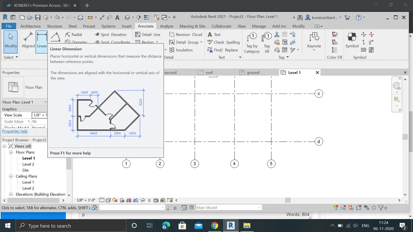
result:drfting of levels ,dimensions are excuted succesfully
7:AIM:To Identify the residential model elements such as Door, Windows, Tables, Chair, Couch, Bed, Lamps from the library and insert them to the model . Save the project for use
for Assignment 3
PROCEDURE:
A:draw a plan with required template
B:NOW open insert menu and click load families
C:Open load families select the reqired categories of famalies
D:N0W open required elements to add in to project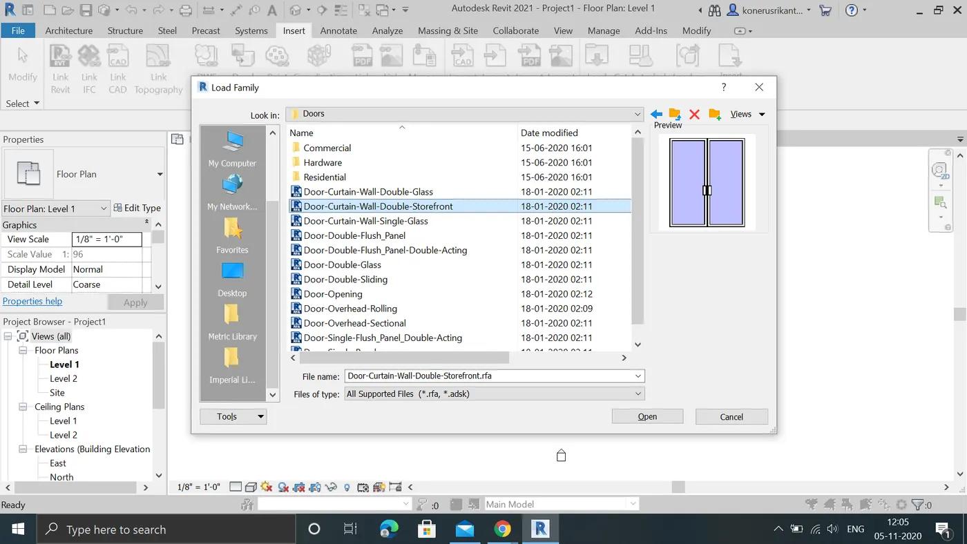
F:All THE elements are loaded in properties in families tab by dragging in to layout we can add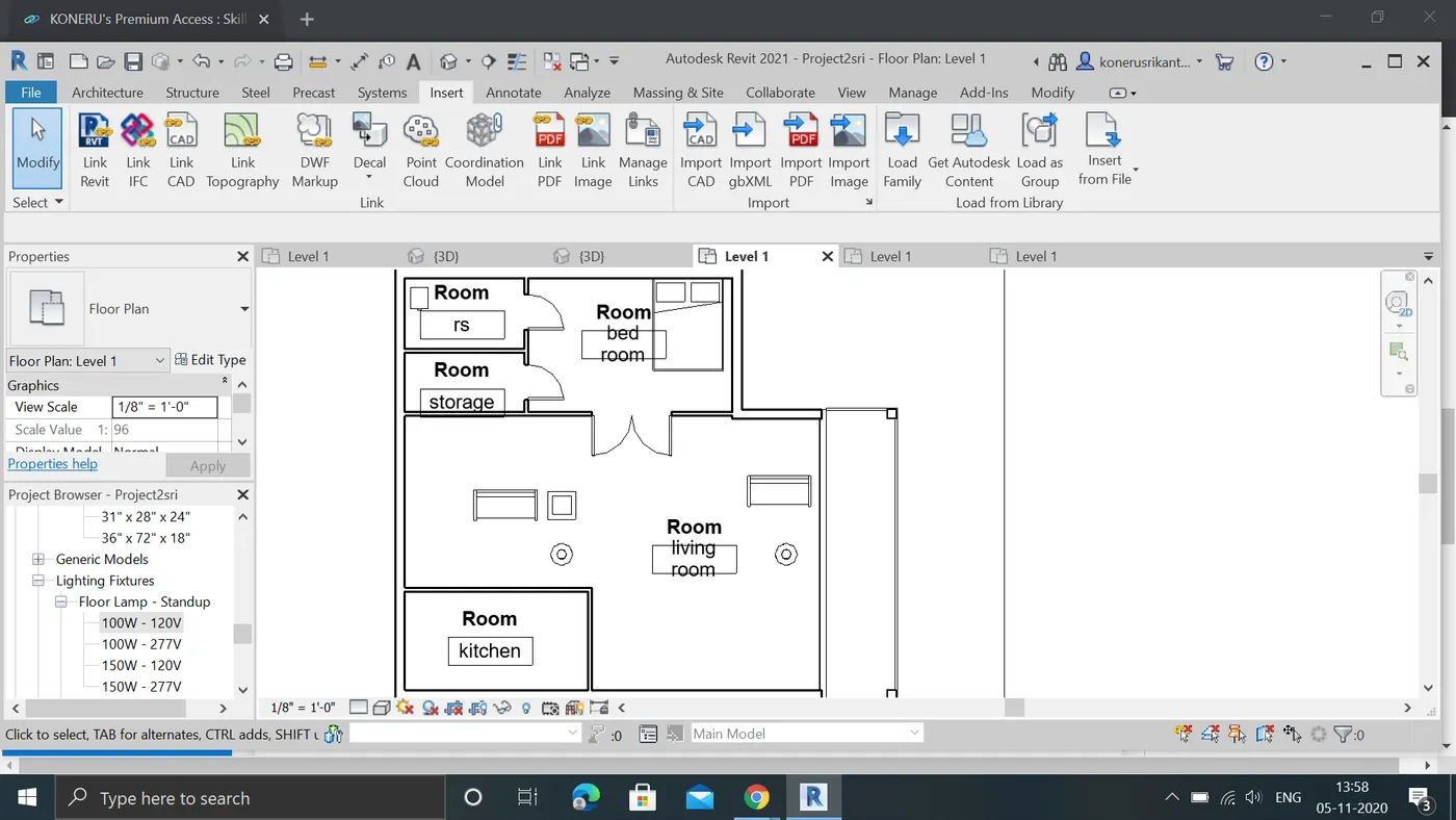
RESULT:Sucessfully added required elements to the project and added information to project and saved it