Project 1- Generating shell mesh for instrumental panel of the car according to given quality criteria in ANSA
Objective- To mesh the instrument panel component according to the quality criteria given and also assign the thickness to the components.
|
S.No |
Quality Criteria |
Value |
|
1 |
Target/Average length |
4 |
|
2 |
Minimum Length |
2 |
|
3 |
Maximum Length |
6 |
|
4 |
Aspect |
3 |
|
5 |
Warpage |
15 |
|
6 |
Skewness |
45 |
|
7 |
Jacobian |
0.7 |
|
8 |
Minimum Quad Angle |
45 |
|
9 |
Maximum Quad Angle |
135 |
|
10 |
Minimum Tria Angle |
30 |
|
11 |
Maximum Tria Angle |
120 |
| 12 | Tria % |
15 |
Procedure:-
- Open ANSA and open the component file which is in ".igs" as provided.
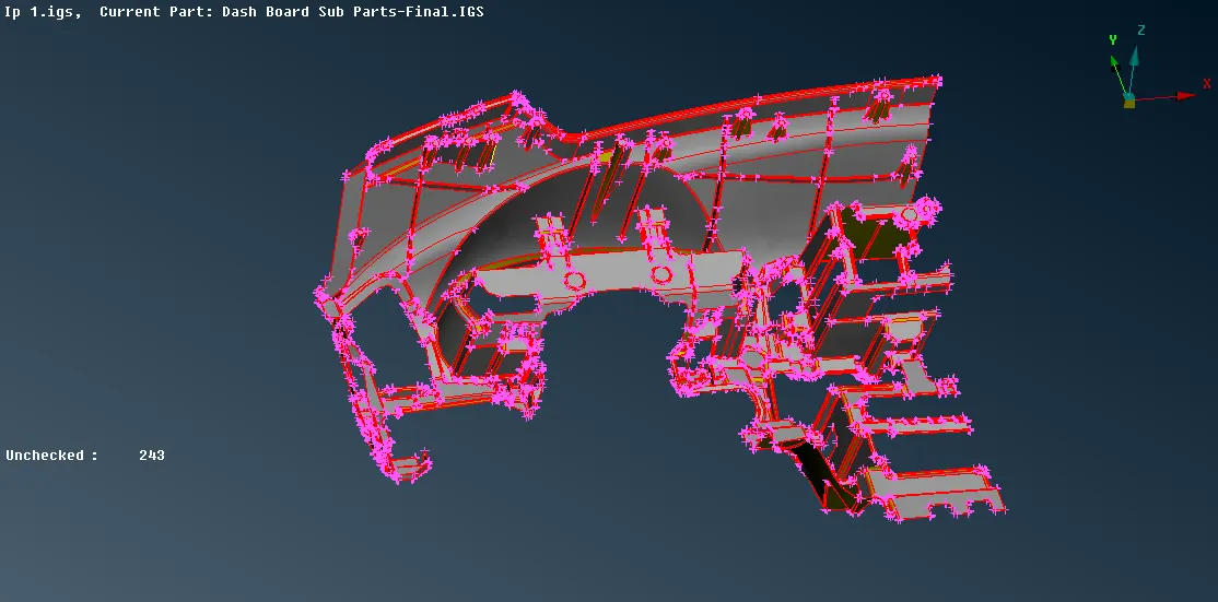
- From the modules use topo, Topo -> Faces -> Topo -> select the entities.
- Also even the orientation of the component by using the "Orient" option which is under Modules -> Topo -> Faces -> Orient
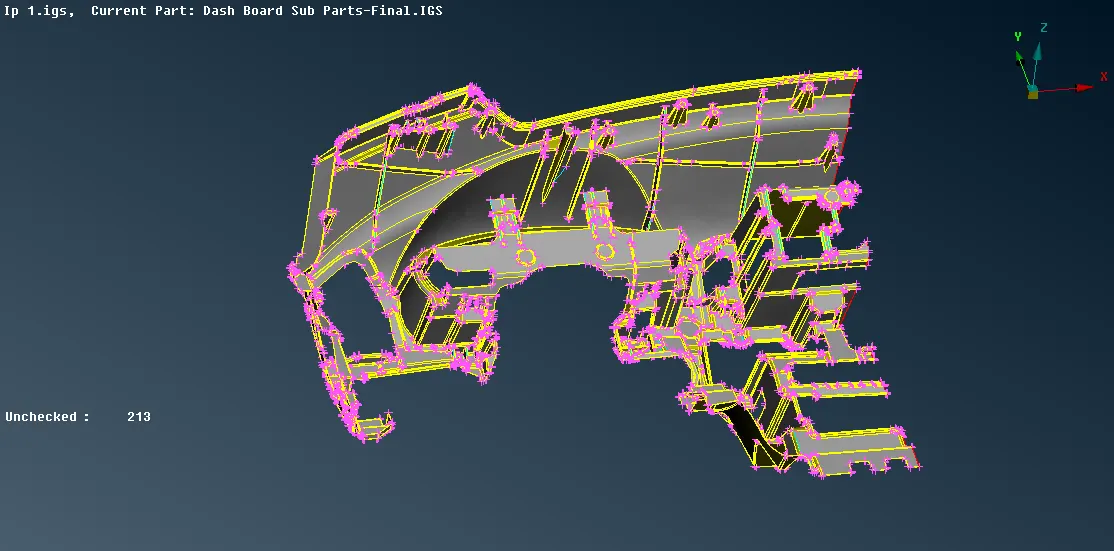
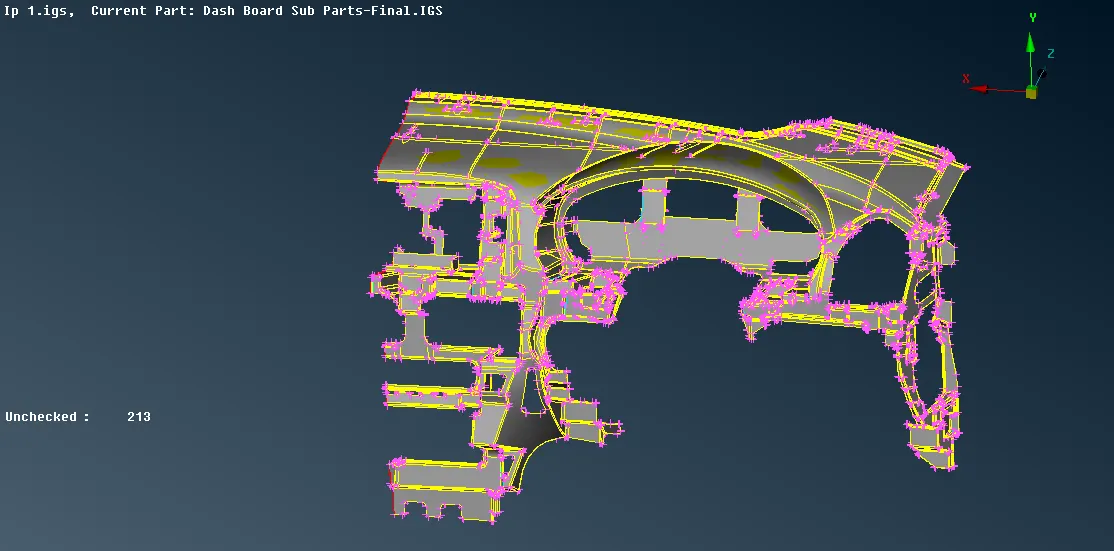
- Now check the entities for any geometrical error by using the "Geometry" option from the Tools -> Check -> Geometry (from the options select single cons also). If any error found it can be fixed automatically by right click on the error and click on the fix or it can be solved manually by using different options of "Topo" present in modules.
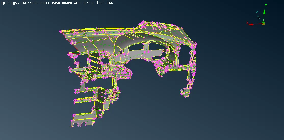
- From the "Utilities" menu, use the "measure" option to check the thickness of the component, as the component has ribs on one side which vary in thickness so the midsurface of the component and ribs has to extracted manually and assign respective thickness.
- First, extract the midsurface from the base surface side which do not have any ribs by using Modules -> Topo -> Faces -> offset. After extracting midsurface set PID by using Modules -> Topo -> Faces -> Set PID, as the component have a variable thickness so PID should be assigned to each extracted midsurface so that desired thickness can be provided.
- Check the extracted midsurface for any deformation or missing parts in between and also check for any geometrical error by using the "Geometry" option from the Tools -> Check -> Geometry (from the options deselect single and triple cons ). If any error found it can be fixed automatically by right click on the error and click on the fix or it can be solved manually by using different options of "Topo" present in modules.
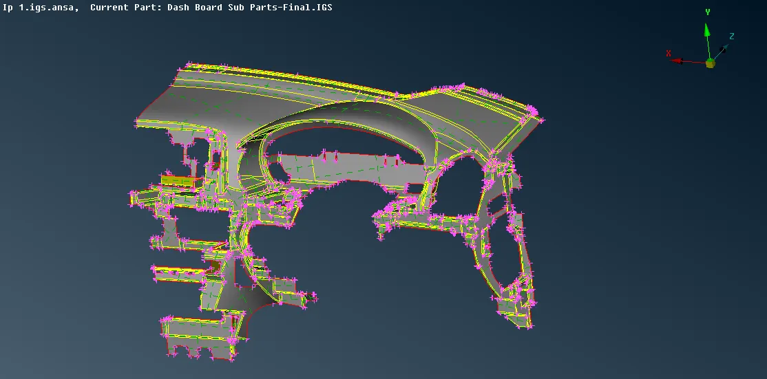
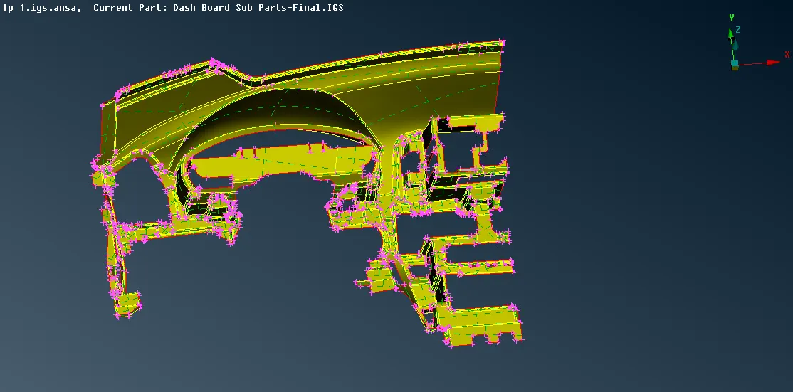
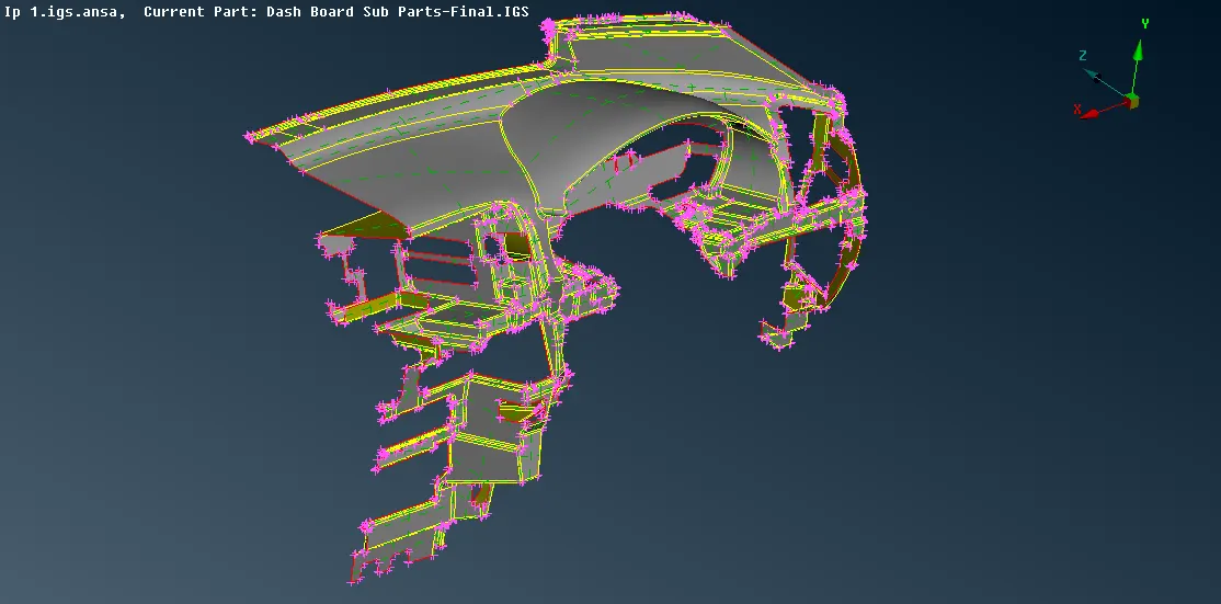
- After extracting the midsurface from the base surface side, midsurface for ribs should be extracted and as all the rib do not have the same thickness so accordingly different PID should be assigned to the respective rib.
- Midsurface of ribs can be extracted by first getting the middle curve from the surface construction line by Modules -> Topo -> Curves -> Middle -> Select the 1st construction line -> middle mouse click to accept -> Select the 2nd construction line -> middle mouse click to accept and generate the middle curve.
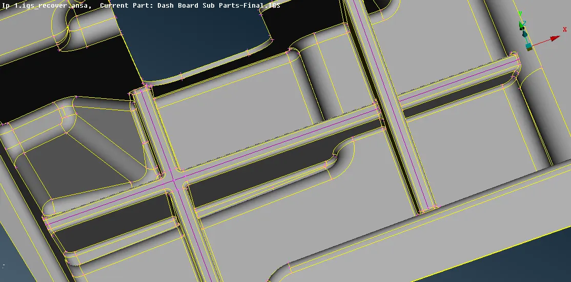
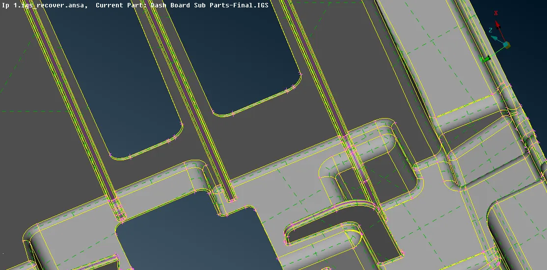
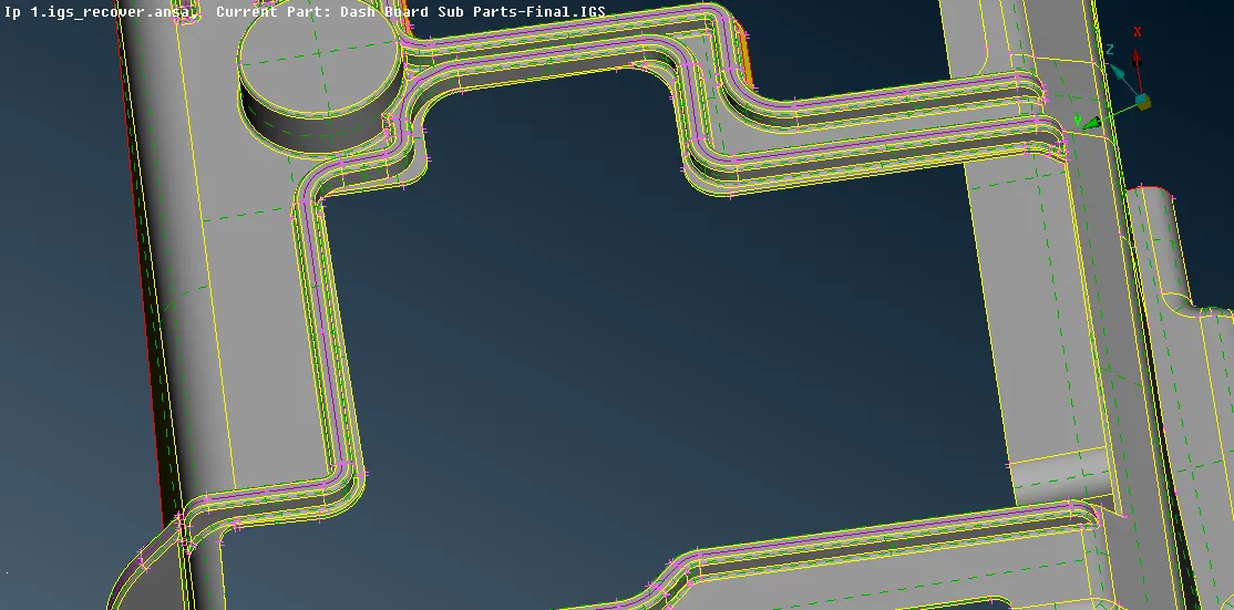
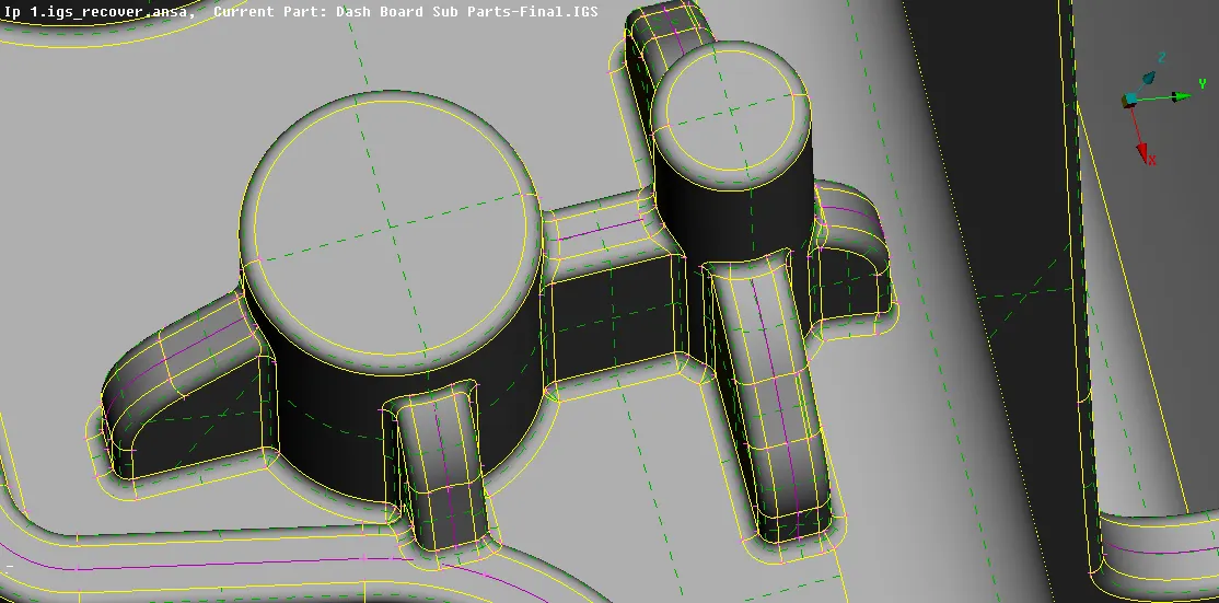
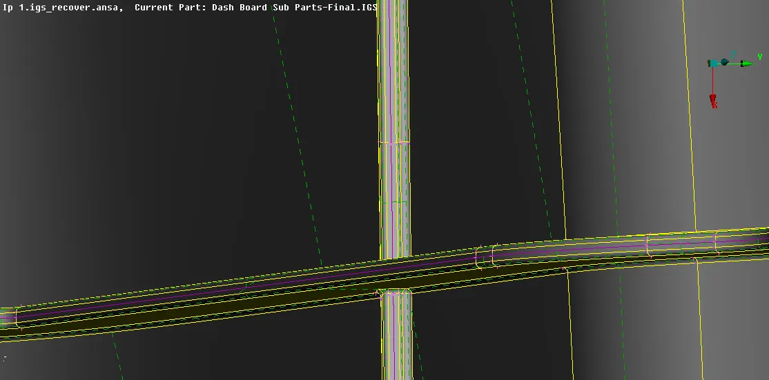
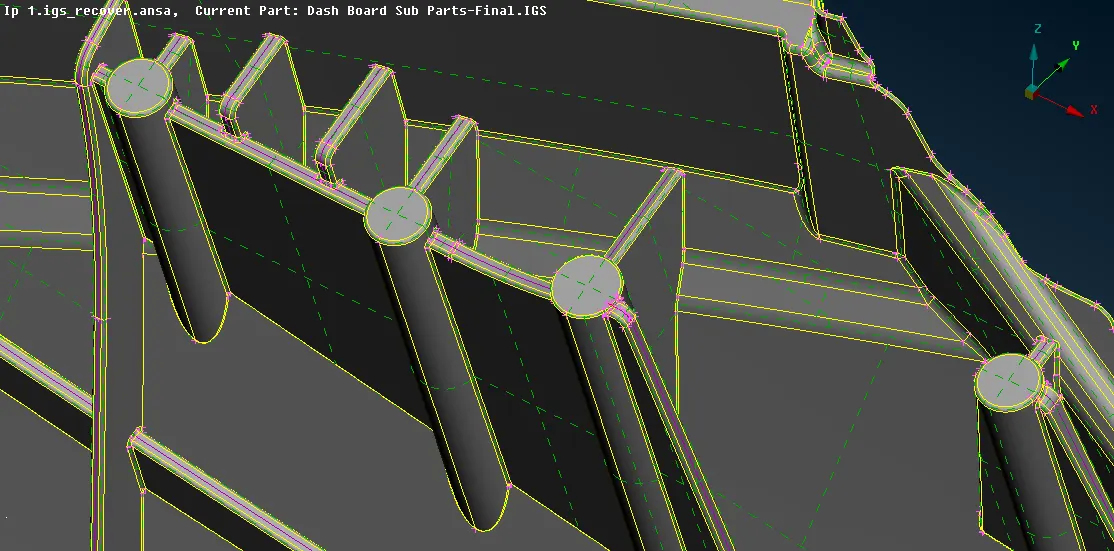
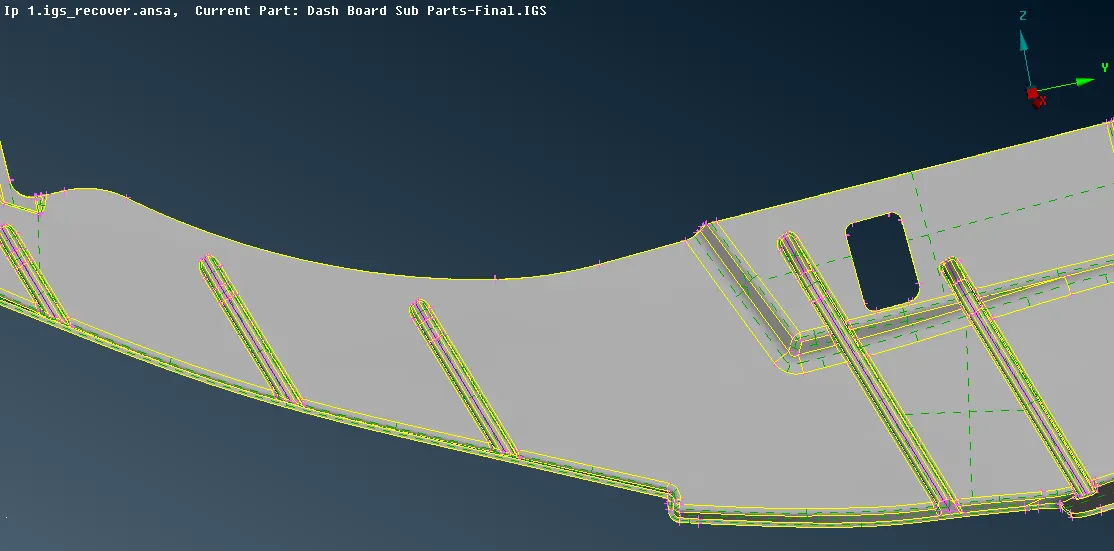
- After generating the middle curve from the rib's construction lines surface should be created using the obtained middle curve by Module -> Topo -> Faces -> New -> Fitted, but before creating the surface check the thickness of each rib so that PID can be assigned while generating surface itself.
- Connect the newly generated rib midsurface to base midsurface by using Module -> Topo -> Faces -> Extend also for ribs which are intersecting each other use Module -> Topo -> Faces -> Intersect to generate the triple con.
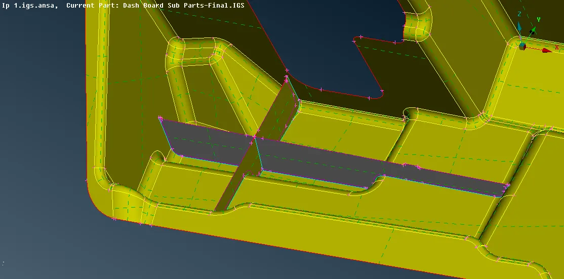
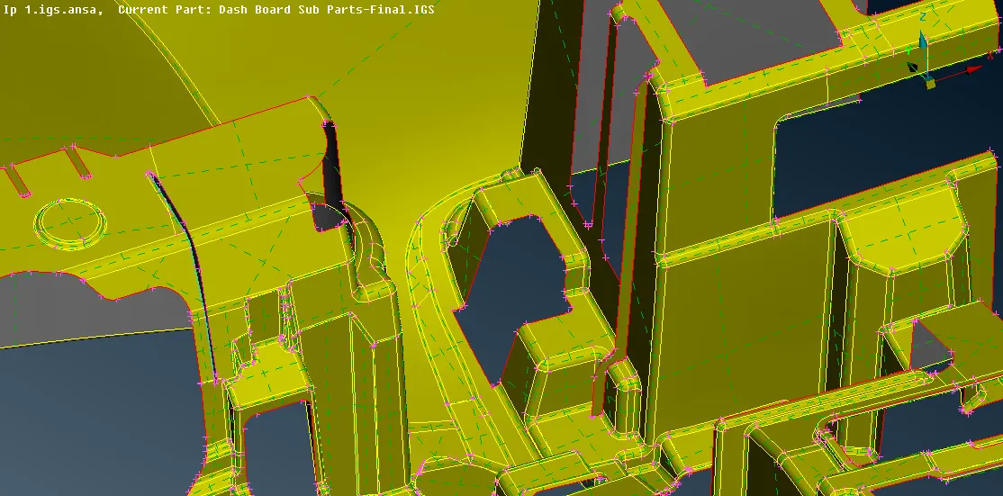
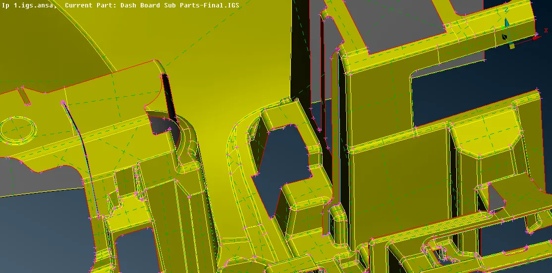
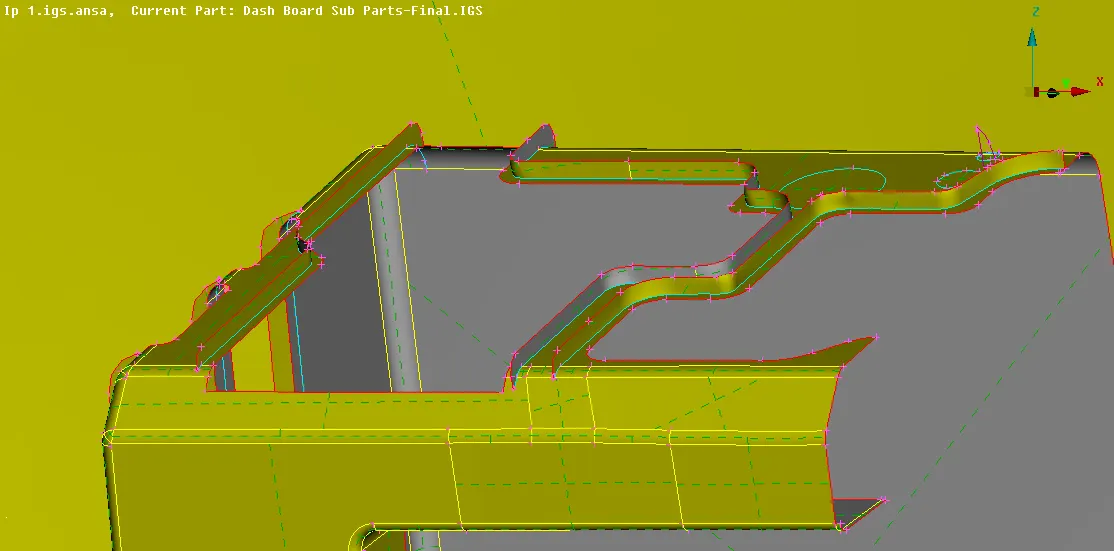
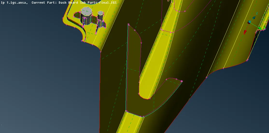
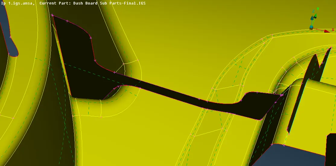
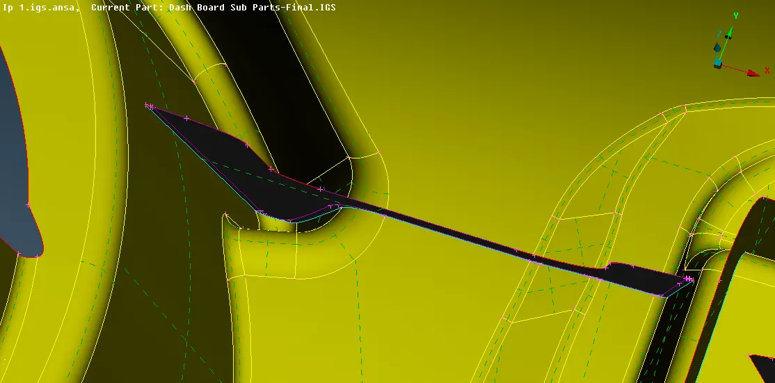
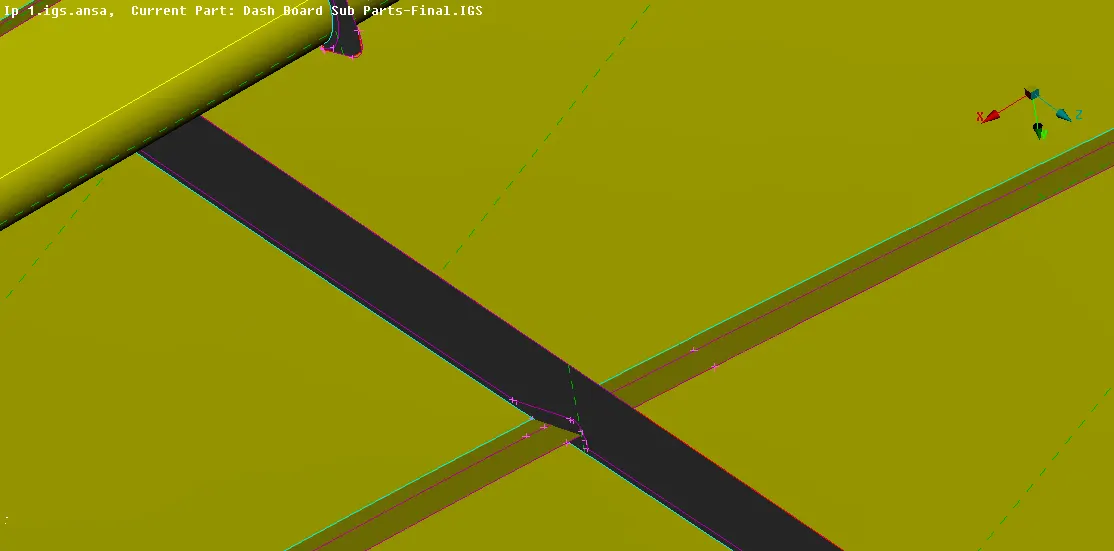
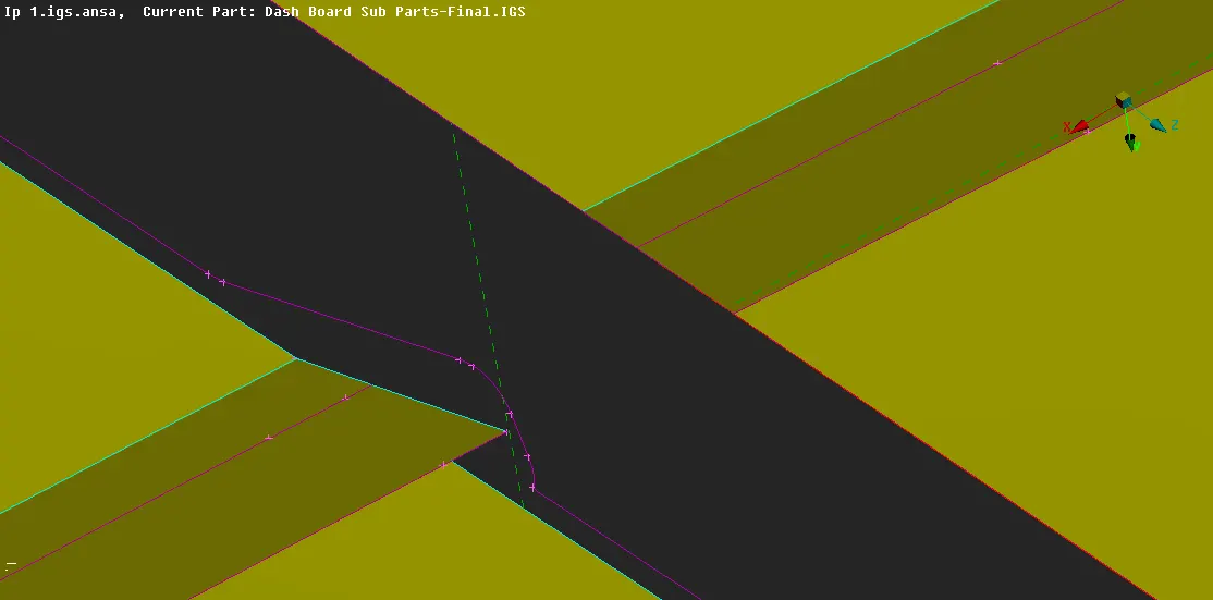
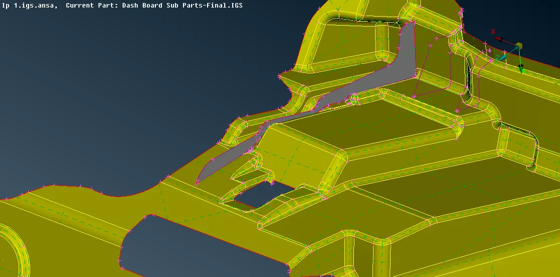
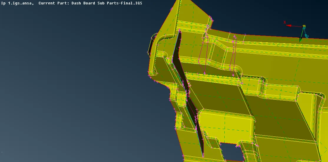
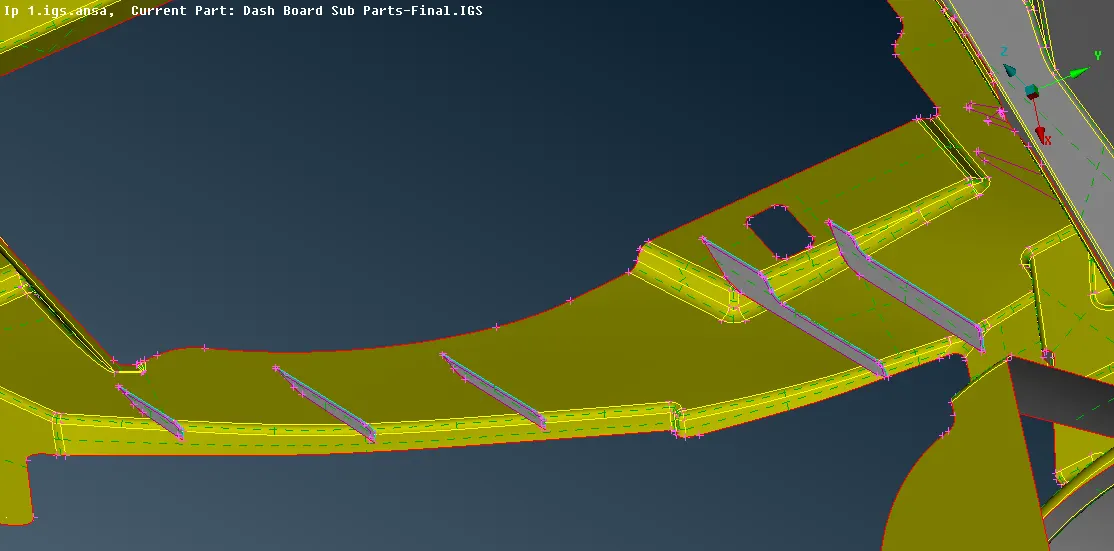
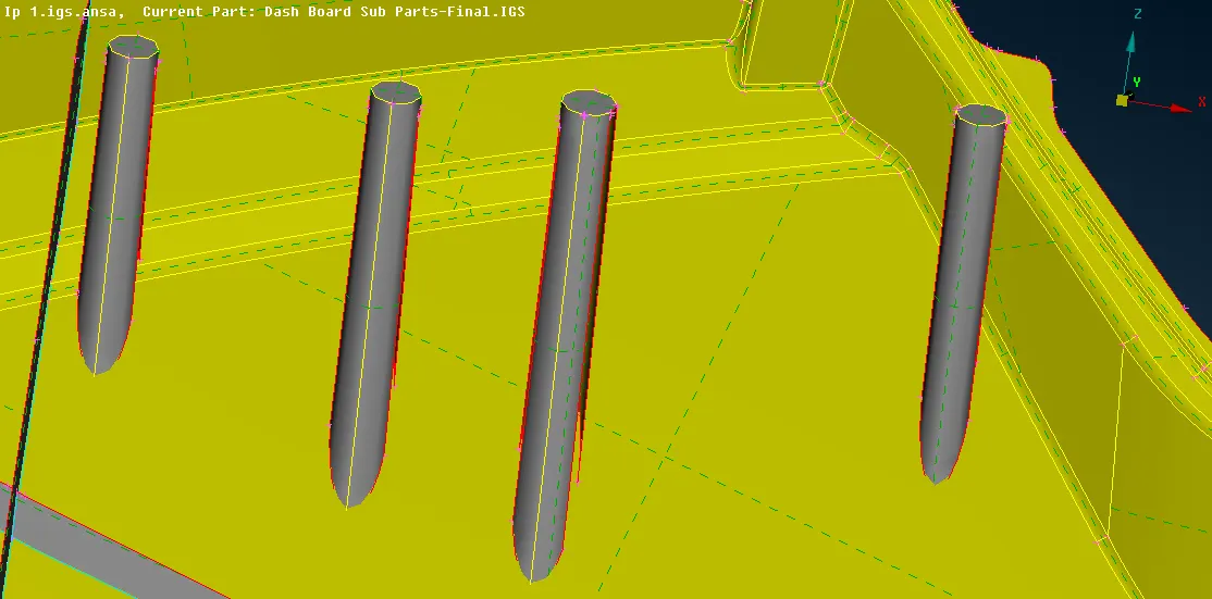
- After extracting all the ribs the surface for locator should be generated and as the locator present are solid so offset the locators to 0.5 inward i.e -0.5 distance and assign different PID for the locator by Module -> Topo -> Faces -> Set PID, after offsetting extend the edges of locator to the base midsurface also wherever the ribs are connected to the locators extend the ribs accordingly.
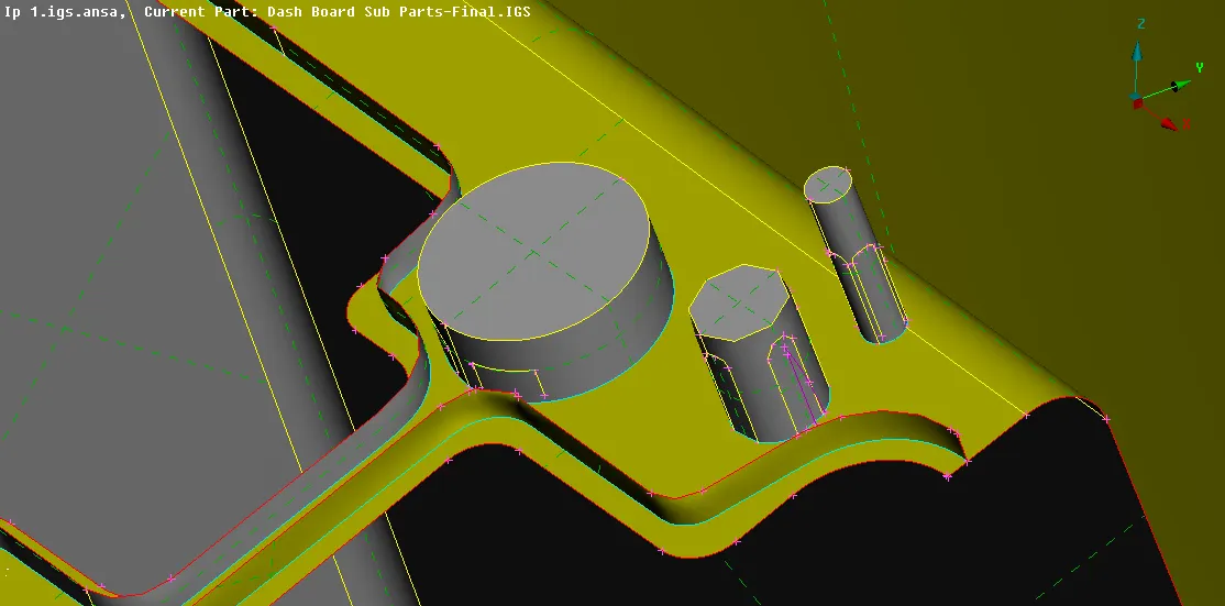
- After offsetting the locator close the side edges by generating new surface by Module -> Topo -> Faces -> Fitted.
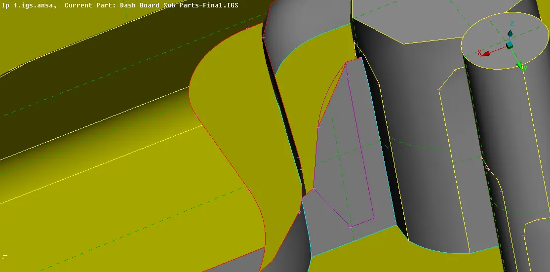
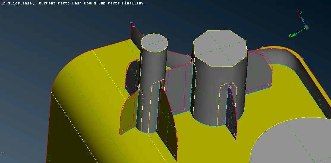
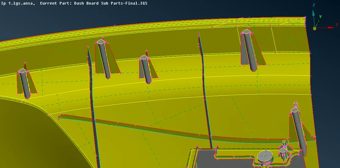
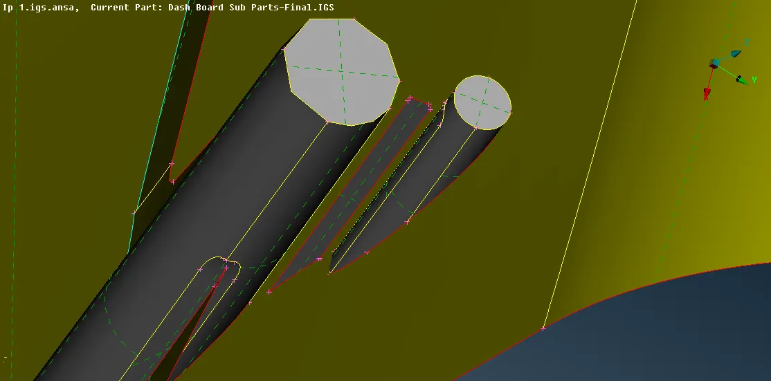
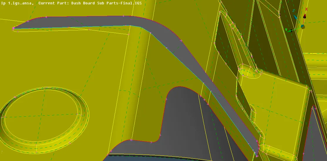
- The ribs surrounding the locators are extended to the base midsurface after that the ribs can be connected to the locators by extending it by Module -> Topo -> Faces -> Extend -> Select the free edge to extend (red cons) -> middle click to accept -> select the surface to extend -> middle click to accept the extend, also the ribs should be extended to the base midsurface in similar process, if any surface is generated beyond the extended surface it should be deleted by Module -> Topo -> Faces -> Delete.
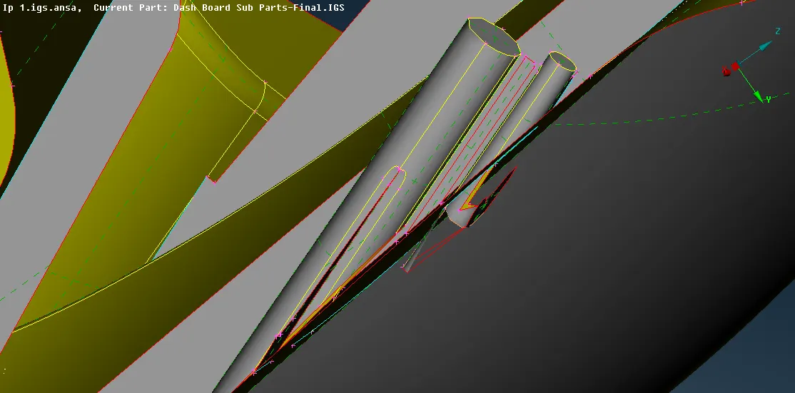
- As it can be seen that by extending the free edges of the locator the the base midsurface also created some distorted surface which should be deleted.
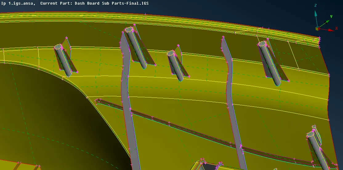
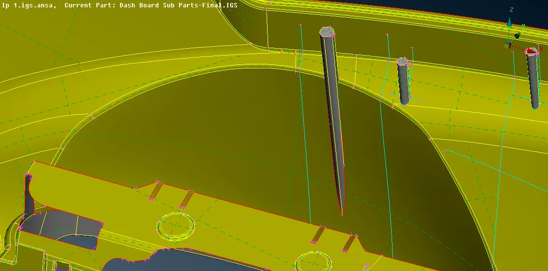
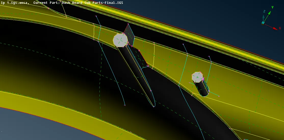
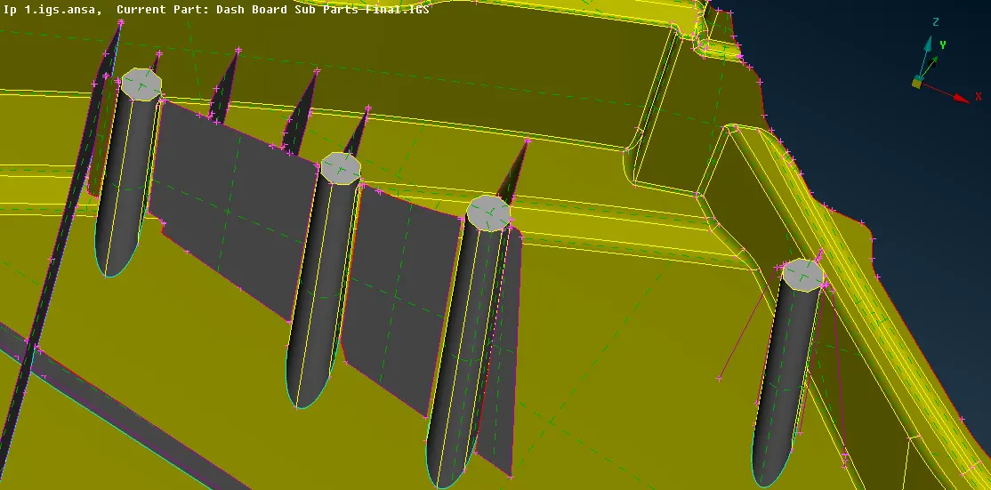
- The ribs midsurface are created by first extracting the middle curve from the parent surface and the new midsurface is created using the middle curve by Module -> Topo -> Faces -> New -> Fitted and than extended to respective surfaces.
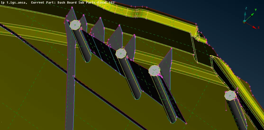
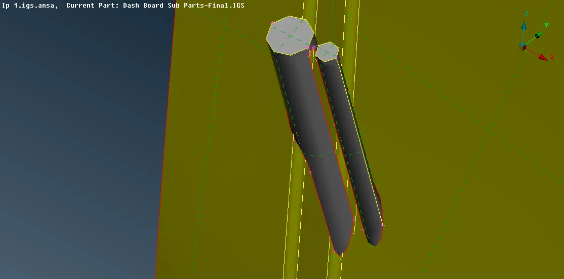
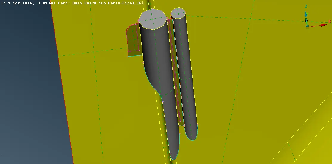
- The midsurface of the below shown part can also be extracted, first measure the thickness and accordingly offset the base to generate base midsurface.
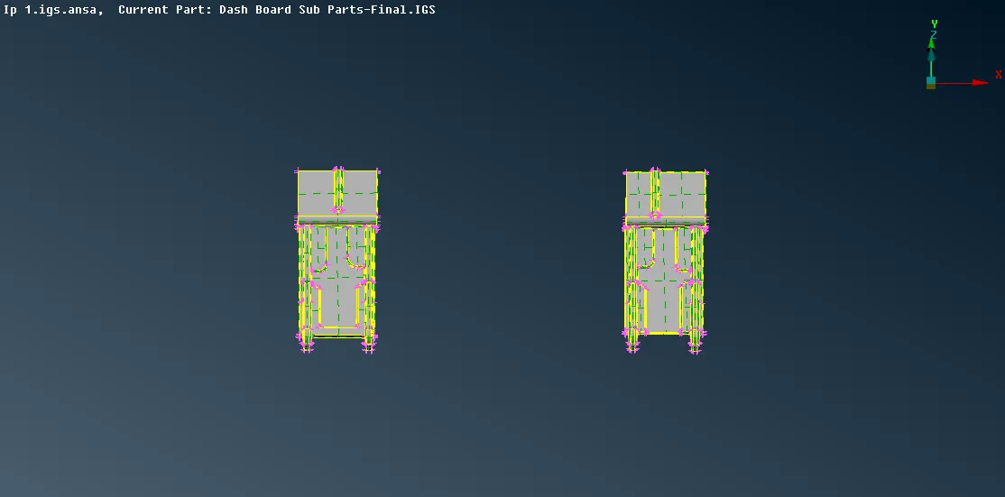
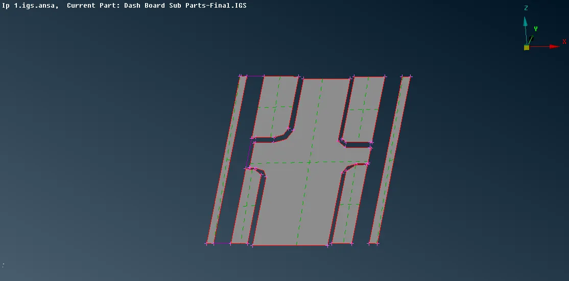
- Close the gaps by creating new surface Module -> Topo -> Faces -> New -> Existing Surface.
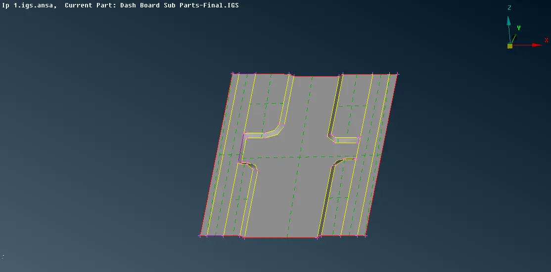
- The remaining part can be extracted by creating middle curve and by using the middle curve generate new surface.
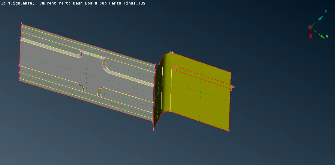
- Extend the surface to connect.
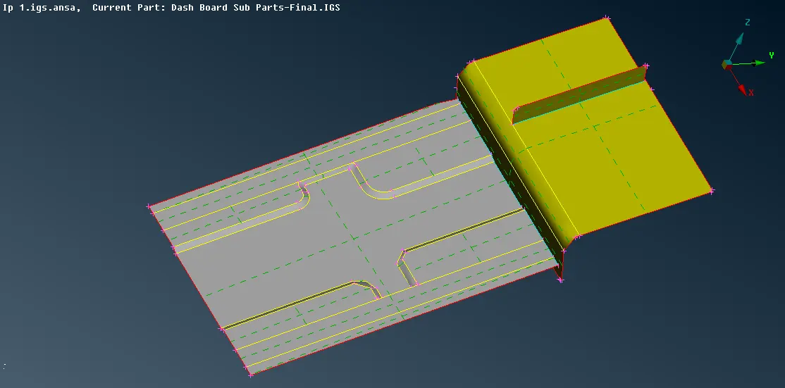
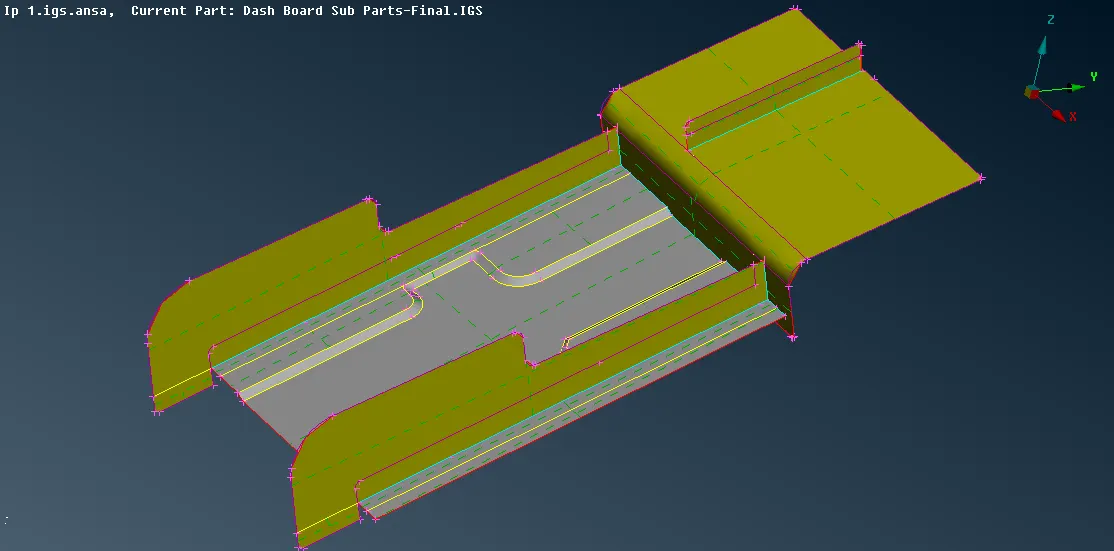
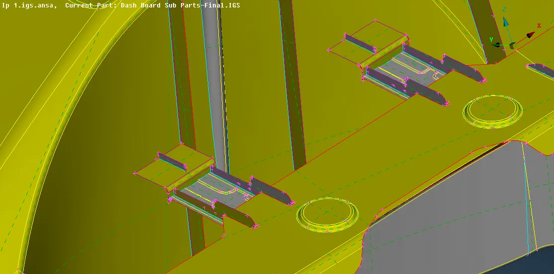
- The ribs can be connected to the main base surface by generating new surface using the free edges.
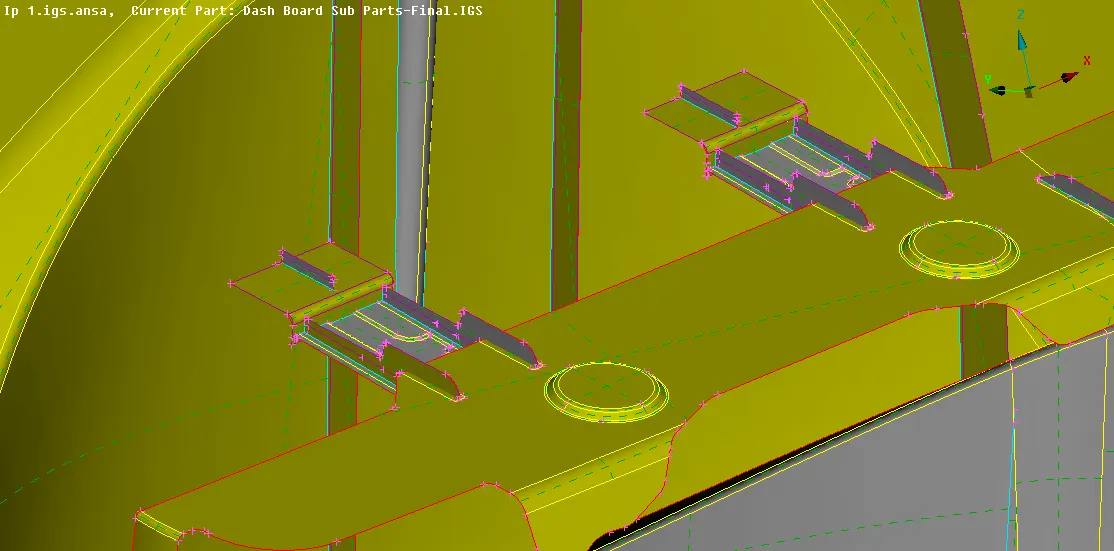
- As now all the midsurface of the component has been extracted and connected perform geometry check of the midsurface (uncheck single con and triple con), if any error found it can be fixed automatically by right click on the error and click on the fix or it can be solved manually by using different options of "Topo" present in modules.
- Before meshing can be done set the quality and mesh parameters by using "Quality Criteria" and "Mesh parameter" form the "Utilities". Also, set the length for the entities by Modules -> Mesh -> Perimeter -> Length -> for both Perimeter and Macro select the visible entities and provide the values.
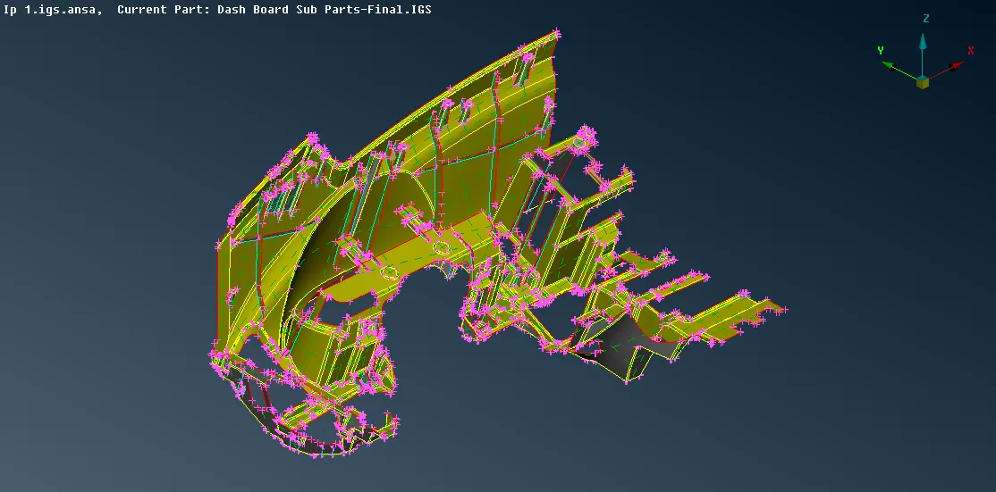
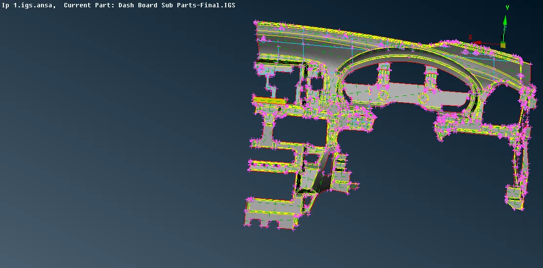
- Mesh the surface from one side so to apply mesh Module -> Mesh -> Mesh Generation -> Spot mesh -> select the surface to apply mesh.
- The elements can be remeshed and rotating quads and off elements can be removed by using the option in Shell Mesh -> Reconstruction or using the option in Elements -> Split, Swap or combination of the mentioned process.
- To refine the meshed surface use "Smooth" option present under "Shell Mesh'.
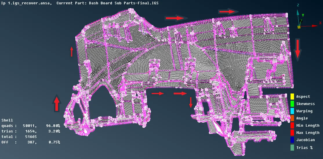
- Now to view the shell as solid elements, in Utilities -> Quality Criteria -> Presentation Parameters -> Elemets -> check Draw shell as solid -> Ok
Result:-
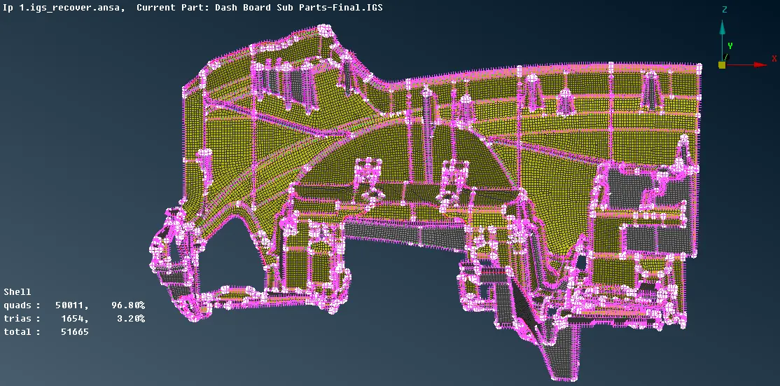
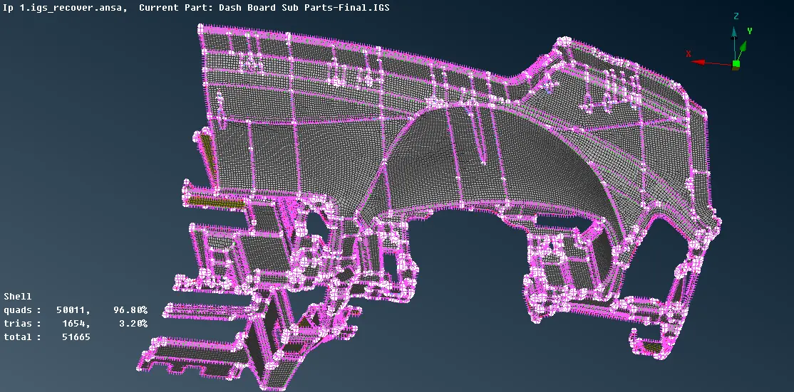
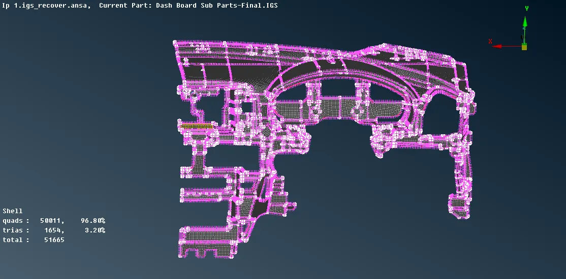
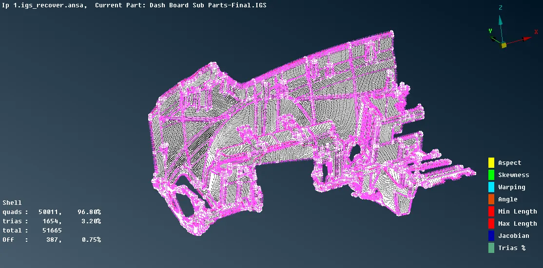
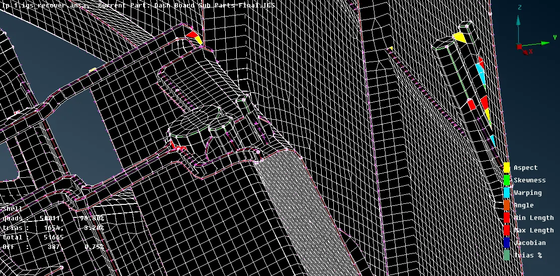
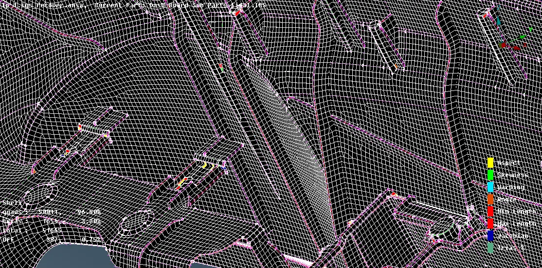
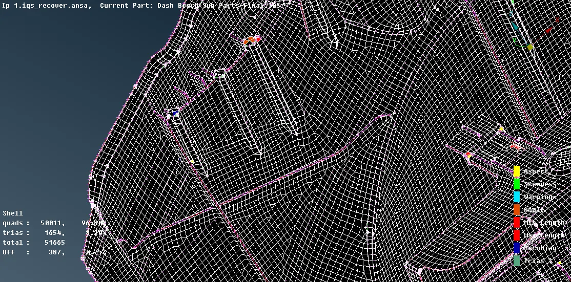
Conclusion:-
So by completing this challenge I learnt how to extract mid surface of the instrument panel component having varying features like ribs and locators and join them by intersecting or extending the surface and also how to mesh according to given quality criteria, after that how to perform the quality check and resolve rotating quad and trias for better mesh flow and also finally how to assign thickness.