SHELL MESH AND MID SURFACE EXTRACTION ON INSTRUMENTAL PANNEL
AIM:-To extract mid surface and mesh instrument pannel with satisfying quality criteria.
THEORY:-
As the component is the instrumental pannel which is majorly used in automobiles. Majorly it is called a dashboard in normal terms, where all components like instrumental cluster, A.C, vents clove box, sound box, etc.
AS now these are made of plastic to reduce the cost, increase safety, increase the effectiveness in design with less manufacturing cost.
PROCEDURE:-
- First, we need to topo the entire model.
- Then we need to check the geometry and keep the errors away from the model.
- Then we need to change the length of macros and perimeter then we need to observe the geometry is correct or distracted.
- After making all the corrections we need to extract the mid surface of the component.
- Then we need to defeature element which is failing for quality.
- Then we need to mesh the entire component to make sure to reduce the off in quality criteria.
GEOMETRY CLEANUP:-
-
We need to import the model from drive to ansa by using
File →open → select file → ok
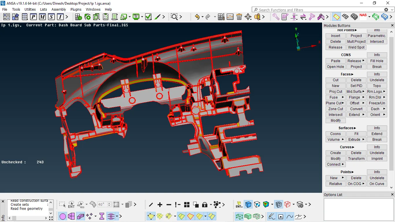
Fig:- model imported to ansa
- we need to perform topo to entire which will stitch the need node and from one surface
topo module → faces → topo → select model → enter/middle mouse click
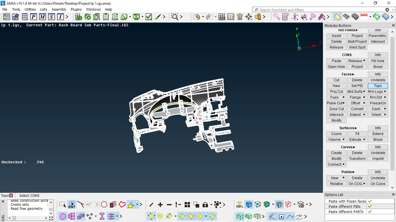
Fig 2:- performing topo
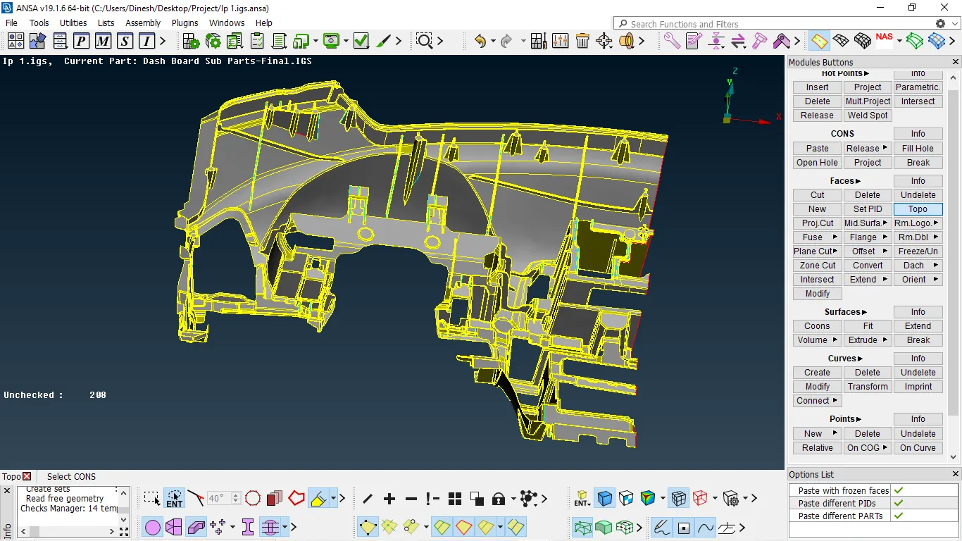
Fig 3:- After performing topo
- After performing topo the lot of triple cons that are wrong we clean up by using geometry checks.
- Then after check the geometry by using the geometry checks option in the tool
- Select all entities and the press execute, then it might show some errors
- Se must clean up those errors by using auto fix or manually
tools/toolbar → checks → geometry → all entities → execute
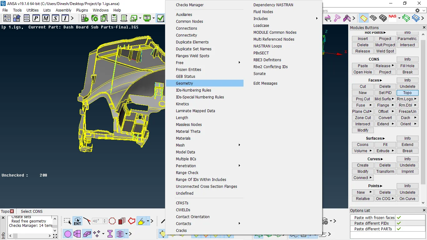
Fig 4:- Going to check geometry
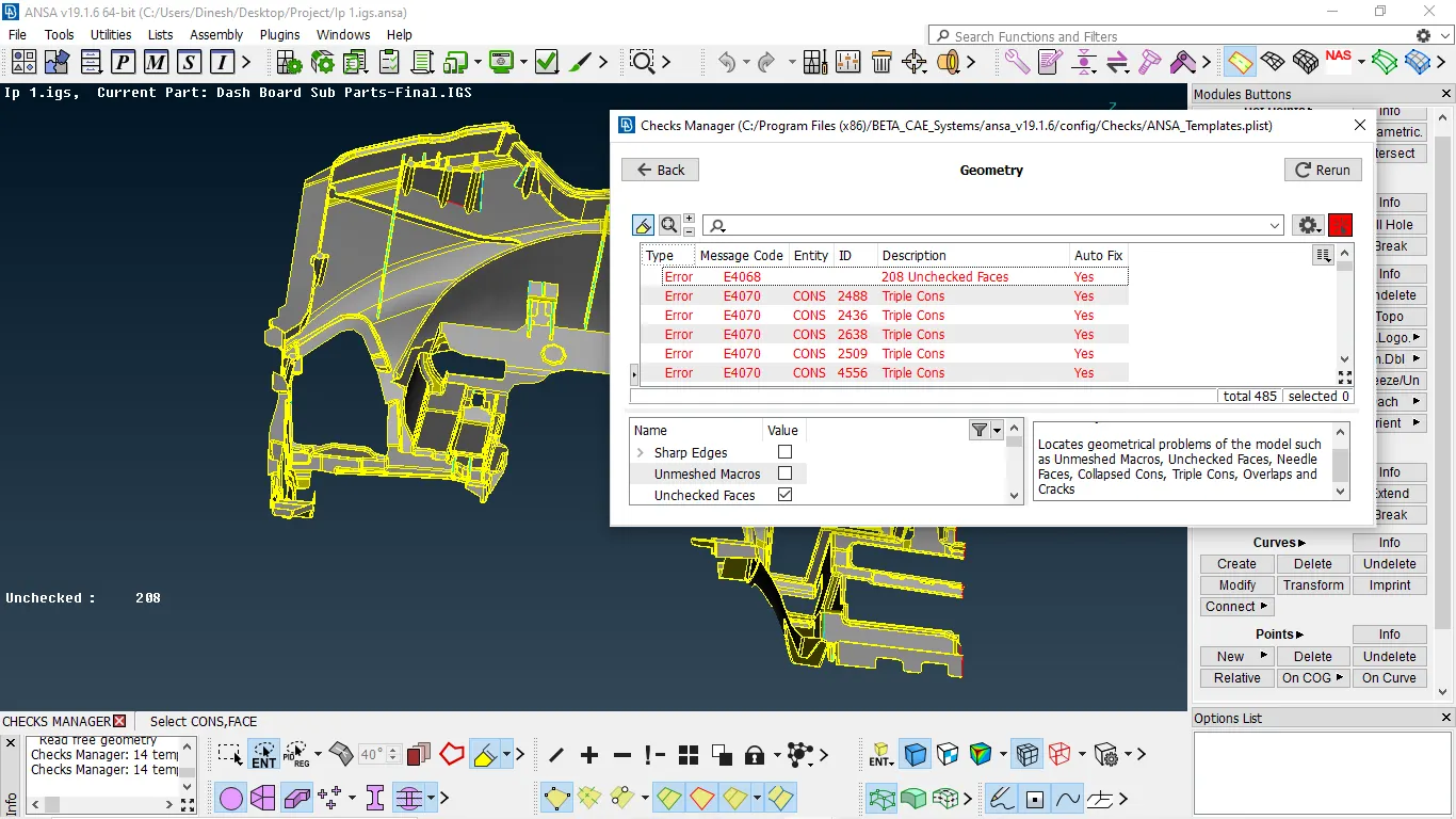
Fig 5:- Errors occurred after geometry cheks
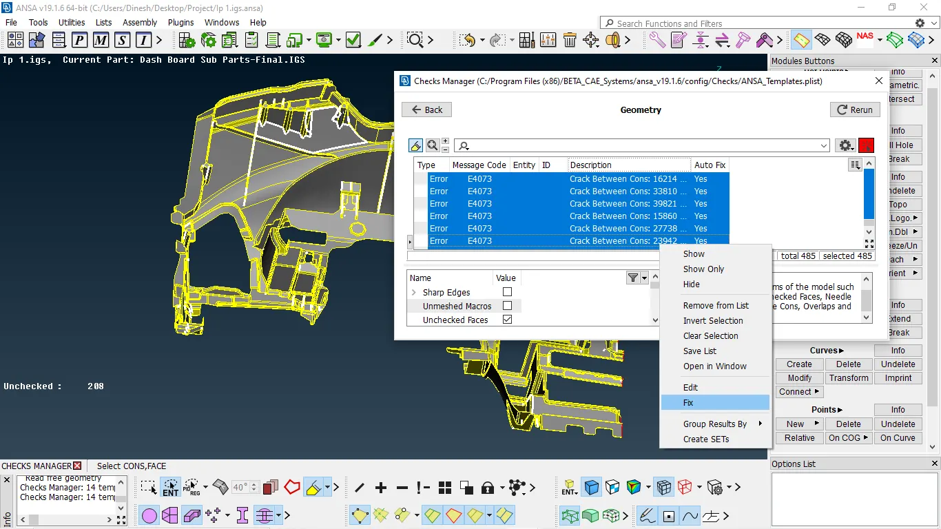
Fig 6:- Fixing errors automatically
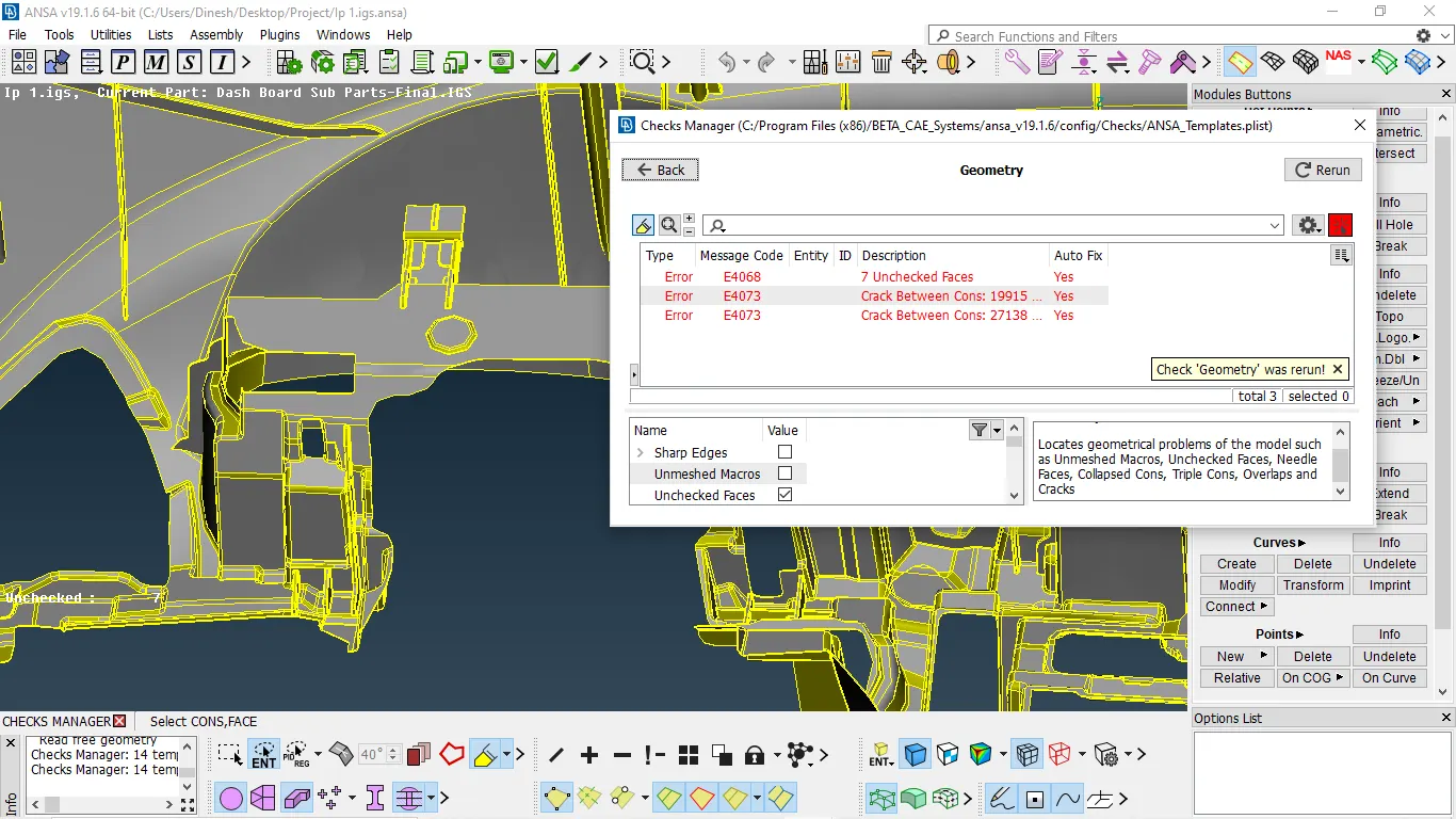
Fig 7:- Errors occurred after performing the auto fix
- We need to fix it manually
- By selecting them all make them show only after that we need to fix errors
- First, we need to fix the cracks
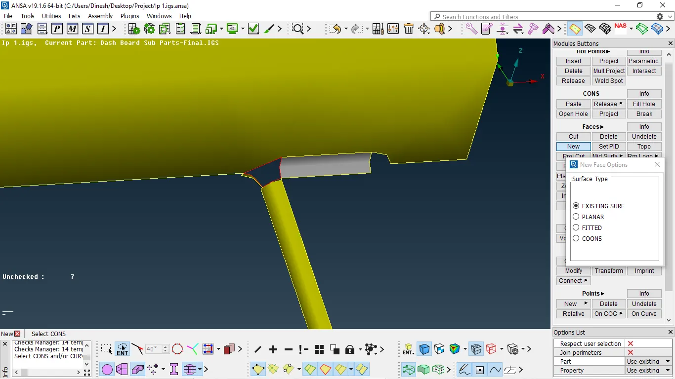
FIg 8:- Crack occurred in the component
- There are two options to fix the cracks by using paste or forming new faces.
- In this, we cannot do paste because the lost surface is larger than the tolerance.
- So, we need to form new faces
Faces → new → use planar/fitted/coons depends upon satisfying the feature with neighbors
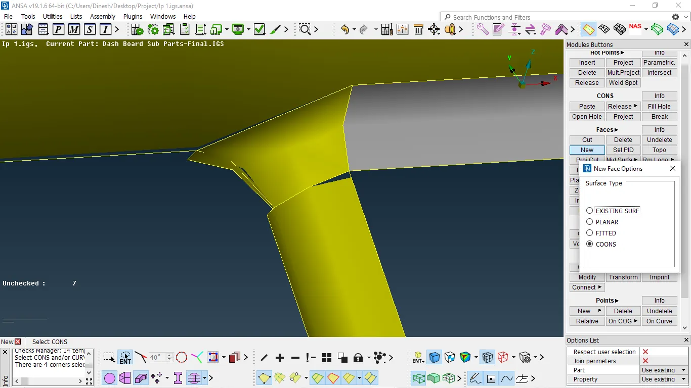
Fig 9:- After filling surface at a crack area
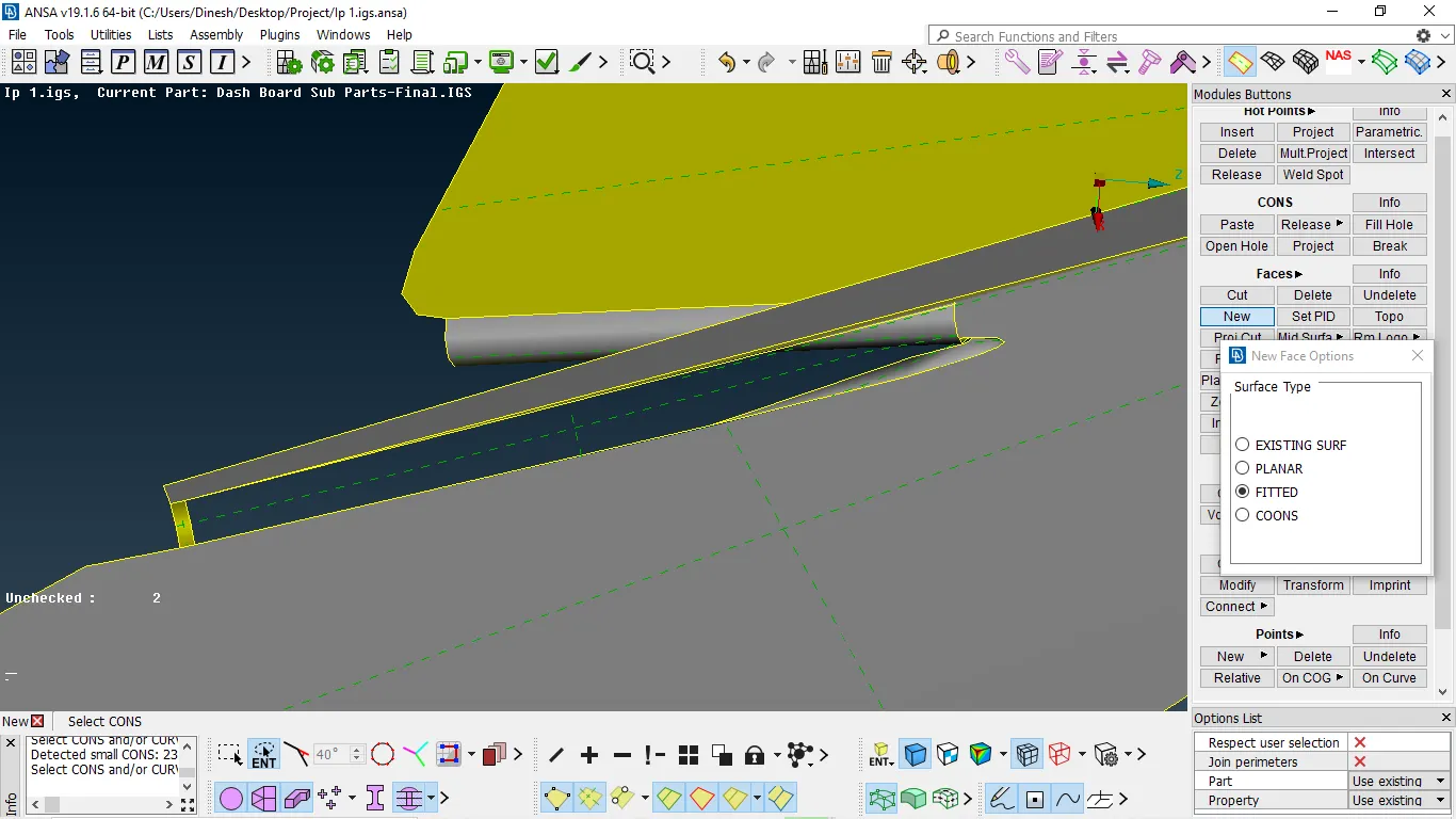
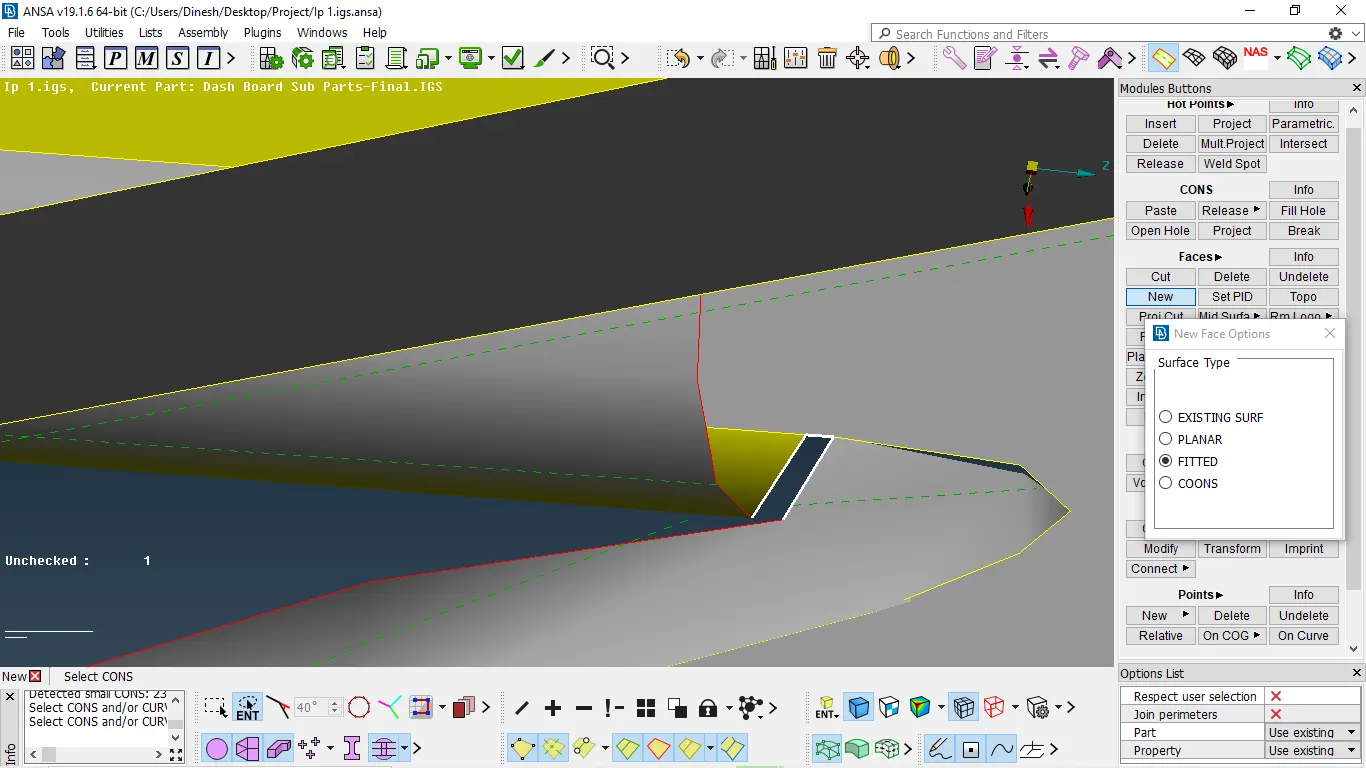
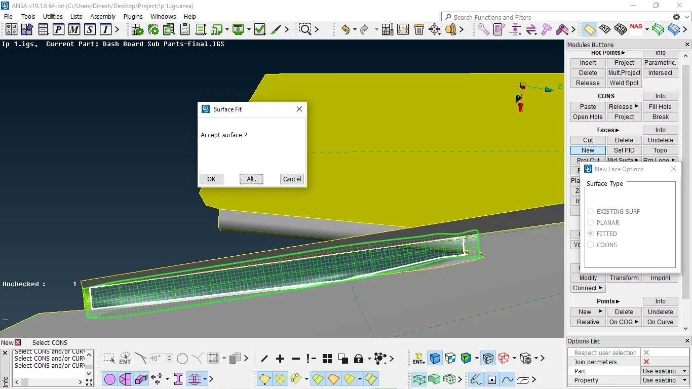
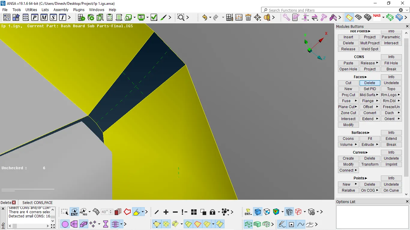
- As there are unchecked faces occurred in geometry
- Unchecked faces occur due to irregular geometry and unnecessary hot points
- If unchecked faces occurred then we need to release the cons and delete the hot points
- If unchecked faces occur due to irregular geometry we need to fix it by delete and forming new faces
TO delete face
Faces → delete → select the face → enter
TO FORM FACE
Faces → new → use planar/fitted/coons depends upon satisfying the feature with neighbors
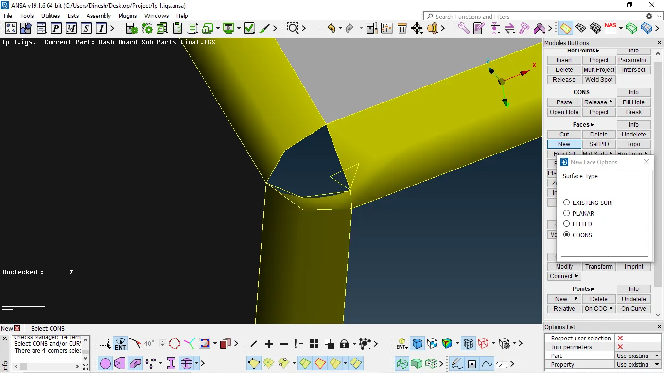
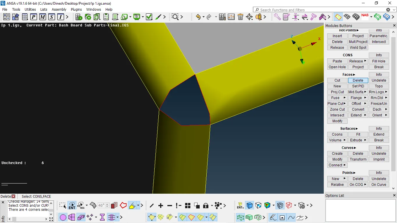
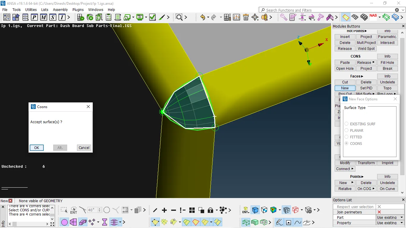
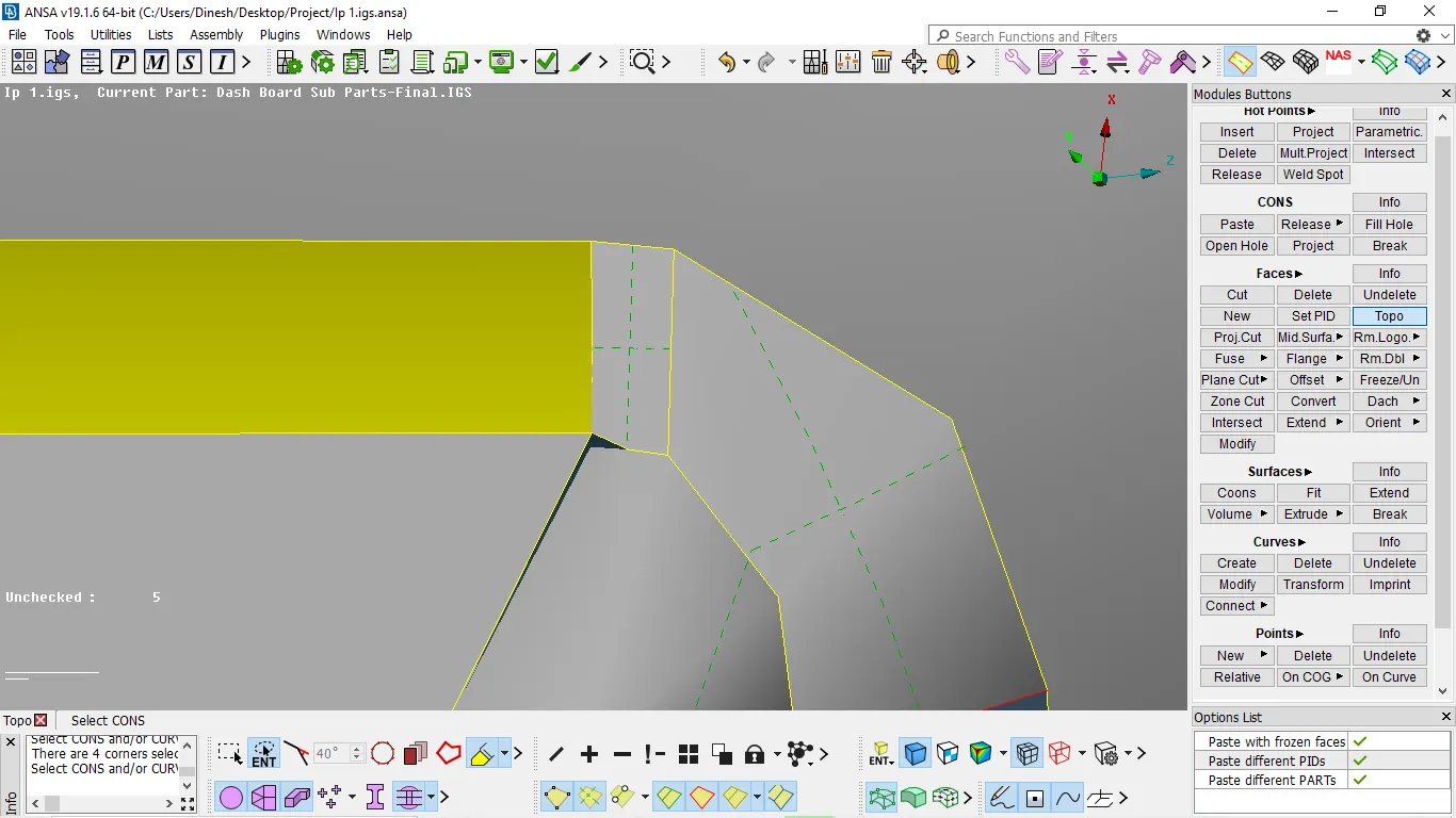
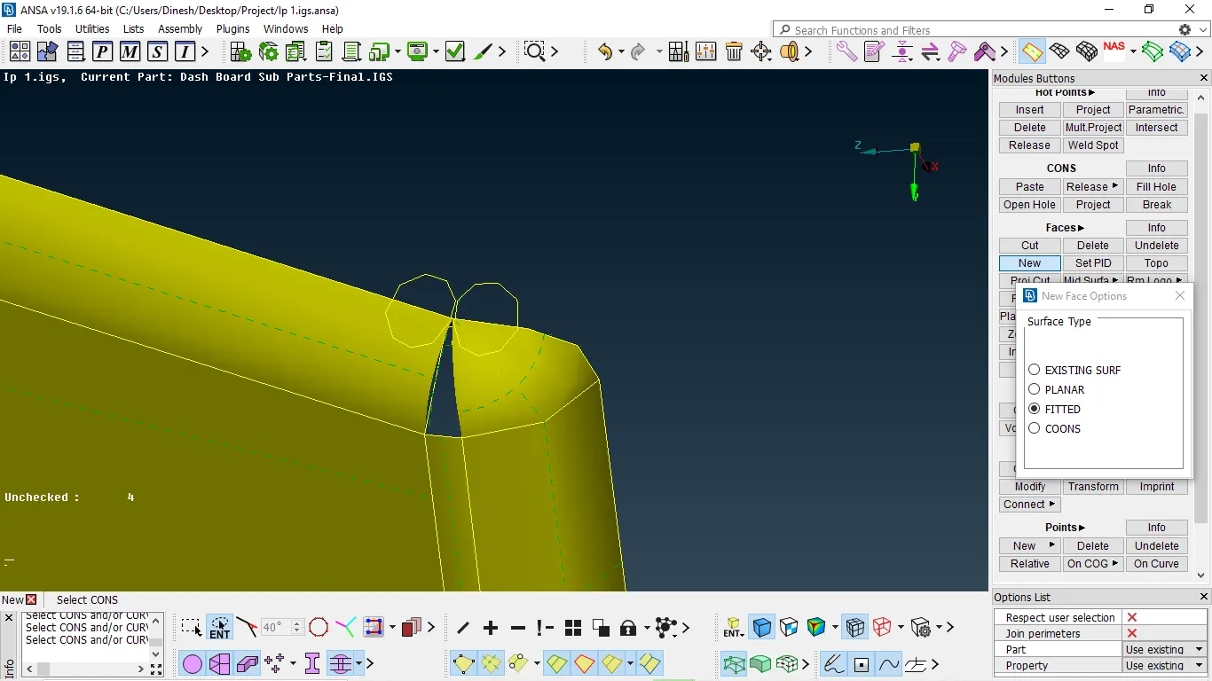
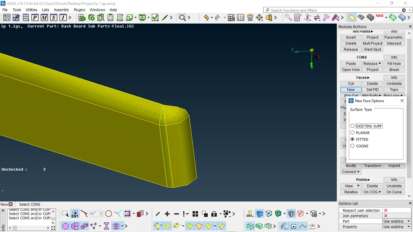
NOTE:- we need to form geometry with equal to the opposite node otherwise the geometry will be irregular.
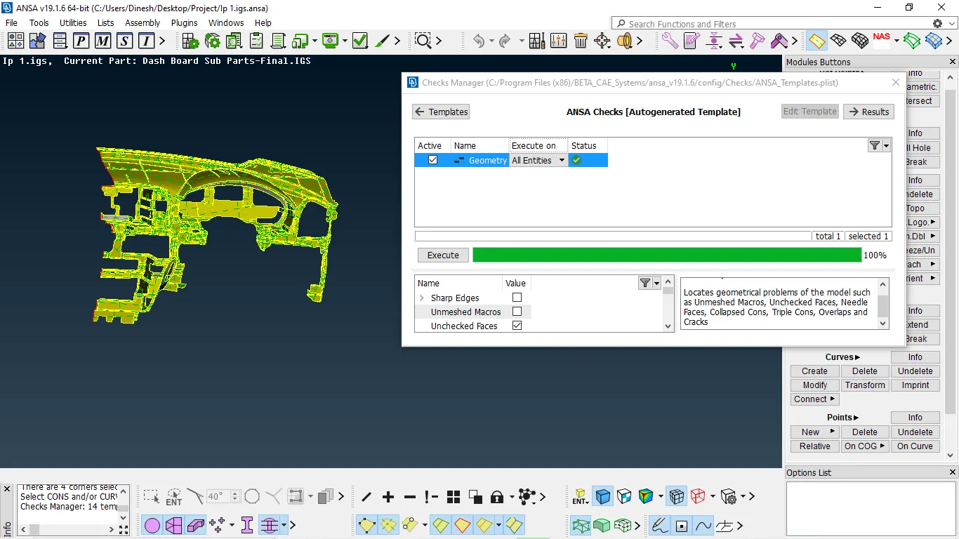
- Geometry cleanup is finished and then check geometry whether they fixed or not
- If fixed we continue further.
MID SURFACE EXTRACTION
There are many ways to extract mid-surface some of them are by using middle, offset in faces, and middle curve for complex shapes
- We use offset for surface majorly flat and having constant thickness
OFFSET THE SURFACE
- Measure the thickness → then select offset in faces → select the faces to be offset → give the value of the thickness → middle mouse
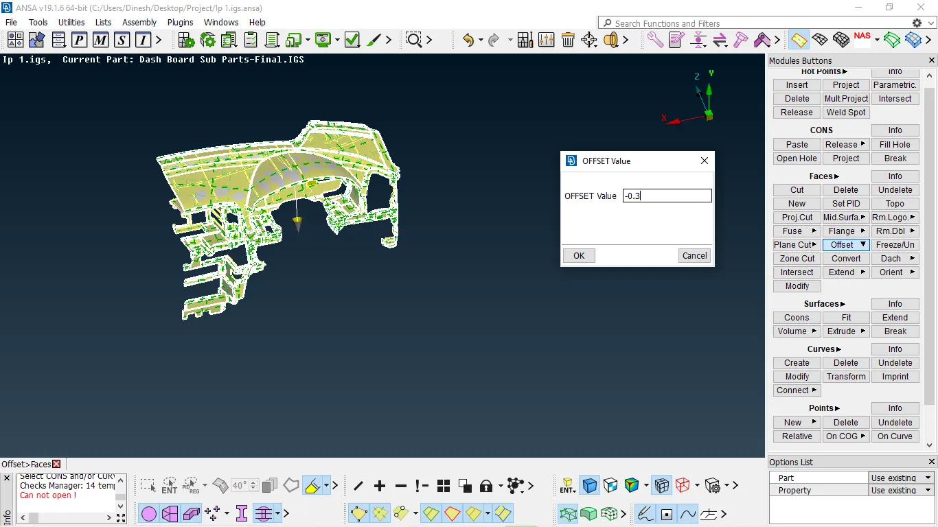
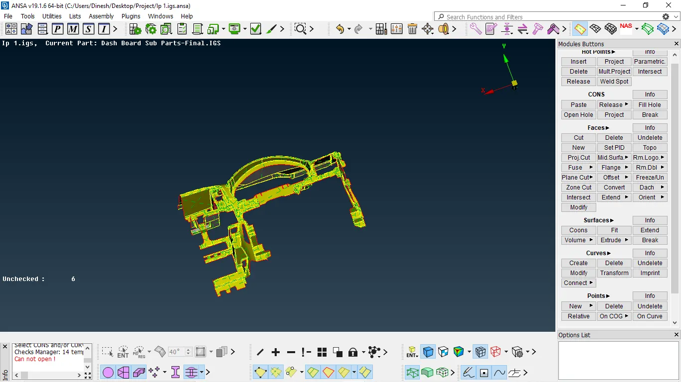
NOTE:- Unchecked faces in the mid surface are removed as same steps above
2.This method is used for symmetrical variable thickness parts and symmetrical parts also
face → middle → select two symmetrical surfaces it automatically produces mid surfaces → press yes
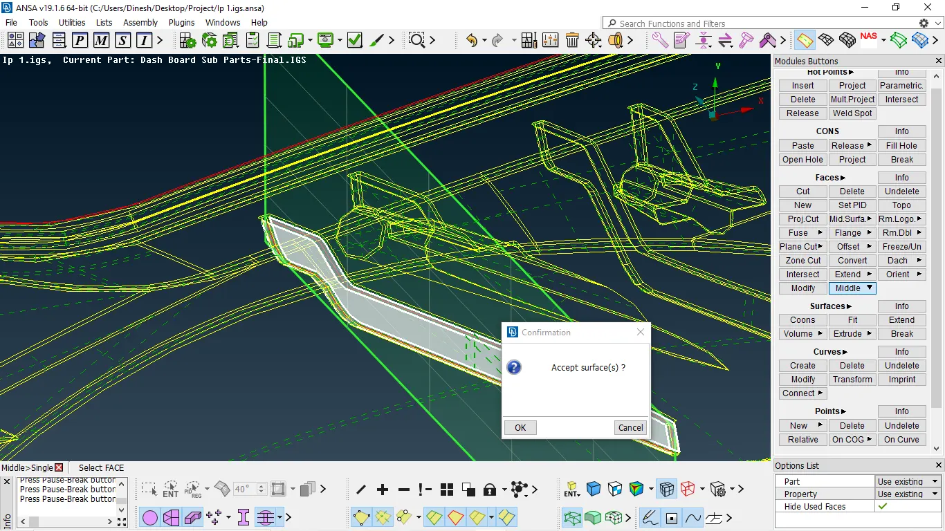
Fig 1:- extraction of middle surface for ribs
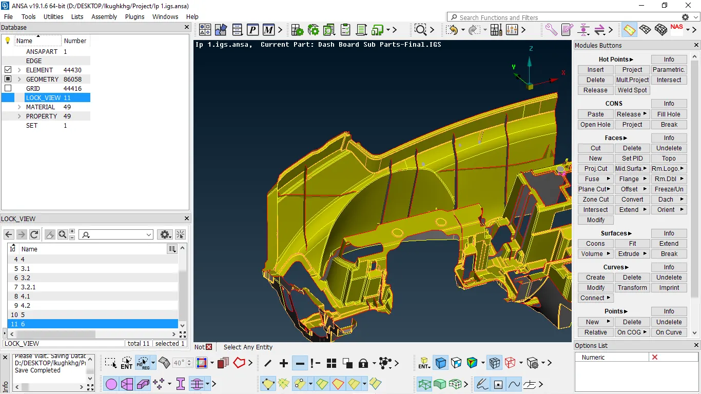
Fig 2:- Mid surface extracted for all ribs by middle option
MIDDLE FOR MOUNTING POINTS
- As the mounting points are solid we need to make some assumption to capture them
- To capture the middle surface for them we need offset to 0.5mm and keep the thickness as 1 in the property ID
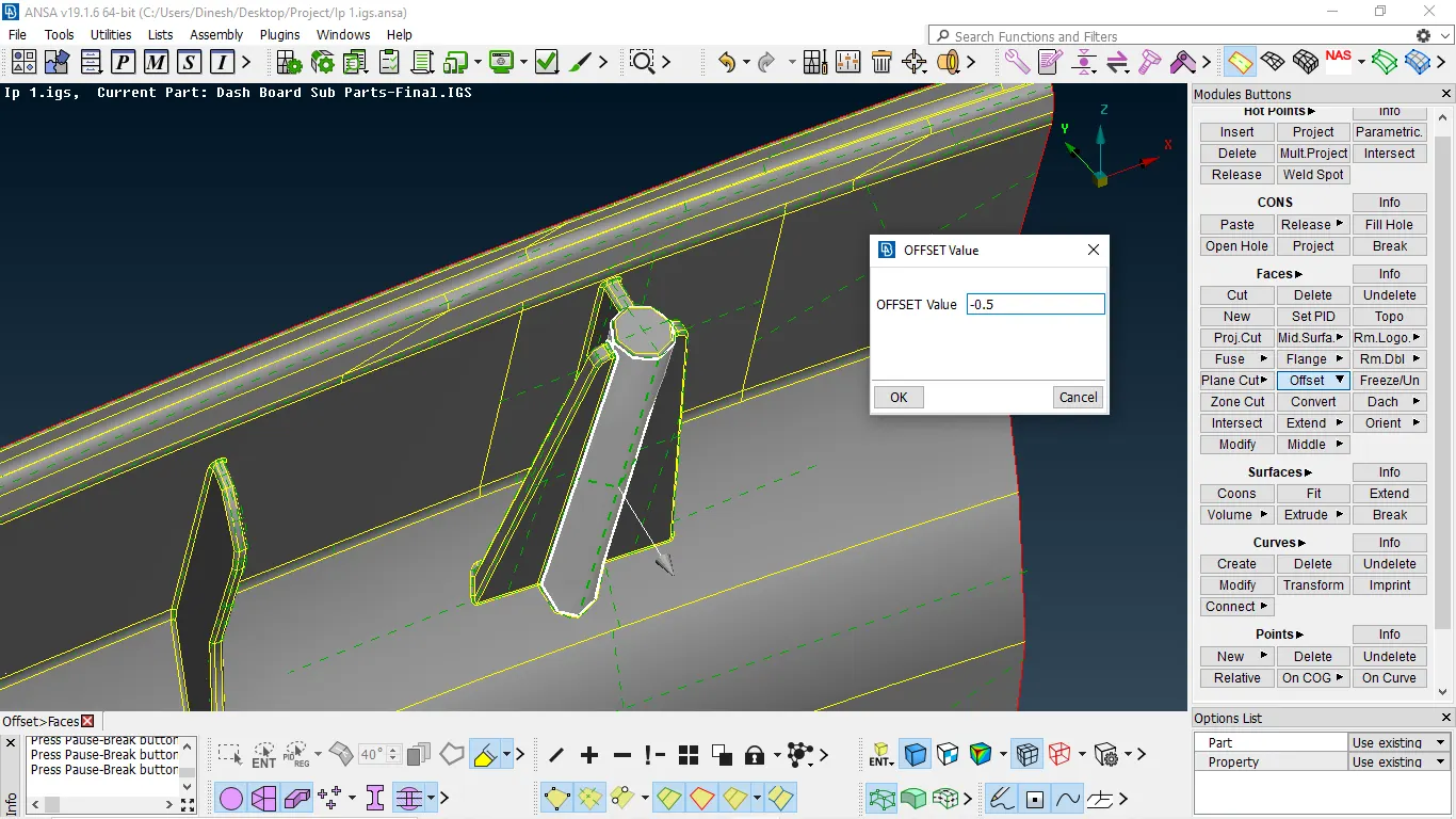
Fig 3:- offsetting the mount to 0.5mm
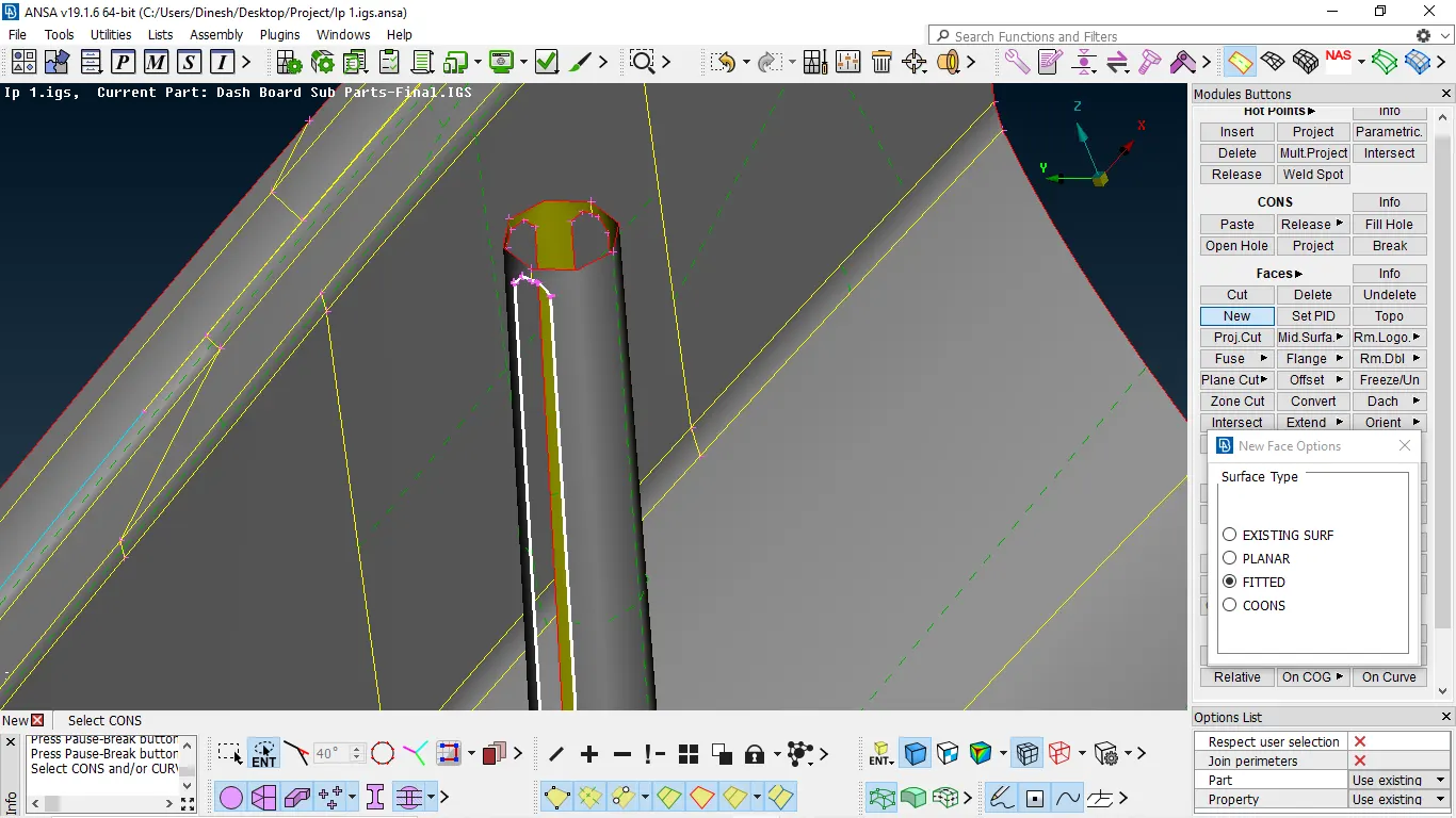
Fig 4:- Due to offset irregularities we need to patch it up with new faces
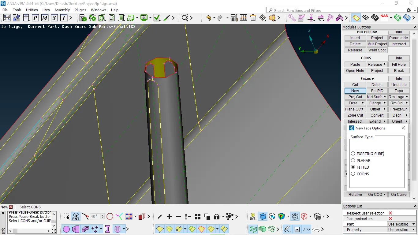
Fig 5:- patching of offset surface is done
- As the parent surface of the mount is connected to the surface we need to extend the mid surfaces
we need to connect with each other faces → select the surface to be extended → and select the surface to limit → enter
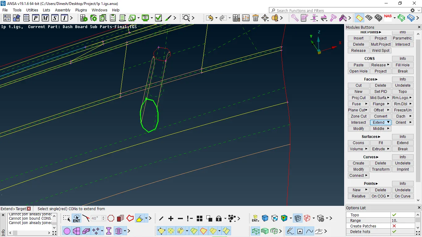
Fig 6:-surface selection to be extended
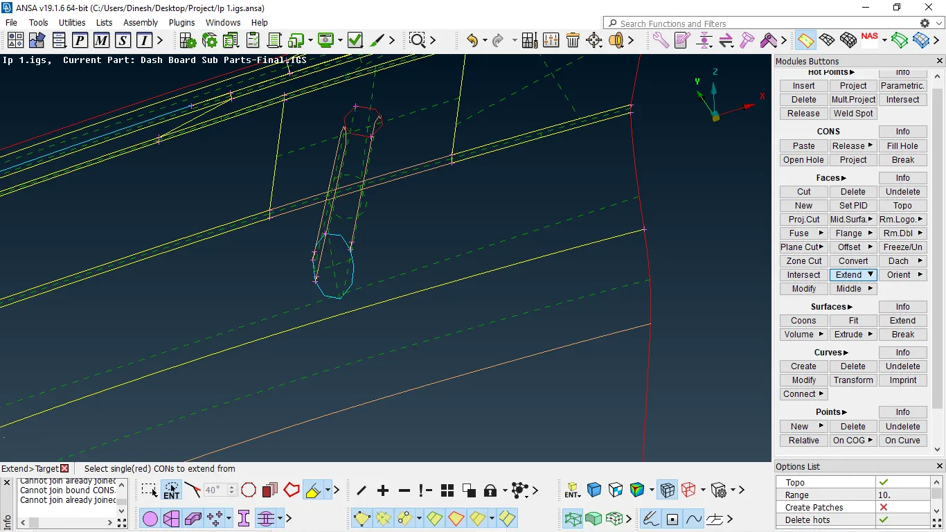
Fig 7:- Surface extended
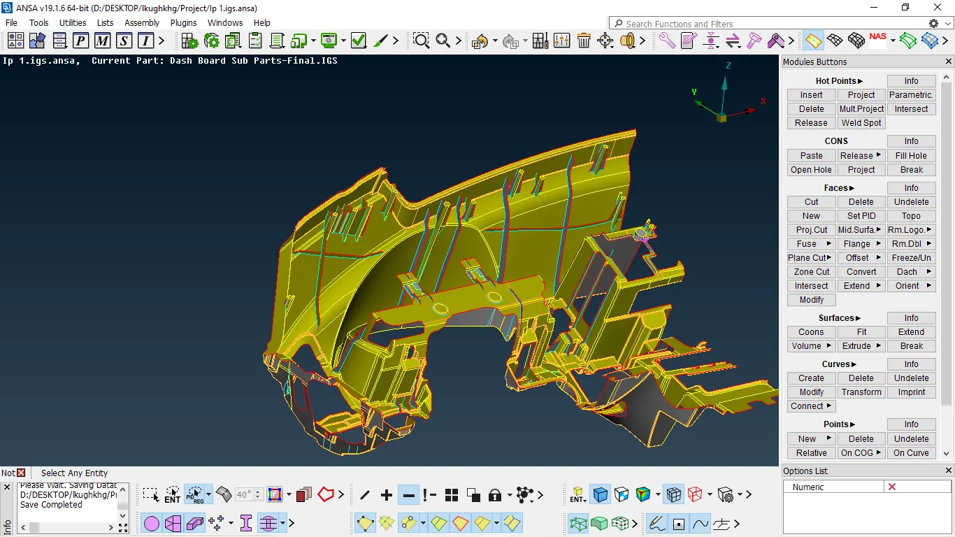
- mid surface extracted and extended to the surface
DEFEATURING:-
- Defeaturing is a part of meshing
- Defeaturing is done to satisfy mesh with respect to quality criteria
- The fillet which is less than min element length must be defeatured
- There are two methods to defeature one is dach and the other is divide faces
- Dach will delete the fillet and form a sharp edge
- Divide face will capture the feature perfectly without any deviation
- Majorly we divide faces to capture the area
- It is recommended to divide the component into different parts it will help to defeature and mesh them easily
Topo module → faces → dach → divided face → select the face → join macros → enter
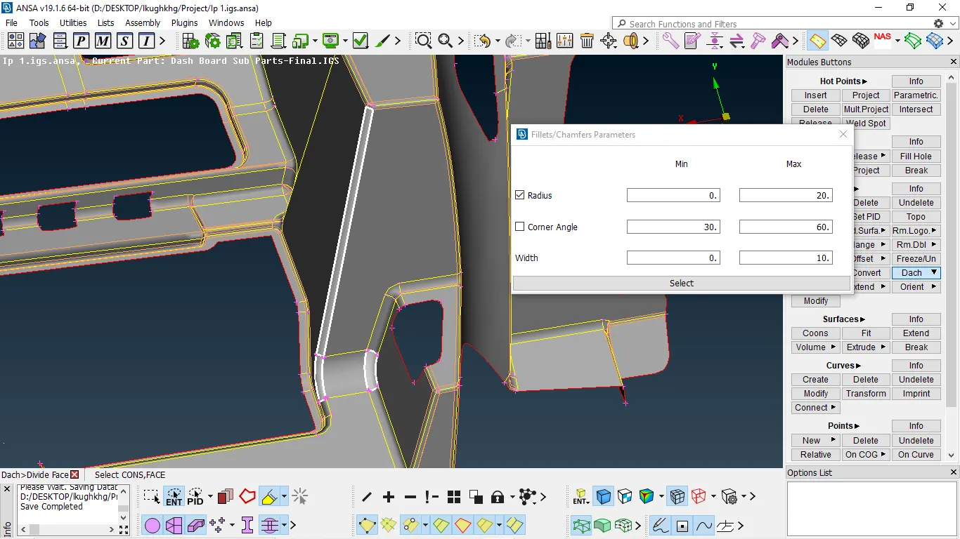
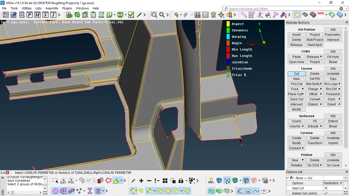
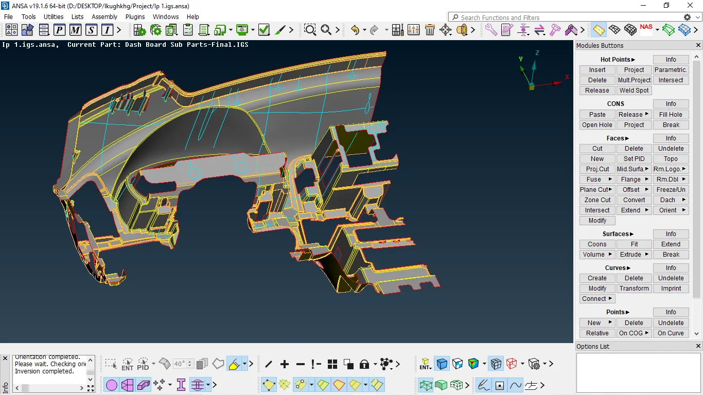
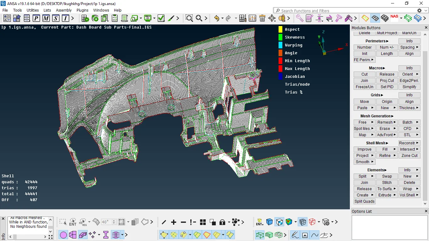
- Defeaturing for the entire component
MESHING:-
- Before meshing we should complete geometry checks for all
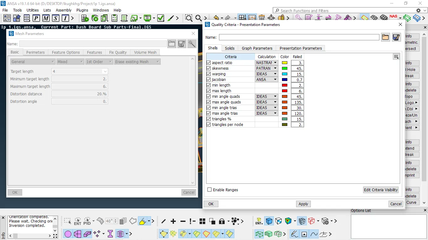
- Assign mesh parameter and quality parameters
utilities → quality parameters/mesh parameters → enter value → ok
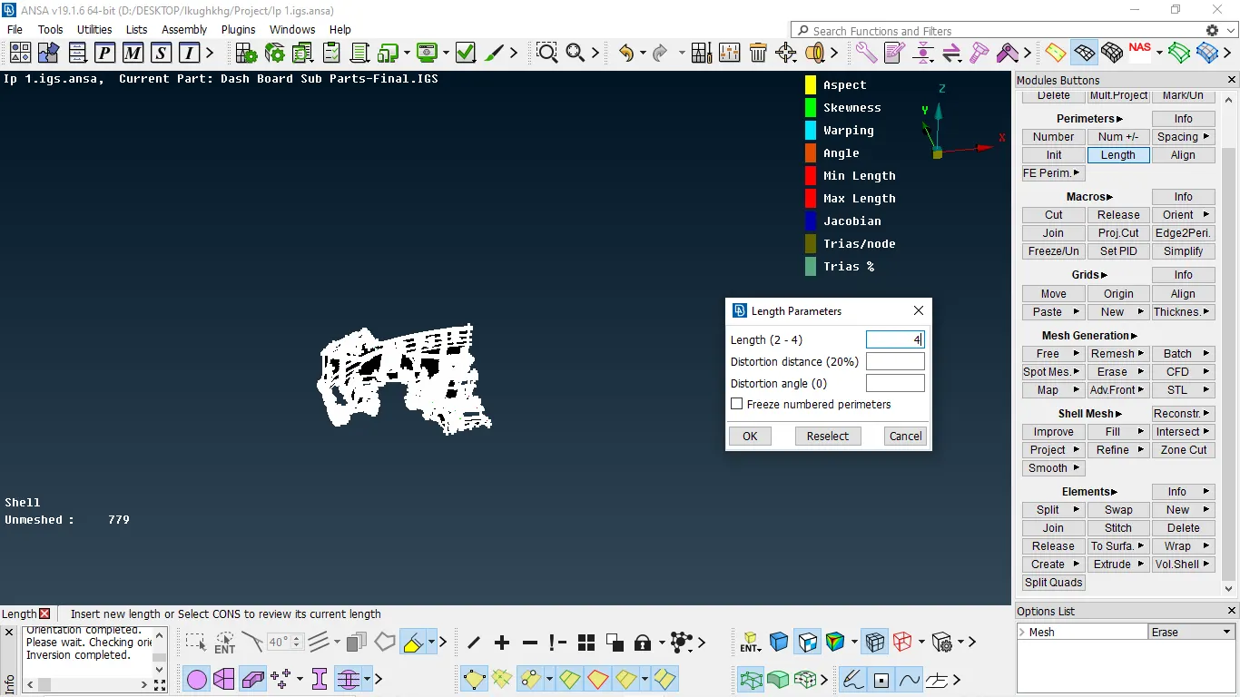
3. After that, we need to give perimeter and macro length
mesh module → perimeter → length → select the surface → select perimeter /macros → enter the value → enter
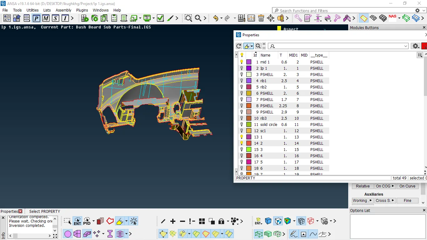
4.Before starting meshing we need set the component to different PID and we must assign thickness
5. After completing we can start meshing, select the surface and start meshing
mesh generation → Spot mesh → select surface and enter
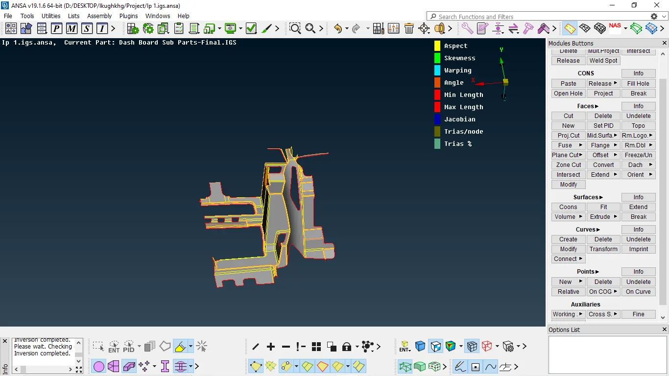
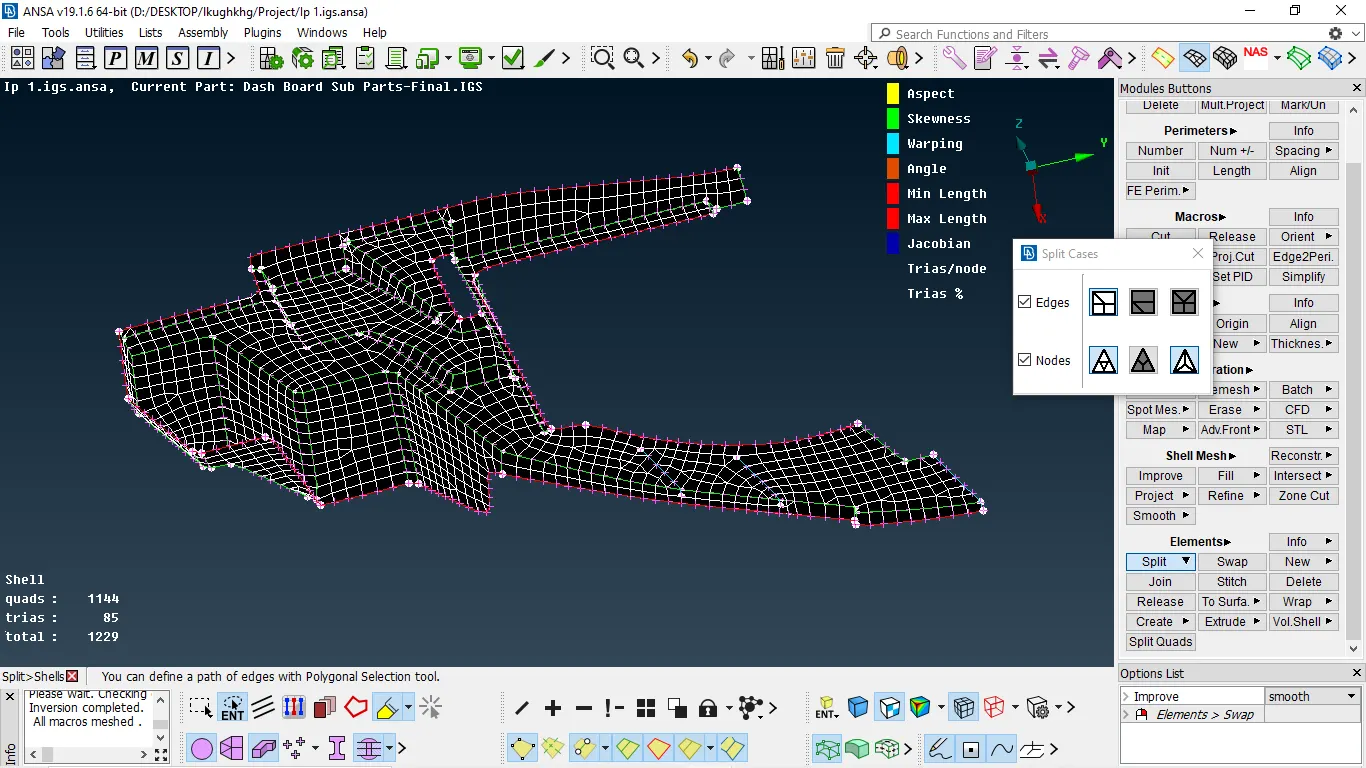
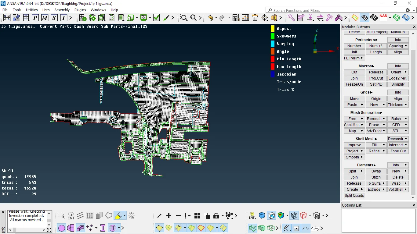
Fig 1:- subpart without meshing
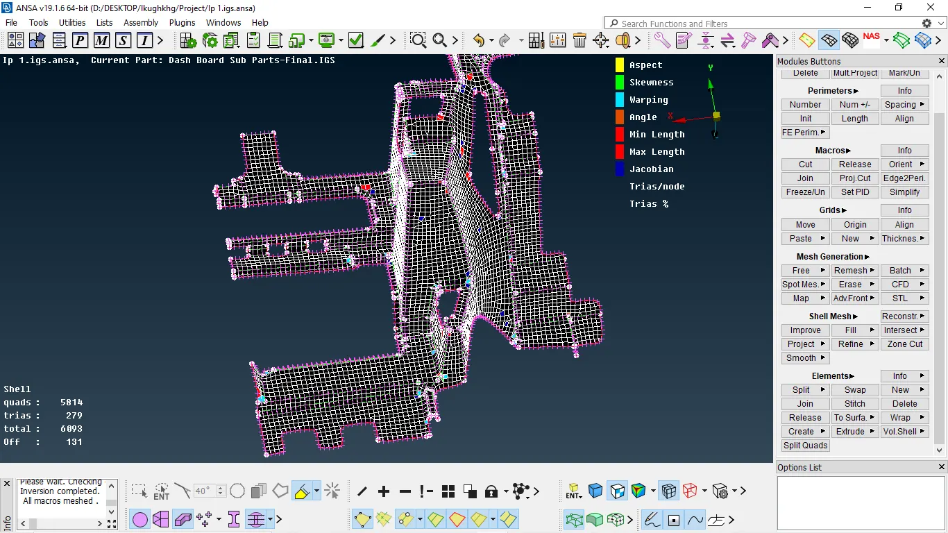
Fig 2:- subpart after applying spot mesh
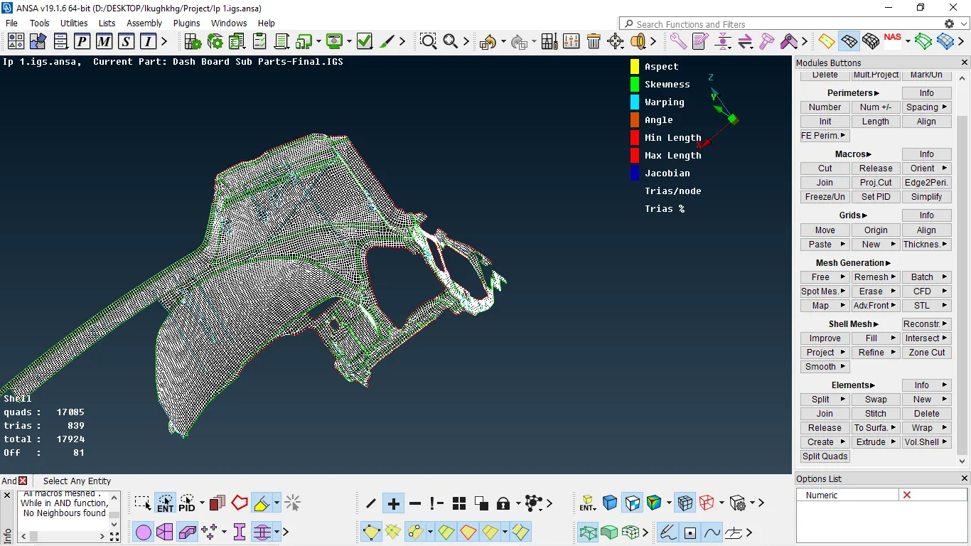
- Reconstruction is done by using mesh reconstruct and smooth we can reduce the off elements
- BY using split and swap we can reduce the concentration of trias and decrease the stress concentration areas
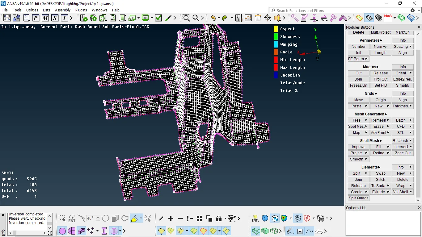
Fig 3:- subpart after reconstruction of mesh
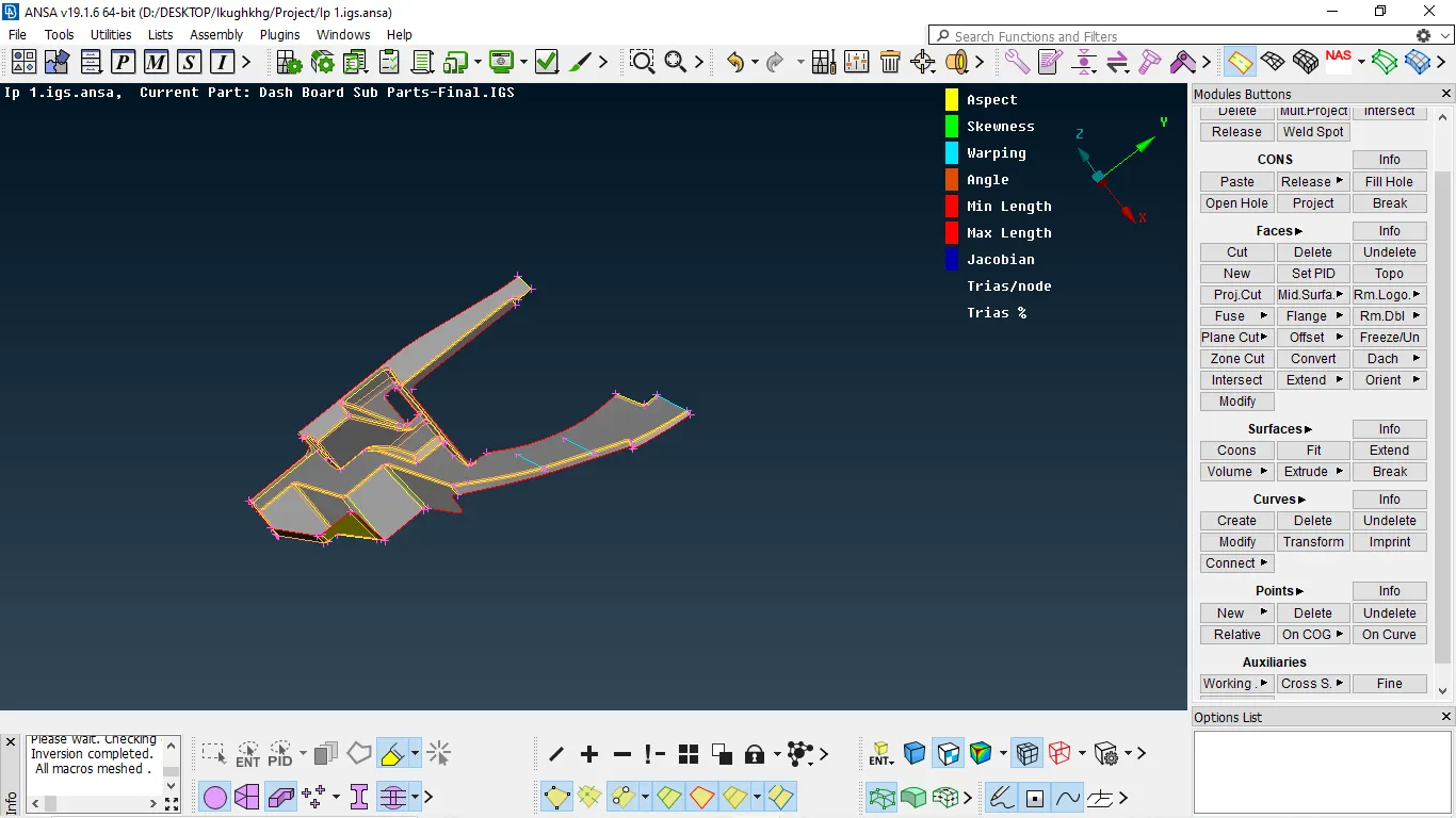
CONCLUSION:-
- Understood how to extract the mid surface at complex areas
- understood how to mesh large component
- understood how to reduce the quality error in mesh
- understood the extension and attachment of the mount to parent surface
- understood how to capture feature by satisfying quality criteria
- understood how to perform divide faces to defeature the fillet area