Project 1 - 2D meshing on the instrumental Panel
AIM:
Pre-processing of the car instrument panel using ANSA
OBJECTIVES:-
- Introduction to shell meshing or 2 D meshing.
- Topological errors and geometry errors clean-up.
- Extracting mid surface with a different method.
- Meshing the geometry within quality parameters.
- Rectifying quality errors i.e. solving off elements.
- Improving mesh flow pattern.
QUALITY CRITERIA:
|
S.No |
Quality Criteria |
Value |
|
1 |
Target/Average length |
4 |
|
2 |
Minimum Length |
2 |
|
3 |
Maximum Length |
6 |
|
4 |
Aspect |
3 |
|
5 |
Warpage |
15 |
|
6 |
Skewness |
45 |
|
7 |
Jacobian |
0.7 |
|
8 |
Minimum Quad Angle |
45 |
|
9 |
Maximum Quad Angle |
135 |
|
10 |
Minimum Tria Angle |
30 |
|
11 |
Maximum Tria Angle |
120 |
|
10 |
Tria Percentage |
15 |
INSTRUMENT PANEL:
Introduction:-
The instrument panel is a control panel for the driver of the vehicle which is situated ahead of the driver's seat. The instrument panel includes a speedometer, fuel gauge, airbags, steering columns, media control panel, glove box bean, air ducts, side indicators, seatbelt warning, GPS navigator, mobile holder, etc. As the largest inner trim part directly shown to the passenger, the instrument panel has not only beauty and function required but also NVH and safety requests. The vibration and the noise on the dashboard can be directly felt by the passenger. Thus, the FEA analysis of the instrument panel plays a very important role in the whole vehicle's NVH character.
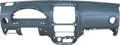
The substrate may be formed from a rigid material, such as metal or rigid plastic. The instrument panel doesn’t necessarily need to have heavyweight material to keep the part intact, rather it can be done using the part that is lighter, save costs. But we need to make sure that the material is rigid and design good enough so the material does not fail in NVH test.
GEOMETRY CLEANUP:
After importing of cad model into ANSA, there will be many geometry errors present in the model. we have to check and clean them before meshing them.
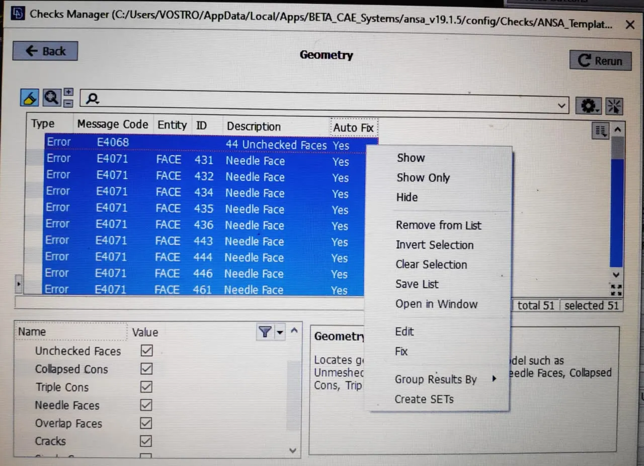
The checks manager will check the geometry and show the errors which are in the cad model. The required feature such as unchecked faces, triple cons, needle faces, cracks, collapsed cons has to be kept on so that checks manager will show the errors based on the feature as selected. There are two options for cleaning these geometry errors. These errors can be cleaned one by one approaching the error area and fixing the error by deleting cons and hotpoints. The other method is that fix the errors by ANSA itself by using the fix option in the checks manager. This method is the most preferred one because it reduces time consumption.
MIDSURFACE EXTRACTION:
The mid surface can be extracted by two methods 1) Manual method and 2) Auto mid surface method.
1] Manual method:
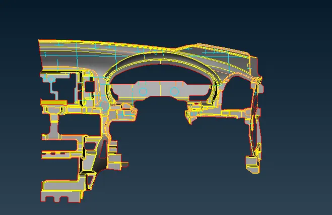
In the manual method we use Topo> Faces > offset option for extracting mid. The manual method is time-consuming but extracted mid is accurate as compared to the auto mid method, therefore I go for a manual method for extracting mid-surface. For a surface containing complicated features first select the less surface feature and offset it at mid as shown in below image 3.1 After creating mid surface assign PID and thickness to it. In the manual method, ANSA always asks to delete parent geometry or not, while in the auto mid surface method parent geometry is deleted without asking the user.
2] Auto mid surface generation :
This method can be done by selecting the mid surface option under the face module, select the skin option and select the full geometry, and confirm the mid location. this method can only be used when the model is closed. Midsurface for a component has been generated by using an auto midplane option. the parent surface will be deleted while using the auto midplane option. likewise, midplane can be extracted for other geometry by using an auto or manual midplane method. after creating a midplane for all the geometry we have to create a property id for each geometry.
- Generation of mid surface for the upper cover of the instrument panel :
Here, a thickness of 0.6 mm is uniform across the upper cover of the instrument panel so I used TOPO > Offset option and select value 0.6/2 mm for getting mid surface at the middle. while selecting the area I select the feature option so that whole area is captured in one shot. While selecting an area for the offset option always select the area which are having fewer features.
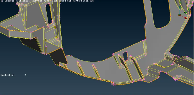
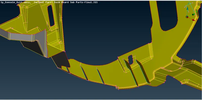
2.Ribs are an important feature that provides strength to the structure. In the substrate, there are various places, where there are ribs. The ribs depending on the location have a different design as well as varying thickness. The ribs connected to dog pins are used for support purposes. Here too, the ribs have varying thickness depending on the location. Some of them are in the following
Before mid surface
After mid surface
The above ribs have a thickness of 2 mm. So, we will have the mid-surface at 1 mm.
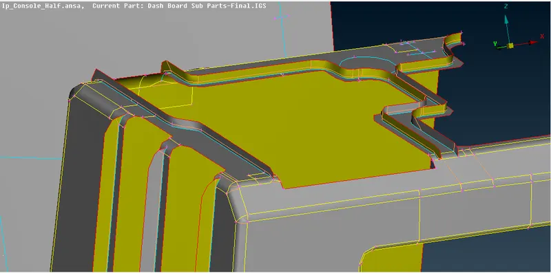
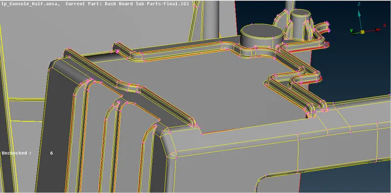
After mid surface Before mid surface
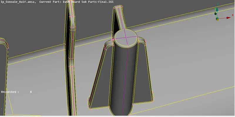
- Mid surface generation for dog houses
For generating the mid surface of dog houses, Dog houses in this model captured as "Cross pattern" in Mid surface since dog houses are solid and are not having any thickness. I used the Curves -> Middle option and then I created a surface using curves and extended it to the surface.
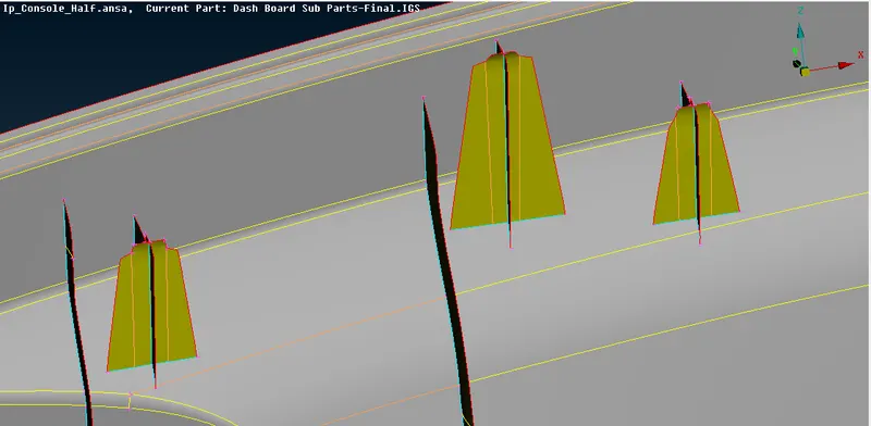
After mid surface Before mid surface
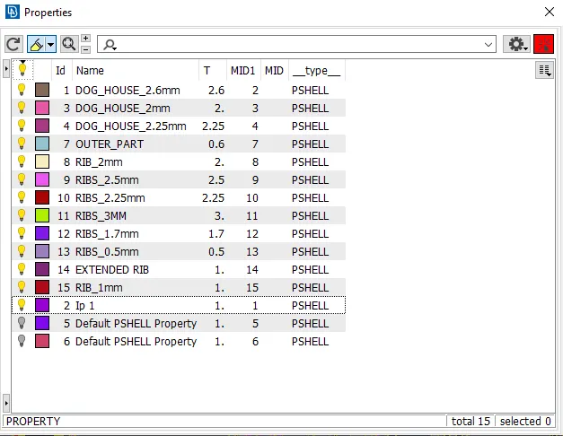
We need to make sure that the PID of all parts is set before we begin meshing. Property id can create by selecting the SET PID option under the face module button.
QUALITY CRITERIA SETUP:
We must assign quality parameters such that meshing elements will get measured from their ideal shape. The parameters like warping, skewness, aspect ratio, etc.. have to be given in the quality criteria setup. meshing parameters also have to give before meshing such that surface will get mesh under given length.
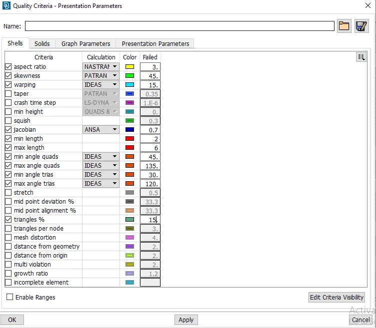
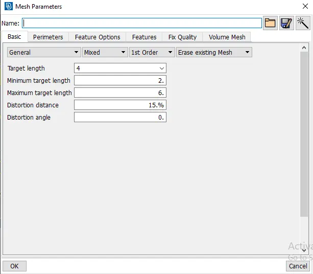
Quality criteria Mesh parameters
DEFEATURING:
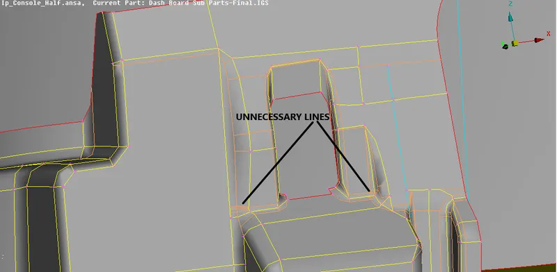
Defeaturing means removing unnecessary construction lines and curves in the CAD model because of manufacturing constraints. we have to remove them or arrange them properly for a better mesh flow without failing quality criteria. Very small entities can be a problem if you have a very small face with sharp angles, meshing might get fail. Therefore check the CAD model for very small entities and remove them before creating a mesh for it.
MESHING:
Meshing is an integral part of the engineering simulation process where complex geometries are divided into simple elements that can be used as discrete local approximations of the larger domain. It is a network that is formed of cells and points.
Now we can finally mesh the component after defeaturing the complex areas. there must be better mesh flow in the component. Before starting meshing we have to set the perimeter elemental value as 4mm so that perimeter points will be arranged within the limit in the surface edges.
Most of the quality issues will be seen in the areas of ribs and features. We will Reconstruct the Macroregion or rearrange the construction line in such areas. The other areas where there will be quality issues will be the area where triple cons intersect, or triple cons are present near the double cons.
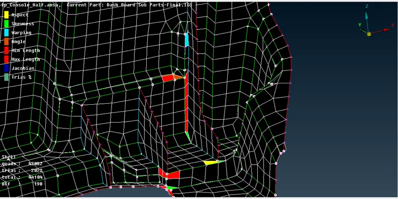
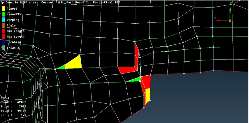
There are many areas where the quality errors cannot be removed due to the minimum length or geometric constraints, those are the region we will leave and proceed with the mesh correction step. The step involves removing the opposite trias or removing the trias element from the perimeter as much as possible. Another trias element that needs addressing is back-to-back trias, but we will remove the one which is possible to remove because the errors such as jacobian or skewness in many areas are removed by splitting the element in two. In such areas, the back-to-back trias will remain. We will try to refine the mesh to get a better mesh result.
RESULTS:
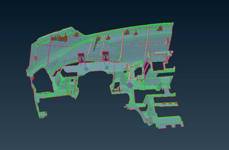
AFTER MESHING:
CONCLUSION:
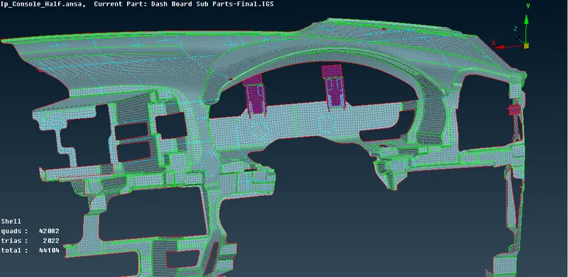
The panel had been captured quite a well-using shell mesh. The total element 44104 out of which 2022 are Tria element and 42082 are Quads which makes 4.58% which is a decent percentage of Tria element. . Most of the areas of fillets are captured using dach options and defeaturing is done in areas where construction lines are too close. The mesh flow is smooth nearer to the target length of 4 mm and within the quality parameter.
LEARNING OUTCOMES:
- Geometry cleanup and performing topology
- Generating Midsurface
- Assigning quality criteria and mesh parameters
- Able to understand and implement good practices of meshing any complex geometries.