Project 1 - 2D meshing on the instrumental Panel
I'm uploading the google drive link for the model because the model size is too high it is not getting upload in the mentioned area. I have tried multiple times to load it in the specified area to upload the model but it is not happening.
Link for the model:
https://drive.google.com/file/d/1449UBTW34BmH7GGWlQP4M3UNnoQaIck_/view?usp=sharing
Objective:
For the given component, check for the geometrical errors and mesh with the given element Quality criteria. After meshing the component the thickness has to be assigned.
|
S.No |
Quality Criteria |
Value |
|
1 |
Target/Average length |
4 |
|
2 |
Minimum Length |
2 |
|
3 |
Maximum Length |
6 |
|
4 |
Aspect |
3 |
|
5 |
Warpage |
15 |
|
6 |
Skewness |
45 |
|
7 |
Jacobian |
0.7 |
|
8 |
Minimum Quad Angle |
45 |
|
9 |
Maximum Quad Angle |
135 |
|
10 |
Minimum Tria Angle |
30 |
|
11 |
Maximum Tria Angle |
120 |
|
10 |
Tria Percentage |
15 |
Procedure:
- Open the Ansa software and import the model into the software.
- After importing the model, check if there are any single cons present in the model. If any single cons are present in the model try to convert them to double cons by using the Topo command.
- Click on the Topo command present in the Faces tools which are indeed present in the Topo deck.
- After selecting the Topo command select the whole component and middle-click to confirm the conversion of single cons to double cons.
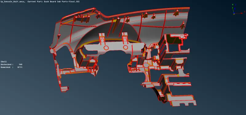
INSTRUMENT PANEL MODEL WITH SINGLE CONS ALL OVER THE SURFACES WHEN IMPORTED INTO THE SOFTWARE
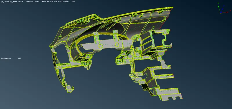
BY USING THE TOPO OPTION THE SINGLE CONS ARE CONVERTED TO DOUBLE CONS
- After converting the single cons to double cons, check for the geometrical errors in the component by using the Checks tool present in the Tools at the top of the menu bar.
- Click on the Checks command from the list of tools and select the Geometry option. After selecting the Geometry option a window will popup.
- In the pop-up window, there are several options to check for geometry. Firstly, in the Execute on options change from the model to the visible option.
- If we change it to visible all the visible geometry will be selected for the geometry checks.
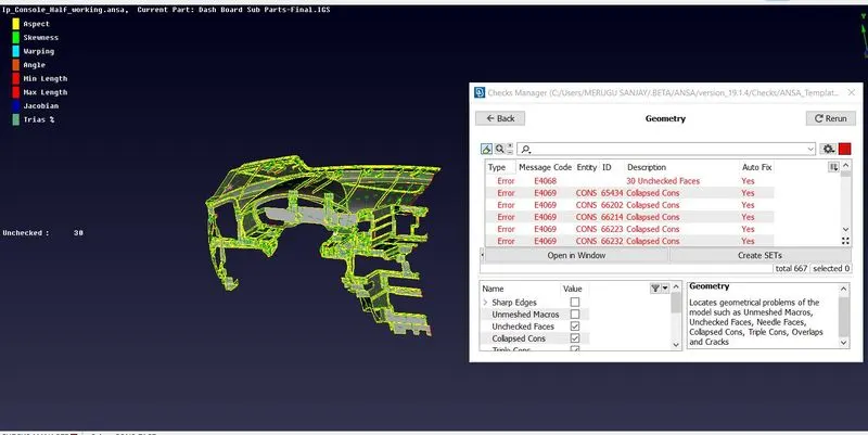
THE POPUP WINDOW SHOWS THERE ARE MANY GEOMETRICAL ERRORS
- The status shows if there are any geometrical errors and a list of errors will be shown. Clear the errors one by one manually by fixing them or automatically by selecting all the listed errors and right-click after selecting and click on the Fix command.
- After clearing all the errors, try to extract the midsurface for the given instrumental panel model.
- There are a lot of components on the given model like ribs, dog houses etc. The mid surfaces should be taken according to the specified conditions.
- After extracting all the mid surfaces from the parent geometry try to mesh the component.
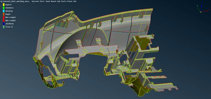
THE MID SURFACES HAVE BEEN EXTRACTED FROM THE PARENT GEOMETRY
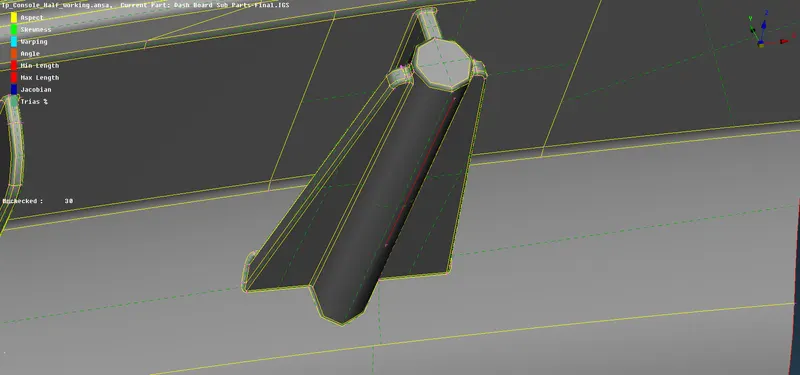
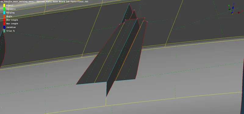
PARENT GEOMETRY FOR THE DOGHOUSE EXTRACTED MIDSURFACE OF THE DOGHOUSE UNDER SPECIFIED CONDITIONS
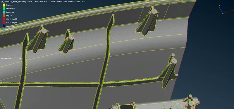
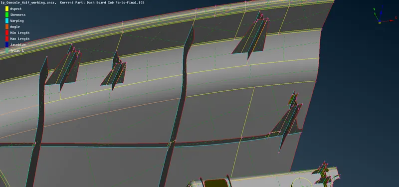
PARENT GEOMETRY FOR THE RIBS EXTRACTED MIDSURFACE FOR THE RIBS
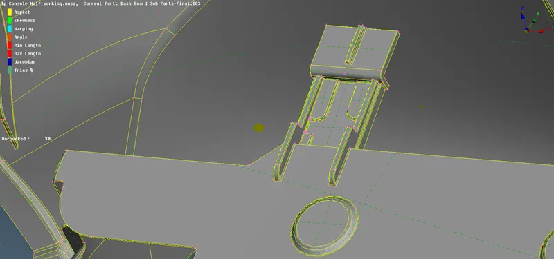
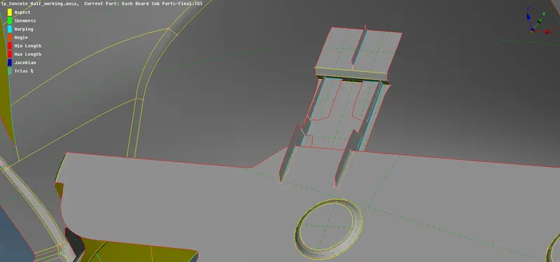
THE MID SURFACES FOR ALL THE DIFFERENT COMPONENTS HAVE BEEN EXTRACTED WITH THE HELP OF THE PARENT GEOMETRY
- Enter the given values in the quality criteria window and try to mesh the component according to the given quality parameters.
- Before applying the mesh on the midsurface component, try to apply the given target element length on the midsurface.
-
To apply the length, change to the Mesh mode from Topo mode, select the Length option in the Perimeters, select the whole mid surfaces, enter the given target element length value and click the middle-click on the mouse to confirm the task.
-
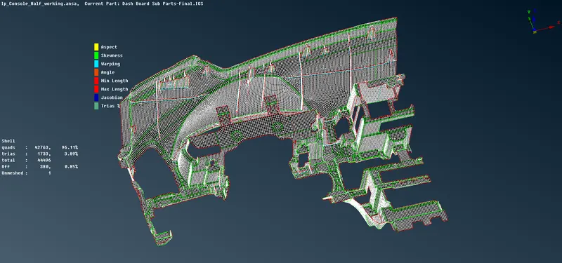
After applying the target element length on the midsurface try to mesh the component. Keep the Mesh mode as it is and click on the Best mesh in the Mesh Generation.
-
Select a face on the midsurface and middle-click to generate the mesh. The mesh generated on the selected face, if the mesh pattern was not good try to reconstruct the mesh by using the Reconstruct tool in the Shell Mesh tools.
- If there are any mesh elements failing for the given quality criteria, try to make them not fail by using the different tools.
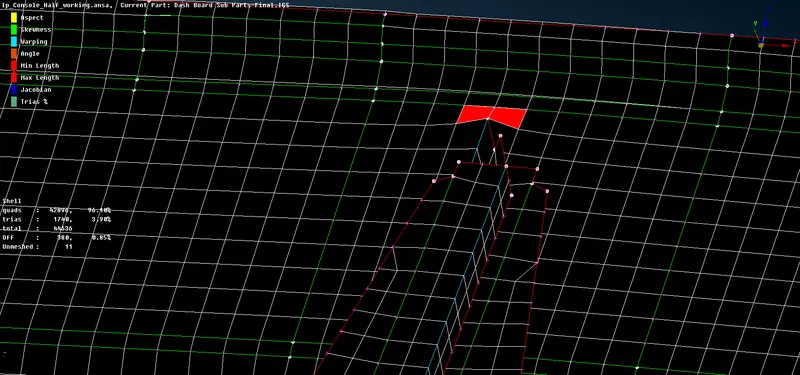
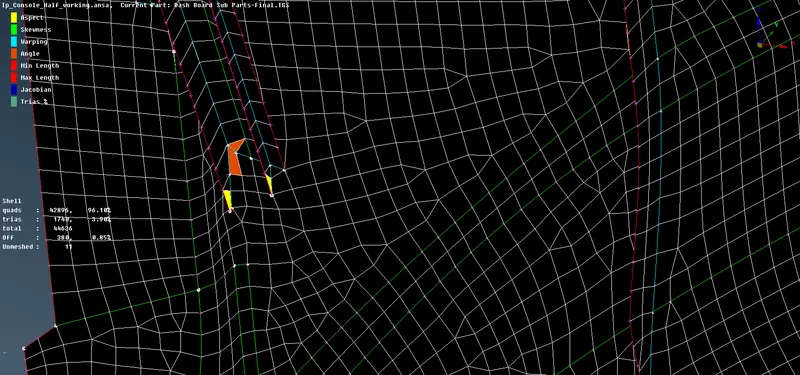
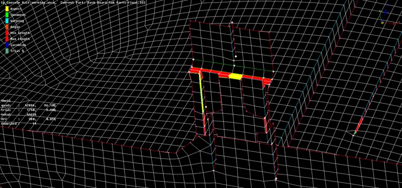
ELEMENTS ARE FAILING AT SOME AREAS WHERE THE SURFACES ARE CONSTRAINED
- In the Mesh mode and at the bottom there are the Elements tools present. In these Elements tools, there are options like Split, Join, Swap etc are present use these tools to clear the mesh quality manually.
- For example, if any less number of elements failing for the Minimum Elements Size try to clear them manually by using the Split option in the Elements tools by splitting the elements and also to clear the Trias in the mesh generated by splitting them and also by joining them by using the Join tool.
- For example, if there are elements failing for the Warpage use the Smooth command in the Shell Mesh in the Mesh mode.
- In this way use different tools for clearing the failed elements in the mesh Jacobian, Skewness, Aspect ratio etc.
- After splitting the elements, the mesh pattern will be disturbed and then use the Smooth tool in the Shell Mesh tools to smoothen the disturbed mesh pattern. If there are a huge number of elements that are failing for the quality try to use the Reconstruct tool present in the Shell Mesh tools.
- If there is a Larger surface area use the Cut option in the Faces tools in the Topo Mode to split the surfaces into small faces and then mesh generate the mesh. Follow this procedure for better mesh flow. Try to split into a number of portions on the surfaces.
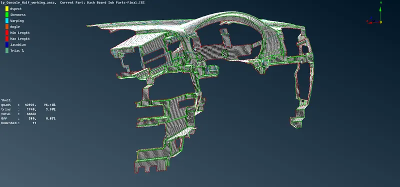
THE MESH IS GENERATED ON THE EXTRACTED MIDSURFACE
- After meshing the Mid surface, Thickness must be assigned to the Midsurfaces.
- Use the Set PID tool to apply the Thickness by creating a Property ID. Click on the Set PID tool and select the whole surface because the total surface is of the same thickness, a pop-up window will be displayed in that enter the thickness value and select a proper colour in the Colour-edit and click on the OK button. If there is any varying thickness in the given model then the property applied should be different for different surfaces.
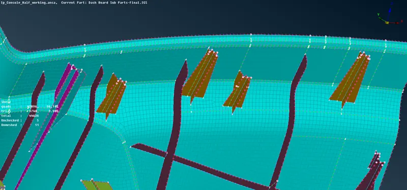
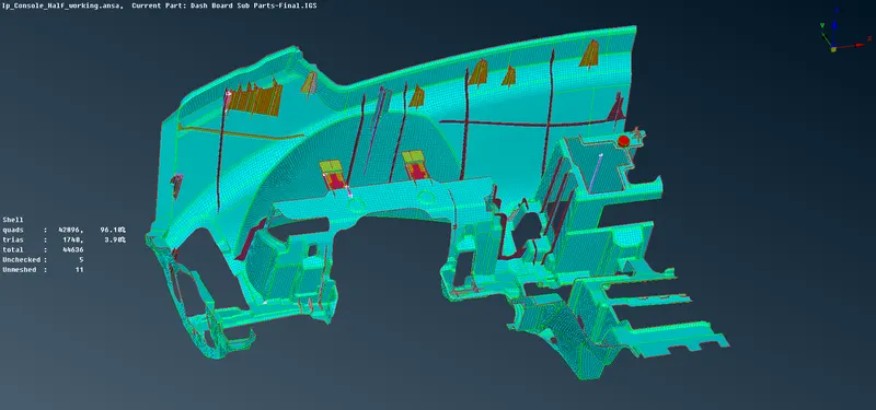
THE PID'S HAVE BEEN ASSIGNED TO THE DIFFERENT SURFACES OF THE MODEL
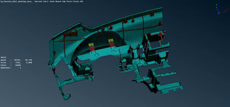
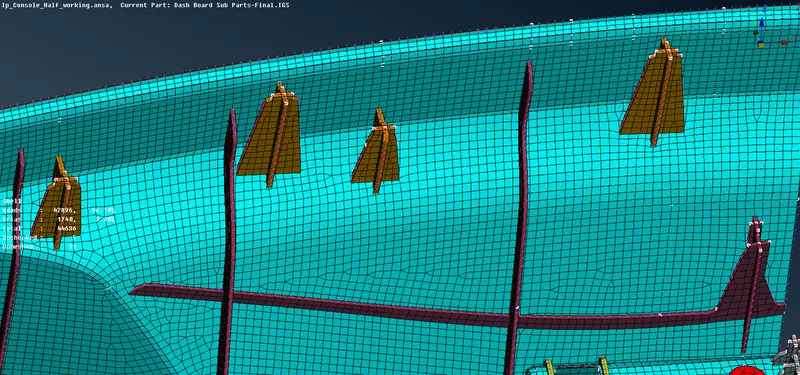
VISUALIZING THE THICKNESS ASSIGNED TO THE DIFFERENT SURFACES
- Apply PID's for all the surfaces like ribs, doghouses, circular surfaces etc by checking the length of the surface using the parent geometry. After doing all this save the model by using the Save as an option in the File menu.
Conclusion:
For the given component, the geometrical errors have been checked and the mesh is generated with the given element Quality criteria. After meshing the component the thickness has been assigned to the different surfaces on the model.