Project 1
AIM:
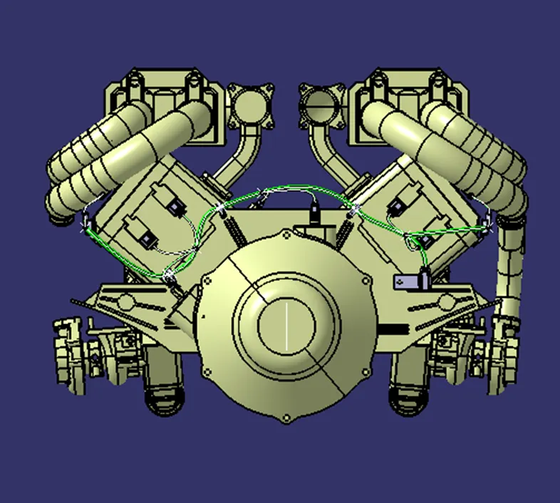
The aim of this project is to create electrical routing for the V-8 engine with having 16 cylinders. It is required to create a proper routing by using guiding channel, connectors used in near Cam shafts and near cylinders and finally to Flatten the required model.
General procedure for Creating routing for the model:
- Download the connectors required for the model and also supports devices.
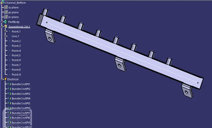
- Create a Guiding Channel with necessary dimensions so that the routing doesn’t effect by the heat of the engine and apply electrical definition to it.
- Apply Electrical properties to the downloaded CAD models like bundle connection point, Connector connection point, cavity connection point and support definitions required for support devices.
CONNECTORS UDED IN ROUTING FOR ENGINE:
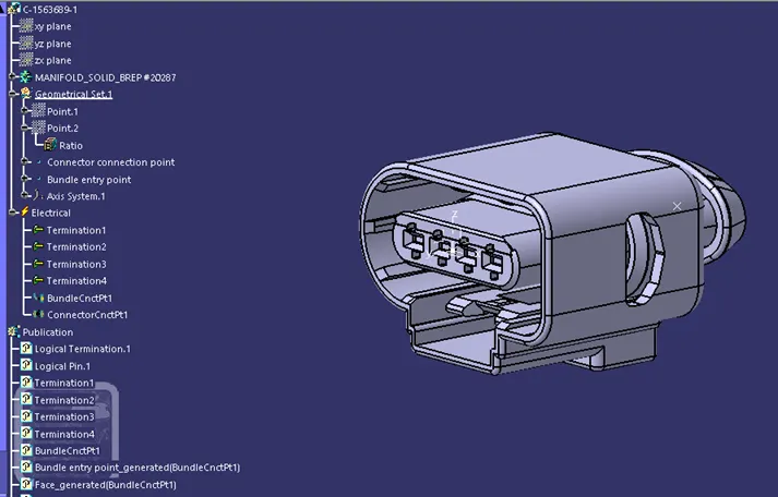
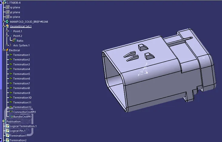
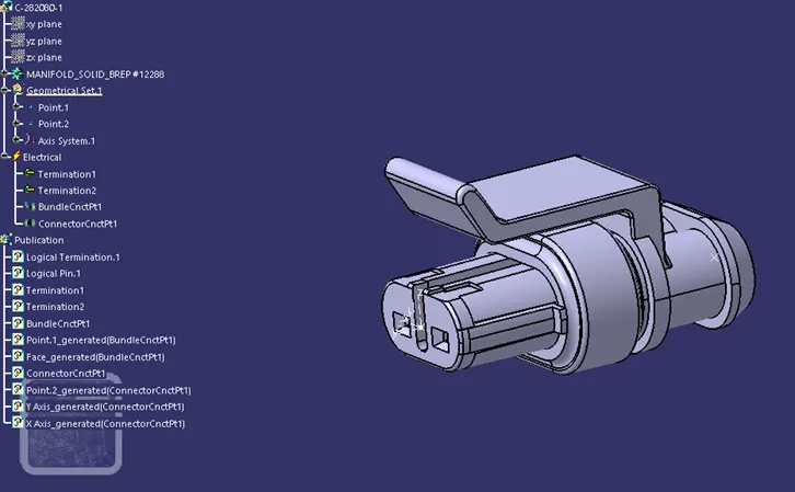
SUPPOURT DEVICES USED IN ROUTING FOR ENGINE:
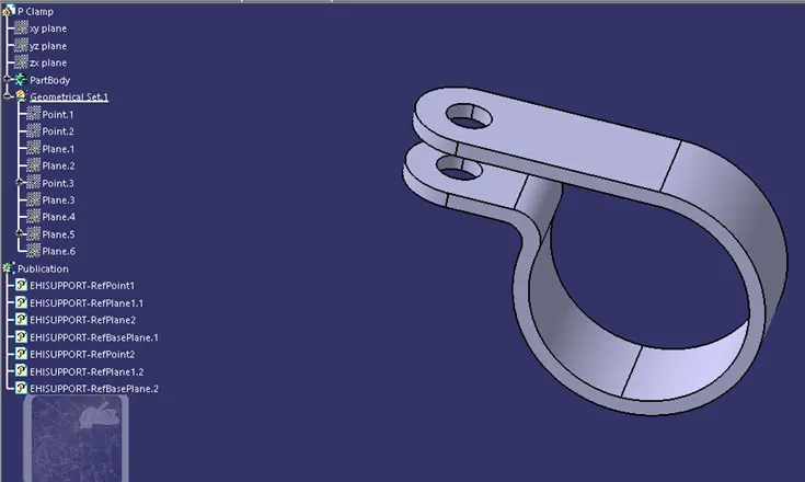
CREATING ASSEMBLY CONTEXT:
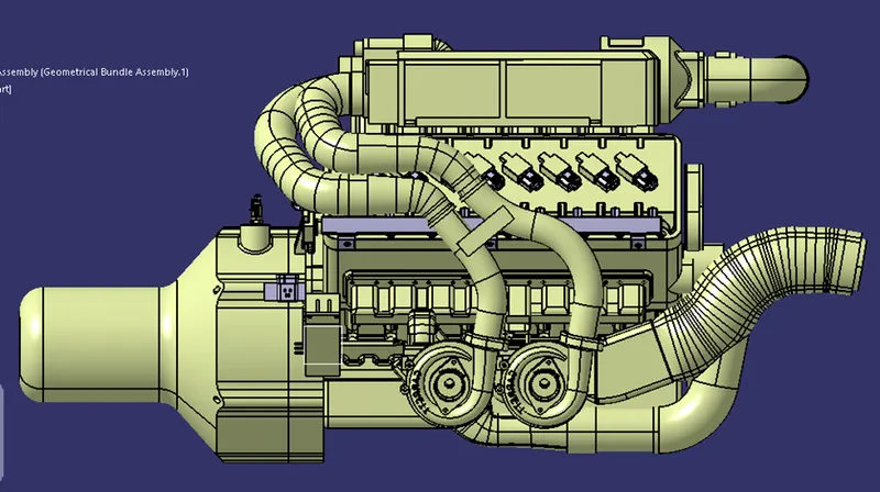
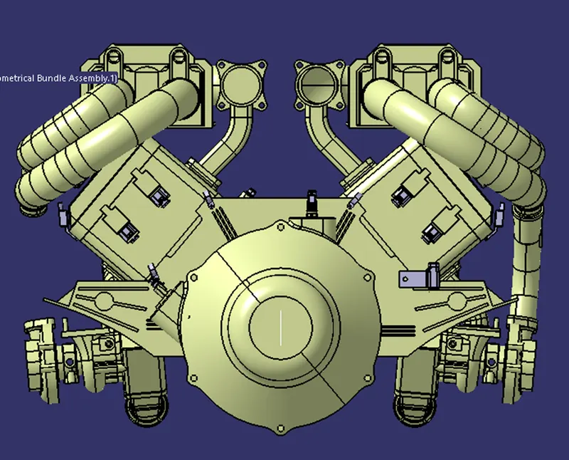
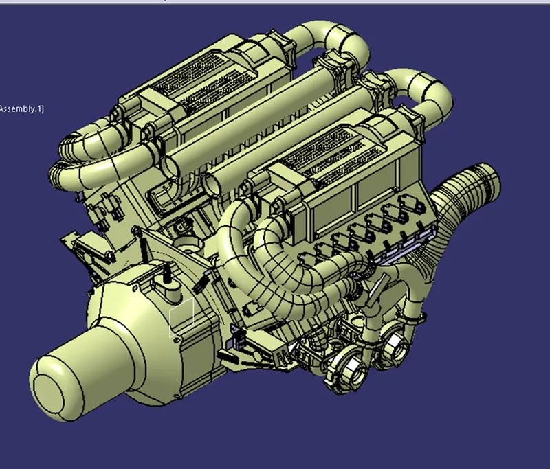
- Import the required files like Engine CAD model, connectors required for Routing and also support devices.
- Move each and every connector in a required position by using move command and snap faces whenever required
- Place the support devices when required.
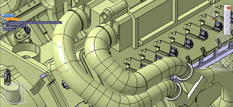
CREATING MULTI BRANCHABLE SEGMENT:
Create Geometrical bundle definition in the Geometrical bundle assembly which already connectors placed inside in it.
By using the multi branchable definition, create routing for all connectors.
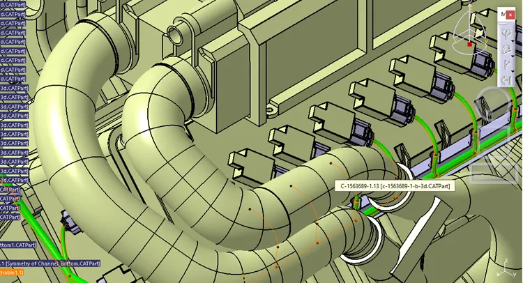
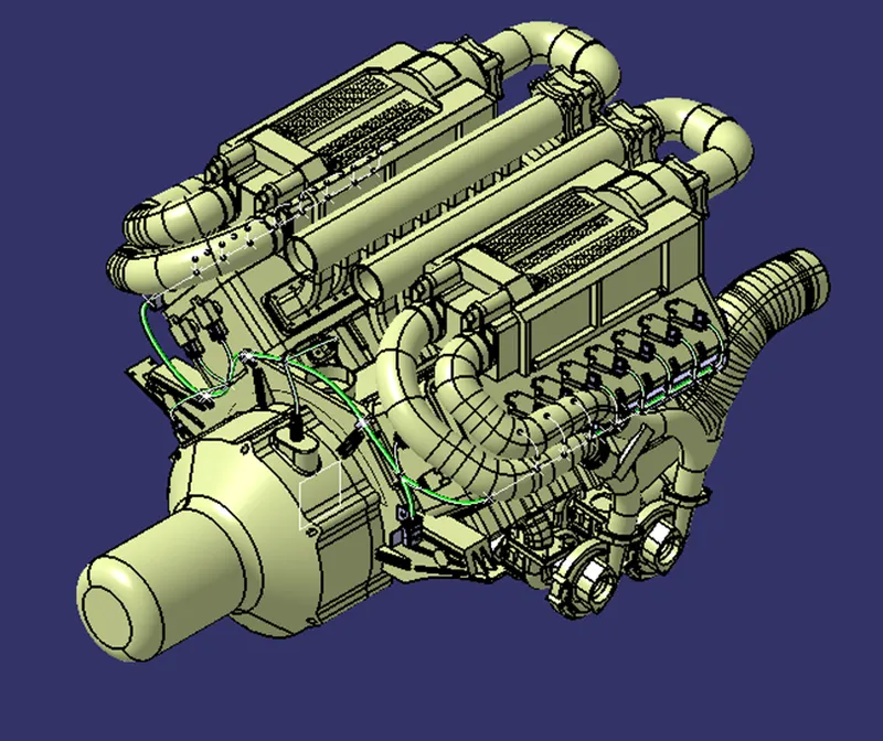
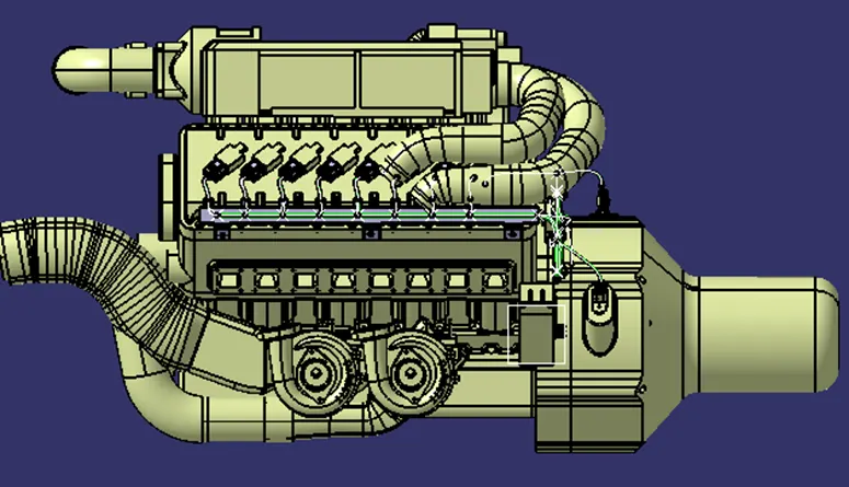
CHECKING BUNDLE CONNECTIVITY:
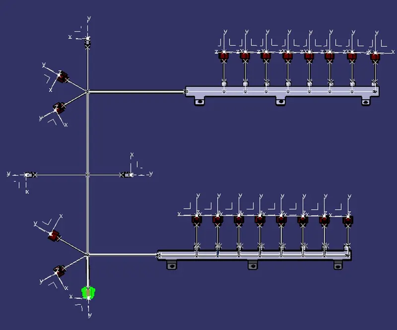
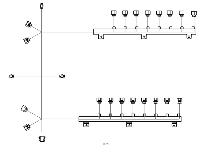
CREATE FLATENNING:
Flatenning is used to convert model into drawing in a single plane which used to understand universally.
CONCLUSION:
- The routing is done completely for the given CAD model of engine with necessary connectors by using different work benches in CATIA software.
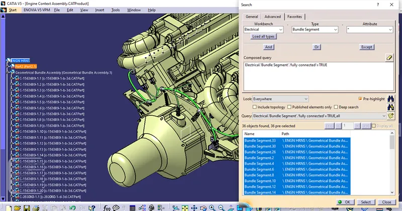
- Bundle connectivity is checked and hence it was fully connected.
- Proper flattening is created