Photo Realistic Rendering
DESIGN AND ASSEMBLY OF AMERICAN CHOPPER USING SOLID WORKS
INTRODUCTION:
The project report contains detailed explanation about designing of an American chopper and tools used to create American chopper which designed in SOLIDWORKS from each part modelling to final assembly.
OBJECTIVE:
The objective of this project is to develop the design of American chopper with individual design of each component and assembling it to get required American chopper.
The following steps where undertaken while designing the American chopper:
- Designing of individual components of an American Chopper.
- Assembly of American chopper.
- Set up decals, Scene , Lights, and cameras.
- Final rendering of American chopper.
TOOLS USED IN SOLIDWORKS TO DESIGN AMERICAN CHOPPER:
SKETCH:
Sketch is a 2D representation of the model with respect to plane/view of the part. In solid works there are sketch option to create a sketch. There are so many sketch tools available like circle, rectangle, arc, spline, line, ellipse etc. we can create a new sketch by selecting the plane or surface of part model or we can edit the previous sketch also. Every 2D sketch need to be fully defined/ constrained to convert into 3D model or a part.
EXTRUDE BOSS/BASS:
Extrude is a type of tool to convert a 2D sketch into 3D model for a given dimensions.
SWEEP:
Sweep feature is used to generate a 3D model part by using two 2D sketches which should not in same plane.
REVOLVE:
To create a cylindrical shaped part with the help of 2D sketch in a plane. The sketch revolves around the reference axis. This reference axis of revolve should be in sketch or origin or any other sketch(line).
LOFTED BOSS/BASS:
Loft is like sweep feature. The lot feature tool allows you to generate complex geometry in a single feature. The 3D part on loft tool is generated by interpolating surfaces between various cross sections of a model. These cross sections can be sketches, faces, edges. In the loft created model, these cross-sections are also known as loft profiles.
EXTRUDE CUT:
Extrude cut is a cool feature which helps to subtract materials from created 3D modelled part. This is quite opposite of Extrude boss/bass tool. This tool is mainly used for creating holes, groves etc.
SWEEP CUT:
The exact 3D modelled part is subtracted from the original 3D part. This is similar to extrude cut. If we want to subtract materials with complex shape sweep cut is used.
REVOLVE CUT:
The subtraction of materials along a cylindrical path of a modelled part with the help of 2D sketch and reference axis. Revolve cut, Sweep cut and extrude cut comes under the same features of subtraction of materials.
DOME:
Dome can be applied on single or planar or non-planar faces. The centroid of a dome lies on above the face. This feature allows to apply domes to irregular shaped counters. There are two types of domes available in solid works, they are circular dome and elliptical dome.
FILLET:
Fillet creates a round shaped edge to a sharp edge. Every product should not contain a sharp edge. Due to this stress is involved. So, to get stress concentration fillet is necessary to overcome stress.
CHAMFER:
Chamfer is mainly used on shafts and cylinders to fit onto a hole freely with less effort. Also, it converts a sharp edge into a slope slightly rather than being perfectly square. They are few types of chamfers like angle-distance chamfer, distance-distance chamfer etc.
OFFSET:
One or more sketch entities, selected model edges, or model faces by a specified distance. For example, you can offset sketch entities such as splines or arcs, set of model edges, loops etc. you can offset closed sketch, lines ,arcs and splines.
TRIM ENTITIES:
Erasing of sketch which should not need can be trim by using trim entities. Power trim is the most used tool on 2D sketch. We can erase either in 2D sketch or on 3D plane. On the trim entities one of the useful tools, extend entities which is quite opposite to trim. By using this tool it extend up to the sketch which going to coincide on the same path. This mainly works of extending the arc, line, spline etc.
DYNAMIC MIRROR:
Dynamic mirror has a silent feature and important tool in solid works. It reduces the sketch by selecting the mirror reference line. As you sketch entities, they are mirrored about the pre-selected sketch entity.
COMBINE:
Combine tool combines the 2 or more parts with a minimum interference to generate into a single product.
SHELL:
To convert a complete solid body into a close shell type box with a user defined thickness, shell feature is used.
CIRCULAR PATTERN:
To convert a feature or body or sketch in a circular pattern , this tool is used by selecting a reference circle or circle edge or point.
LINEAR PATTERN:
This is similar to circular pattern but it converts the face or body or sketch in a liner way by selecting a reference as a linear line or a spline.
PROJECT CURVE:
To project a 3D curve with the help of two 2D sketches project curve tool is used. It is not possible to draw a direct 3D curve. So, this helps to project a 3D curve instantaneously.
EXTEND SURFACE:
Extend surface is used to extend the surface which is already created. There are different options available on the extend surface. We can extend the surface as same surface or we can extend the surface tangent to the surface.
LOFTED SURFACE:
Loft surface are surfaces generated by multiple 3D curves or existing edges creating a smooth tangency between the selected curves.
SWEAPT SURFACES:
Sweep surfaces are the surfaces that are generated from a section curve positioned along a path.
FILLED SURFACE:
The filled surface feature constructs a surface patch with any number of sides, within a defined boundary by existing model edges, sketches, or curves, including composite curves.
SURFACE KNIT:
Surface knit is used to knit the two free edges or open edges together. It reduces the gap between two edges of the surface.
EXTEND SURFACE:
Extend surface is used to extend the surface which already created. They are few options available on extend surface. We can extend the surface or we can extend the surface tangent to the surface.
APPEARANCES:
To visualize the part while designing appearance tool is used. It doesn’t affect the physical properties even when user specified the material of appearances. Every material is assigned a default appearance that emulates the look of material.
DESIGN METHODOLOGY OF AMERICAN CHOPPER
TRANSMISSION BELT:
The belt is a flexible element , used to transmit power form one shaft to another shaft. Power transmission belts are divided into 4 types, they are,
- V-belt
V belts are used to transmit moderate power from one shaft to another shaft when two pulleys are near to each other. To drive the V-belts, pulley also should be in V shape to avoid misalignment and to transmit power easily
- Flat belt
Flat belts are used to transmit high power from one pulley to another pulley when pulleys are not more than 8 meters a part. Flat belts have greater efficiency to transmit power and it is cost effective. They are very easy to install
- Circular belt
Circular belt have circular cross section. These belts are used to transmit high power when pulleys are more than 8 meters a part.
- Timing or toothed belt
These belts are used to transmit power and motion with accurate timing. These belts having toothed surface with meshed with pulley. It is not an ordinary belt to work on friction. It is most expensive belt as compared to another type of belts.
The material used for belts and ropes must be strong and flexible and should have a high coefficient of friction. So belts plays a major role in power transmission. Leather, cotton or fabric, rubber and balata materials are used in belts.
Design of transmission belt:
For American chopper, Flat belt is designed to transmit power from engine shaft to gear box with a 350mm centre distance. The width of the belt is 88mm and thickness of the belt is 3.5 mm.
Features used in transmission belt.
- Extrude boss/bass
- Fillet
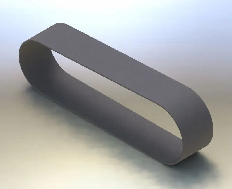 ISOMETRIC VIEW OF TRANSMISSION BELT
CHAIN:
Chain drive transmission is the way of mechanical power transmission by using chain links. This type of power transmission transmission is used in motorcycles and bicycles. It consist of flexible links which completely manufactured with metals. It consist of endless series of chain links as roller chain which meshed with toothed sprocket gear. Chain drive can transmit power in high velocity ratio up to 8:1.
Design of chain:
For the American chopper, Chain is designed to transmit power from Gear box (small chain sprocket) to rear wheel( large chain sprocket) with a center distance of 1330 mm and pitch of chain link is 15.30 mm. the thickness of the link used to design a link id 3 mm.
Features used to design chain in Solid works.
- Extrude boss/bass
- Fillet
- Curve driven pattern
- Add and insert blocks
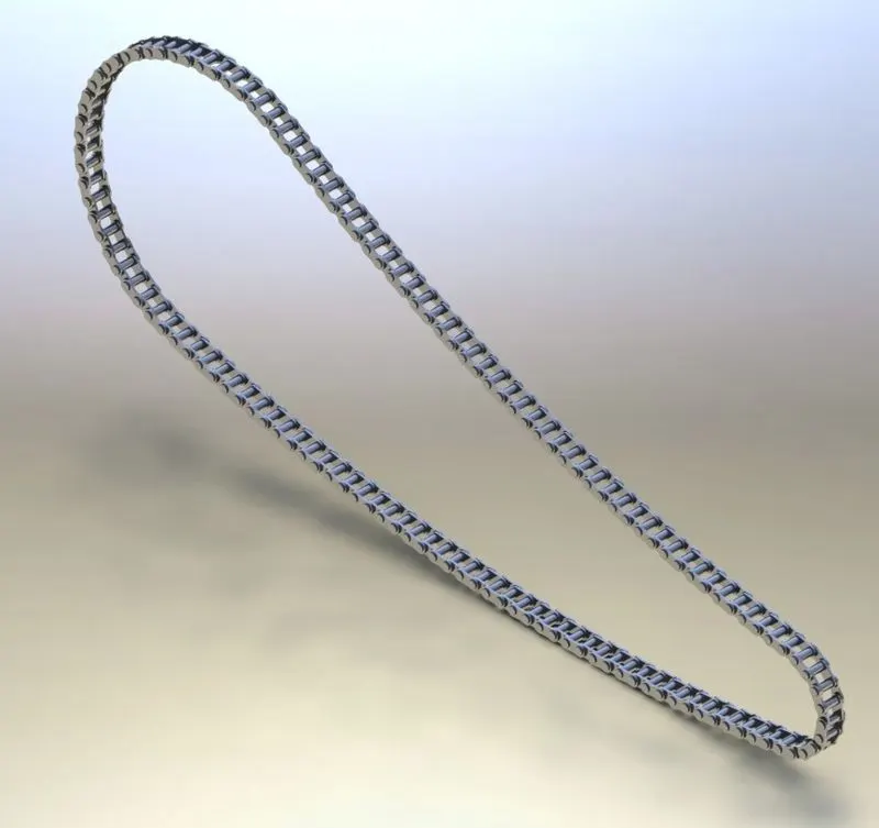
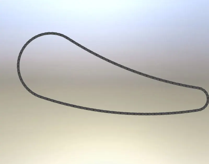
ISOMETRIC AND SIDE VIEW OF CHAIN
KICK STAND:
A kick stand is a device used in bicycle and motorcycle that allows the bike to kept upright without leaning against another object or the aid of a person. A kick stand is made of generally a metal that flips down from frame and contacts the ground. It generally located at the middle of the bike towards the Rear side.
Design of kick stand:
In the American chopper the height of kick stand is about 130 mm long. The kick stand is in elliptical shape. Both the elliptical entities are lofted with a curve path is basic radius is nearly 150. The appearance of the Kick stand is Chromium.
FEATURES USED TO DESIGN KICKSTAND IN SOLID WORKS:
- Lofted boss/bass
- Dome
- Fillet
- Extrude boss/bass
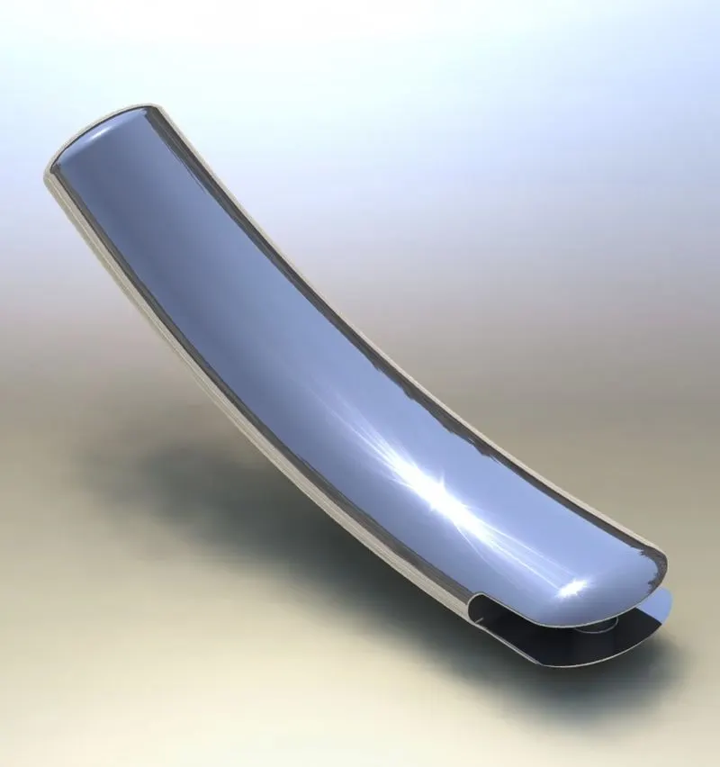
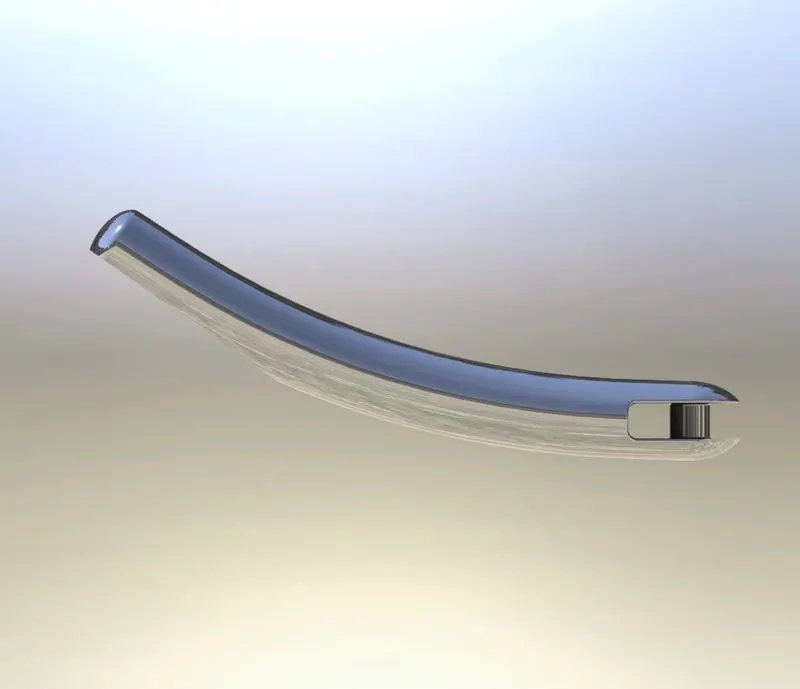
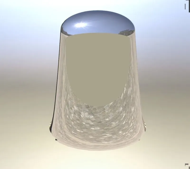
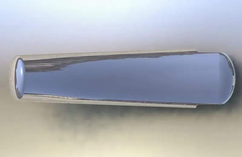
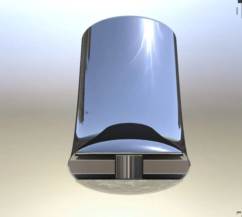 ISOMETRIC AND SIDE VIEWS OF KICK STAND
PEDAL:
Pedal is very useful for comfort of rider to support legs. Pedal is used to shift gears and breaks of a bike. Pedal is fitted to chasis frame of a bike to provide an extra support.
Design of pedal:
The length of a pedal is about 255mm long and 84 mm height from the fitted rod. It is designed to comfort of rider with three support holders. It is completely a curved shape structure.
FEATURES USED TO DESIGN PEDAL ON SOLID WORKS:
- Extrude boss/bass.
- Fillet
- Chamfer
- Linear pattern
- Revolve
- Dome
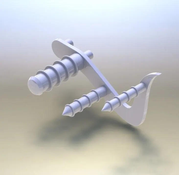
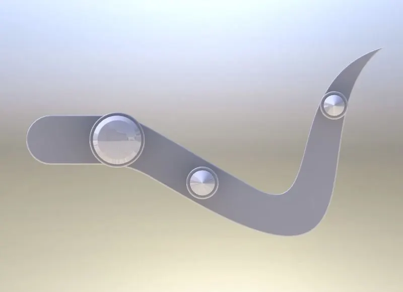
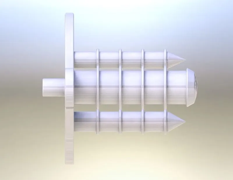
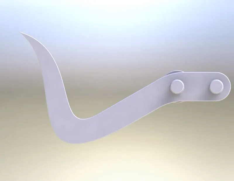
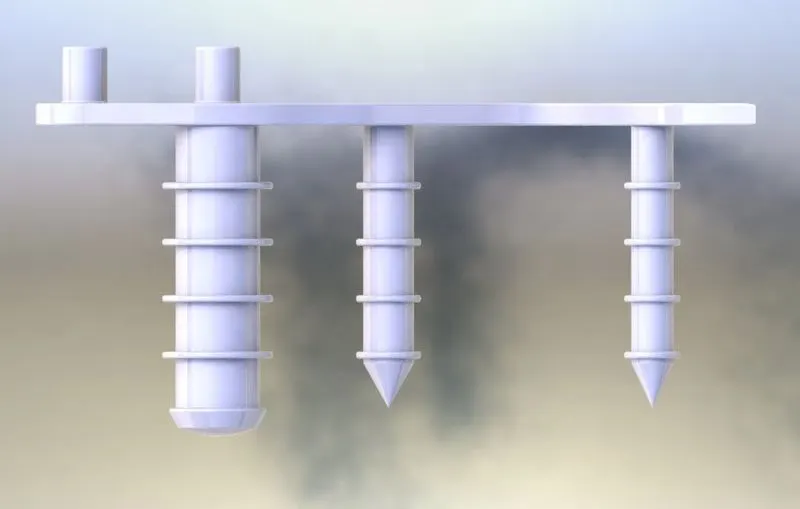 ISOMETRIC AND SIDE VIEWS OF PEDAL
CHASSIS:
Much like human spine and supporting skeleton, a motorcycle chasis holds everything together from engine , suspension, wheels, fork, fuel tank, seat, battery box, pedal etc. Every automotive chasis is in hallow shape tube to reduce the weight and decrease the bending stress. Hallow shape tube has a less bending nature as compared to the solid tube. There are few types of motorcycle chasis.
- Back bone frame chasis: In this type of chasis the engine is usually hangs off the chasis and isn’t consider as stress member. It is most affordable type of chasis and it is simple construction. On the other side, the backbone frame offers less torsional rigidity and strength and hence it is used in low-cost motorcycles with smaller engines
- Single cradle frame: It is also known as single downtube or diamond frame. It is commonly used in budget friendly motorcycles. It is similar to bicycle frame. In this type of frame only engine is consider as a stressed member and all other parts are light in weight. It is not as much of strongest as all other frames.
- Double-cradle frame: It comsist of two tubes running beneath the engine in order to support. This is cost effective frame, but it provides a good strength and rigidity. They are mostly seens on bikes like Pulsur and Royal Enfield.
- Perimeter and trellis frame: A perimeter frame or a twin-spar frame has two box section tubes that are fused to fork at one of pivot. On the other hand the engine is suspended od it. While trellis frame is similar to perimeter frame. In place of aluminium or steel beams, a trellis frame uses an assortment of short sized or aluminium tubes welded together in a triangulated form. This frame is lighter.
Design of chasis:
The chasis of American chopper is designed to mount parts like , rear wheel, fork, engine, kick stand and gas tank with seat. It is hallowed tube shape structure. The complete design is in 3D shape by using project curves method by using two 2D sketches.
FEATURES USED TO DESIGN CHASIS IN SOLID WORKS:
- Sweep boss/ bass
- Extrude boss/ bass.
- Projected curves.
- Split
- Mirror
- Revolve
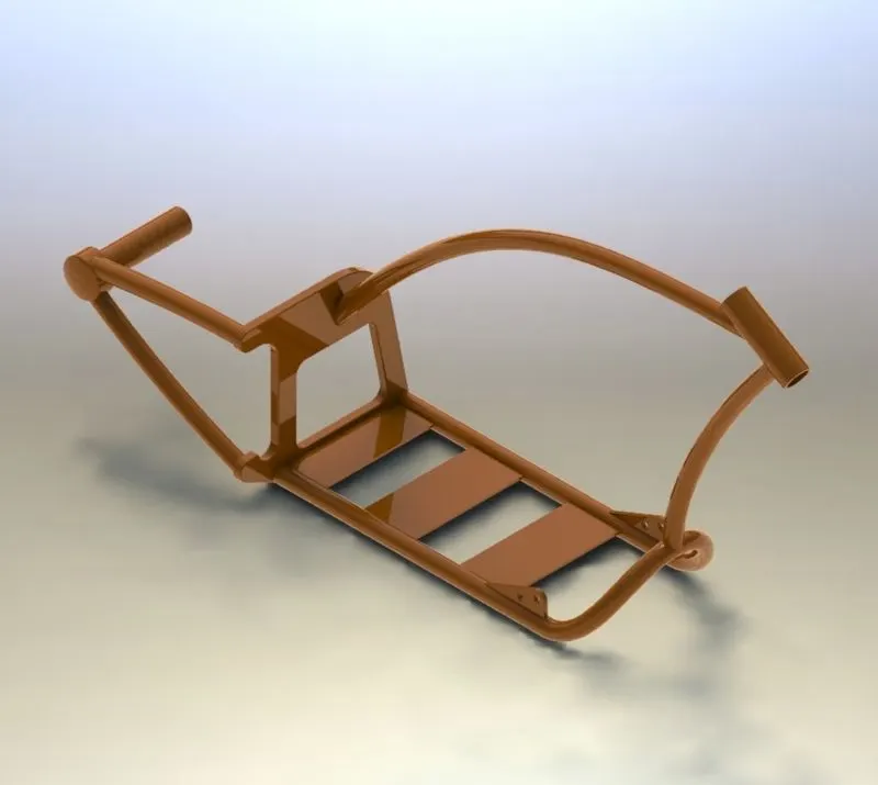
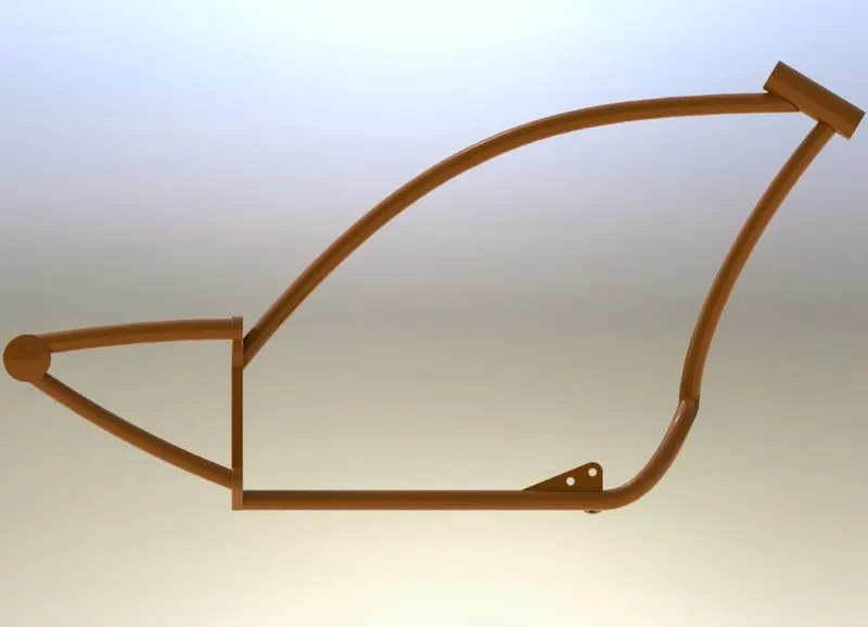
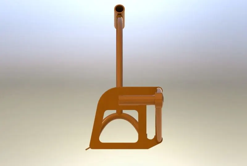
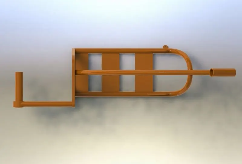
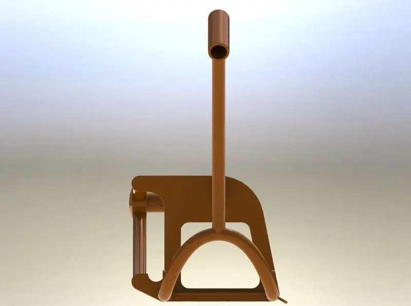
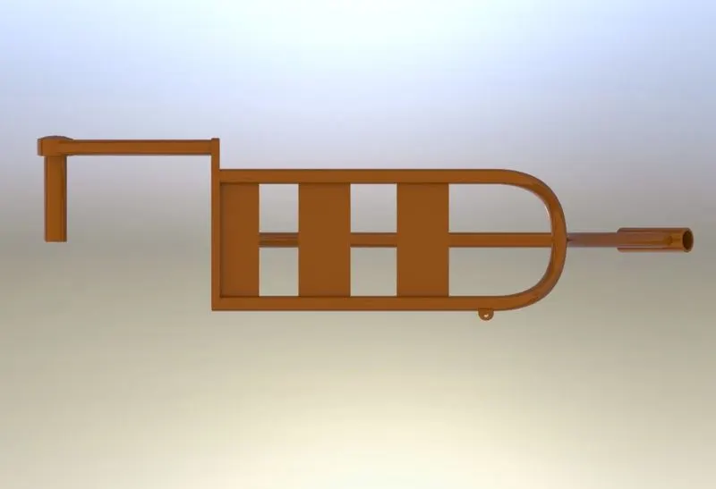
ISOMETRIC AND SIDE VIEWS OF CHASIS
ENGINE:
Engine is a mechanical device used to transmit mechanical power. Every mechanical engine works on the Thermodynamics first law of conservation of energy. It states that energy neither be created nor be destroyed but changes from one form of energy to another form to crate mechanical work. In mechanical engines chemical energy is converted into heat energy by burning the fuel and this heat energy is created into work. The chemical energy is the form of fuel. Fuels are mainly three types, they are Solid fuel, Liquid Fuel and gaseous fuel. Liquid fuel i.e., petrol is mostly used in bikes. Engines are classified as two types. They are Two-stroke engine and four-stroke engine. Now a days four- stroke engines are widely used in automotive sector.
DESIGN OF ENGINE:
In this American chopper V-Engine is designed. V-Engine consist of two-cylinder bores in V shape and each cylinder bores has equal number of valves. It is oil cooled and air-cooled engine with 14 air fins and mufflers of each cylinder is fitted individually. The engine consists of a starter motor, two belt pulleys with diameter 60mm and 70 mm and a chain driven pulley of diameter 99mm. the shape of muffler is specially designed to avoid contact of riders right leg is on pedal and also muffler didn’t interference with chasis to avoid heat from it.
FEAUTURES USED TO DESIGN ENGINE ON SOLIDWORKS:
- Extrude boss/ base
- Sweep boss/bass
- Extrude cut
- Project curve
- Chamfer
- Fillet
- Revolve
- Circular pattern
- Linear pattern
- Dome
- Split
- Four round Fillet
- MirroR
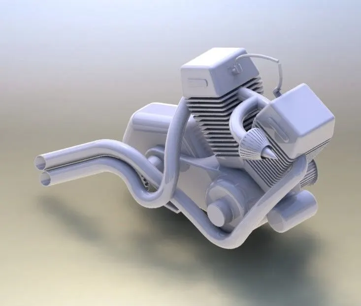
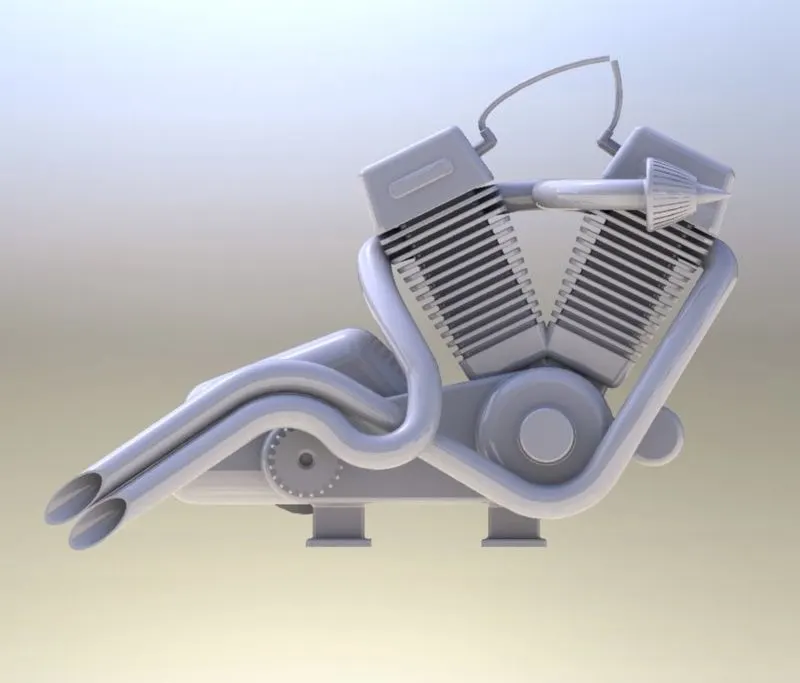
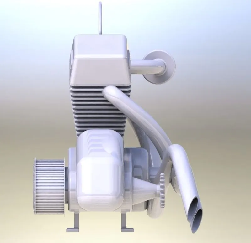
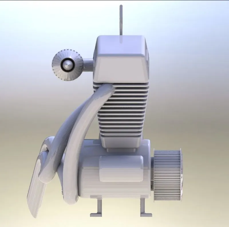 ISOMETRIC AND SIDE VIEWS OF ENGINE
OIL TANK:
Oil tank is used to store lubrication oil to cools the engine temperature and make a smooth ride.
DESIGN OF OIL TANK:
The thickness of oil tank is 3mm. the width on botton of the lubricant oil tank is 100 mm on one side and another is in the shape of cylinder with tangent model of angled lines with oil tank length 230 mm. on the top of the oil tank is designed with slope by using intersection of two parts of mating region. The height of oil tank on one side is 42 mm and the other side of semi cylinder shape is about 166 mm. The appearance of the oil tank is given as siena color and it is a shell type oil tank.
FEATURES USED TO DESIGN OIL TANK ON SOLID WORKS:
- Extrude boss/bass
- Combine
- Fillet
- Shell
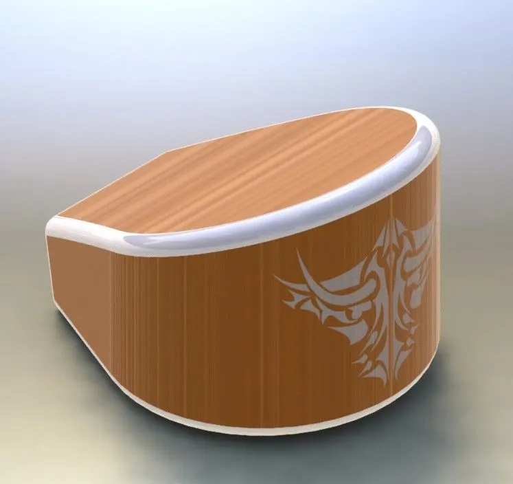
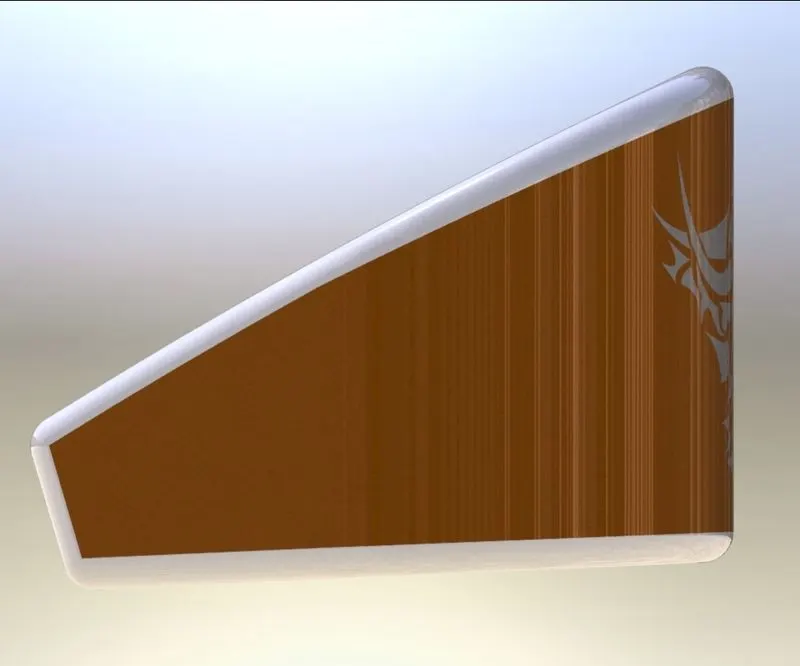
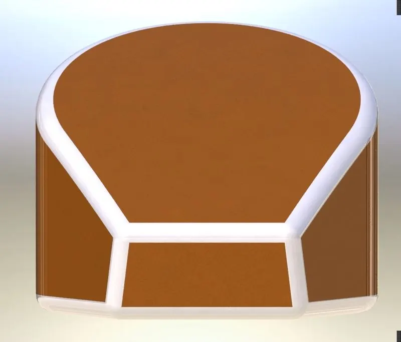
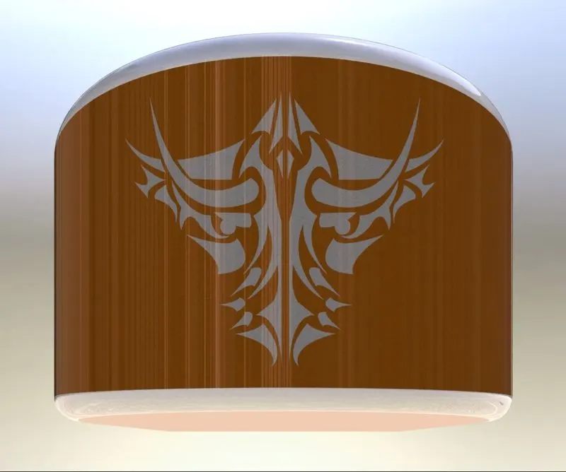
ISOMETRIC AND SIDE VIEWS OF OIL TANK
FRONT FORK:
The motorcycle fork is connected with front wheel and fork rotates to give a steering mechanism of a bike.motorcycle’s front wheel amd axle to its frame, typically an yoke, also known as triple clamp, which consist of upper yoke joined to a lower yoke via steering stem. Most of the forks incorporates front suspension, front brake and allows front wheel to rotate about steering axis so that bike mat steered either left nor right.
Telescopic is a type of fork which widely used. Because it contains suspension components internally on fork tubes. The main advantage of telescopic fork are
- Simple in design and relatively cheap to manufacture and assembly.
- Clean and simple appearance that bikers find more attractive
- Lighter than older designs.
DESIGN OF FRONT FORK:
The length of the fork tube is 1330mm. the diameter of fork tube is 30mm and diameter of suspension cylinder is 25 mm having suspension cyliner of length 435mm. The starting point of handle bars is 210mm wide with handle bar diameter 35mm. By using two curves a 3D curve is generated by using project curve feature with 273 mm distance from midplane of fork. So that the two handle bars are with a distance of 546mm wide. The lightning system is also designed along with fork with an angle of 62degrees from front plane of fork. So that the lightning obtains with a lower angle clearly for 4 degrees from the front view of chopper. Clutch, Break and its cables and also grip os handle is also designed.
FEATURES USED TO DESIGN FRONT FORK IN SOLID WORKS:
- Revolve
- Extrude boss/bass
- Linear pattern
- Sweep
- Project curve
- Combine
- Fillet
- Mirror
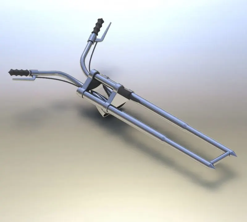
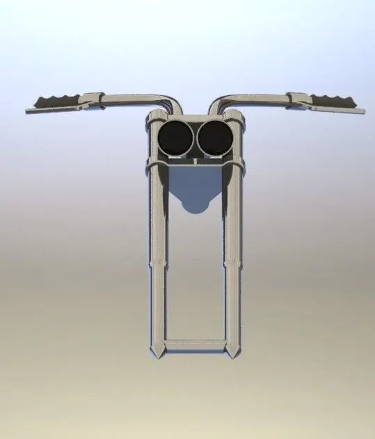
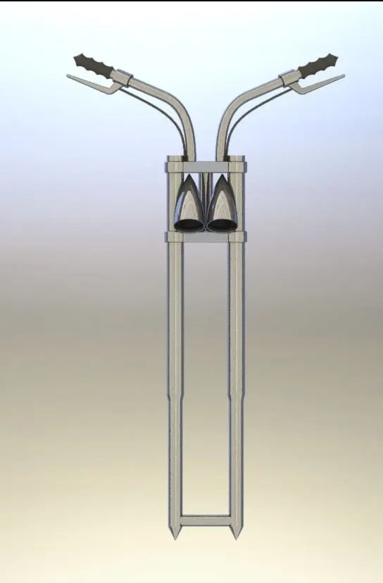
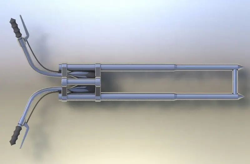
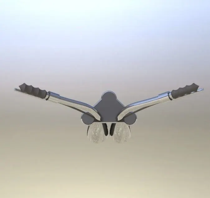 ISOMETRIC AND SIDE VIEWS OF FORK
GAS TANK:
Generally gas tank is used to store fuel of bike. The fuels like petrol is stored widely. It was manufactured by steel sheets to avoid leakage of fuel.
DESIGN OF GAS TANK:
In the front plane using splines project a 3D curve and generated a sweep surface to create a tank with dimensions required. Draw another sketch on bottom plane to create a seat of rider. Now create a 3D curve by using another curves and generate a boundary surface and mirror it. Close the complete open surface by using boundary surface along so path. Now apply appearance od siena and cotton fabricate material to seat.
FEATURES USED TO DESIGN GAS TANK IN SOLIDWORKS:
- Sweep surface
- Fillet
- Surface loft
- Surface knit
- Project curve
- Fillet
- Mirror
- Split
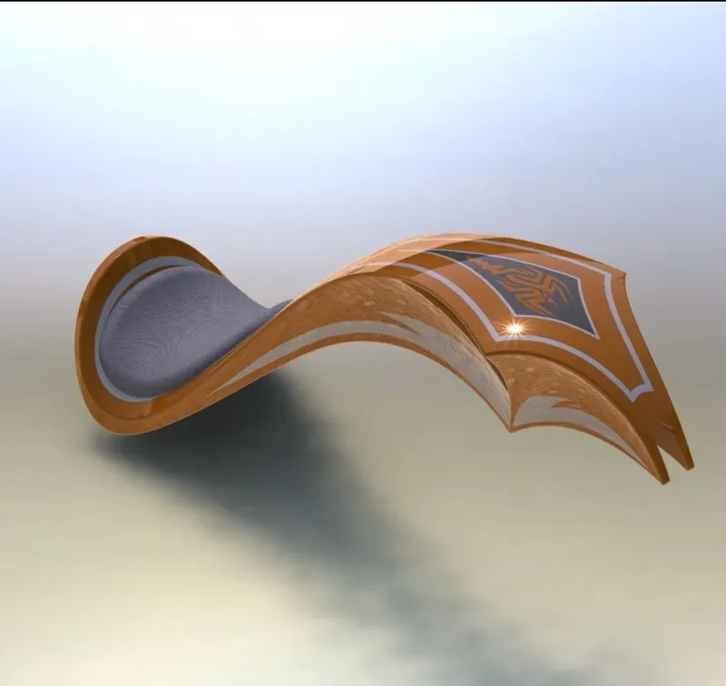
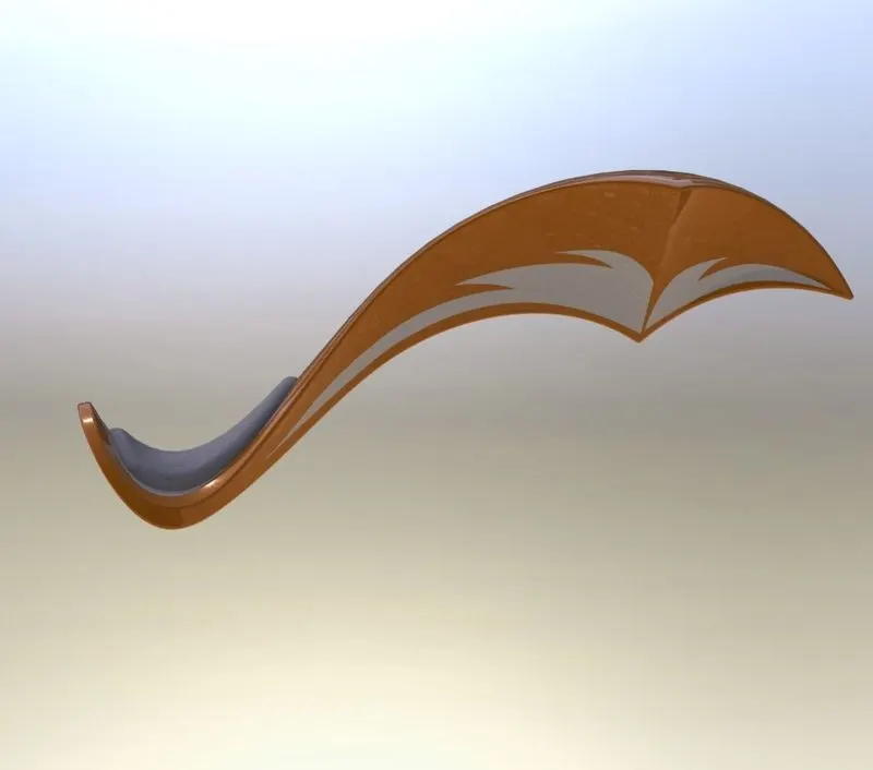
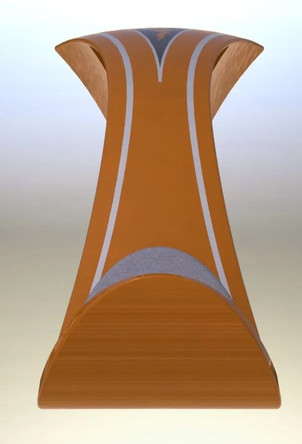
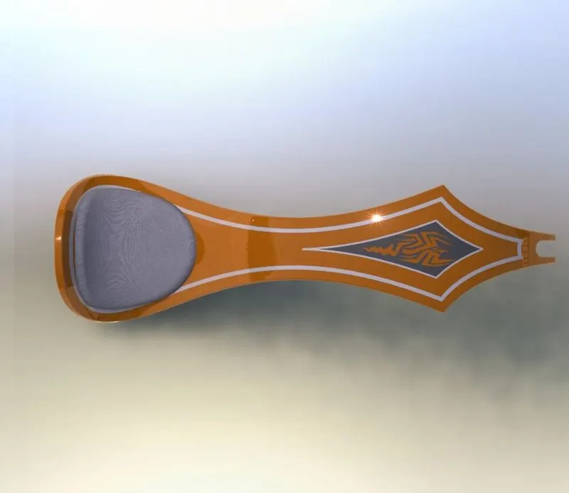
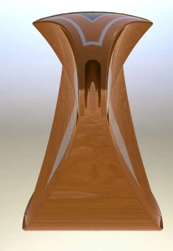 ISOMETRIC AND SIDE VIEWS OF GAS TANK
FRONT AND REAR FENDERS:
Fender is an american engish terrm of an automobile part. Fenders are also known as mudgaurds. It reduce the amount of grime sprayed onto your bike. Fenders cary the benefit of reducing the amount of grit that can work onto your bike’s moving component when riding in wet conditions. This can save your money by prolonging the life of your bike’s components.
DESIGN OF FRONT AND REAR FENDERS:
Front fender:
Front fender is designed with a thickness of 6mm having radius of 125mm for 160mm width of the fender. The distance from orign to center of semi circle is 280 mm. and now revolve arround the axis of plane with an angle of 50 degrees on one direction and 130 degrees on another direction. Apply split feature by creating a new sketch of one side of fender with a spline of radius 180 mm , one point on its center having distance of 128 mm on x direction and 47 mm on y direction.
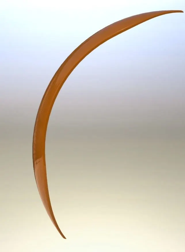
Rear Fender:
Rear fender is designed with a thickness of 6mm and width of 364mm having radius for about 290mm. the distance from center point of arc and orign is 90mm. The required is to be revolve for 10 degree on one side and 140 degrees on another side. Create another sketch of 265 mm and split on the fender. Apply 45 mm fillet on round edges.
FEATURES USED TO DESIGN FENDERS ON SOLID WORKS:
- Revolve
- Split
- Fillet
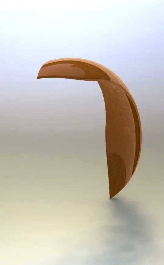
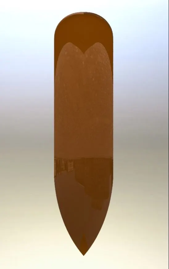
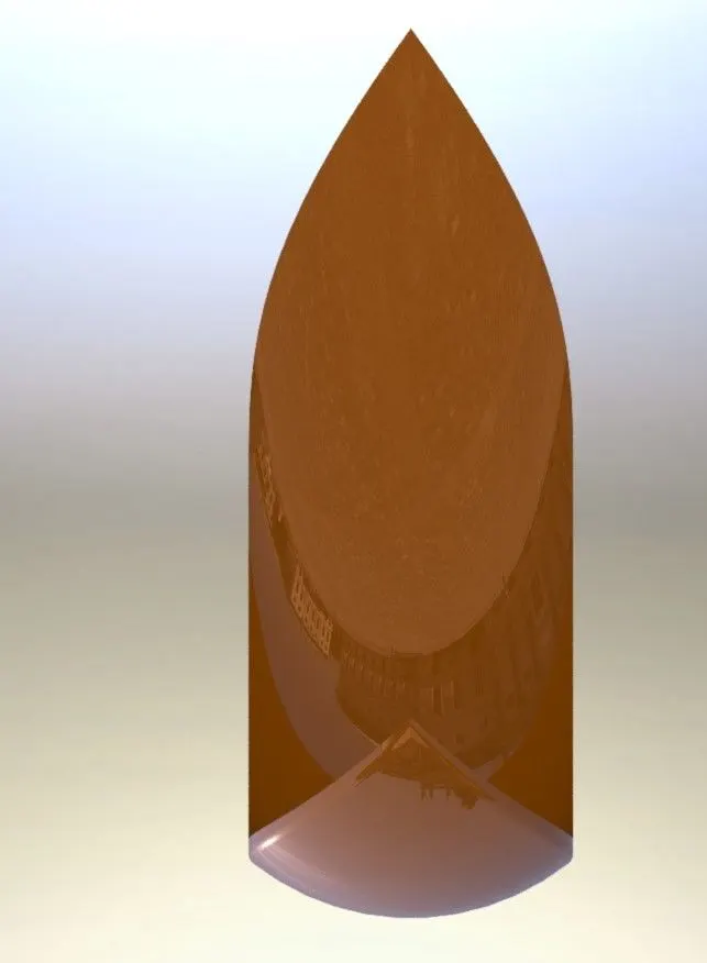
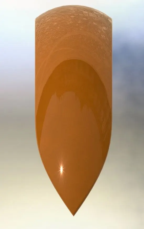 ISOMETRIC AND SIDE VIEW OF FRONT FENDER
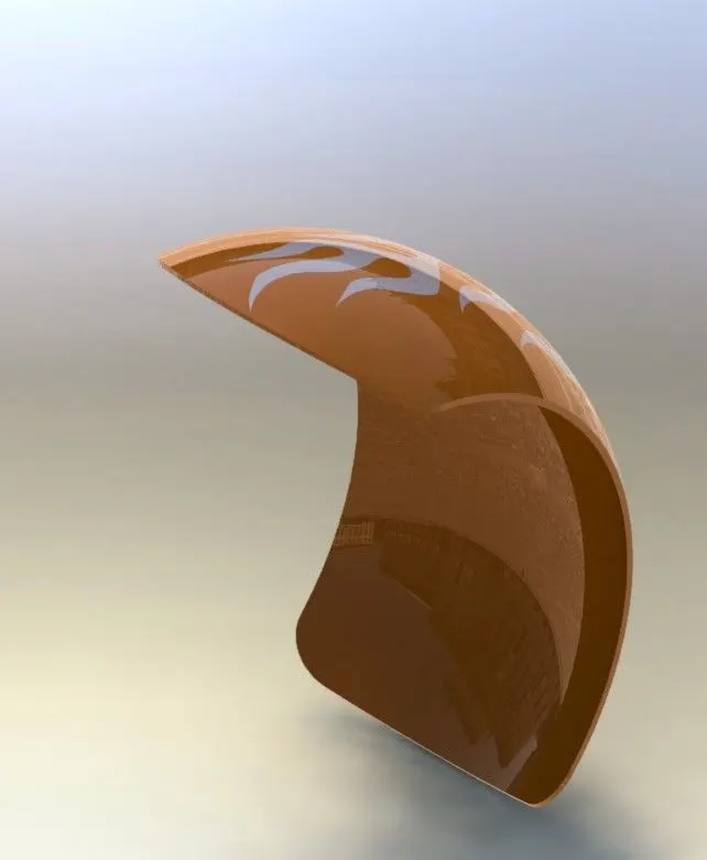
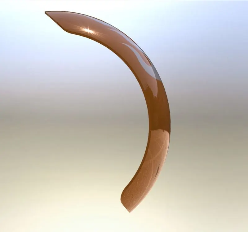
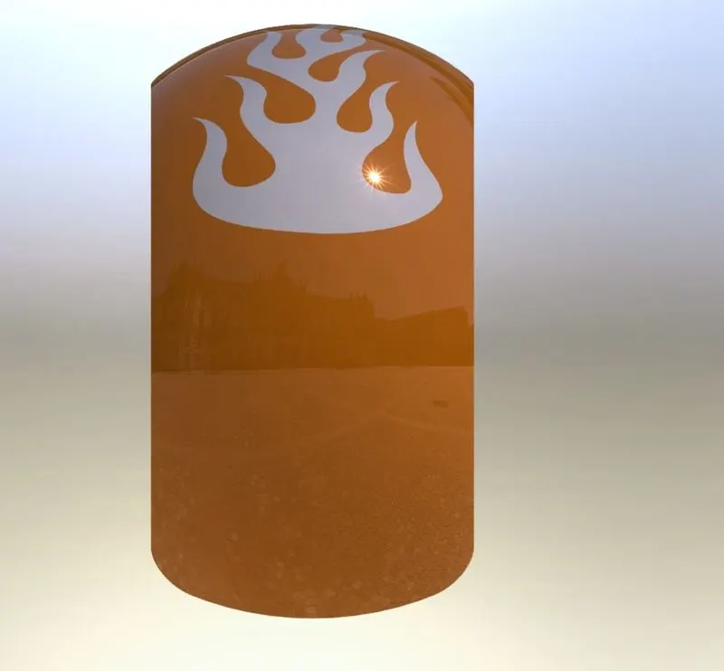
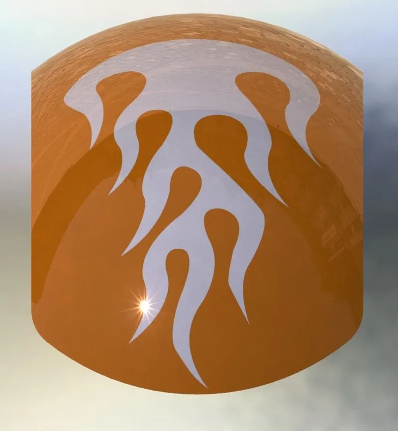 ISOMETRIC AND SIDE VIEWS OF REAR FENDER
FRONT AND REAR WHEELS:
Motorcycle wheel are made to cope with radial and axial forces. Motorcycle wheels are mounted with Breaks, wheel drive arrangement with sprockets and bearings to revolve freely. Traditional motorcycles used wire-spoked wheels with inner tubes and pneumatic tyres. Spoked wheels are usually made of steel and rims are made of steel with aluminium. Now a days cast wheels are using and they are made of aluminium alloy material, but can also made from more exotic materials such as magnesium content alloy or carbon fiber. Usually motorcycle has only rear wheel drive. Because, to pull a object it needs a better grip to pull and while to push the object not only the grips matter. This is why rear wheels are made bigger and wider. Coming to the front wheels these are made smaller for better steering purpose and for equal load distribution.
Design of rear wheel:
In this american chopper rear wheel is mounted with a tyre, caliper and rotor as breaks, spider webbed rim and sprocket. The radius of tyre is 348.65mm and width is 354mm. The tyre is made of rubber material and having holes to provide grip. The diameter of the rim is 510mm having spider web shape. The siper webs are 3 in number and having 120 degrees equal angle. The router of rear wheel having diameter about 320 mm and thickness of router is 7mm. router having holes to provide breaking force along with caliper. Rear wheel also contains a chain sprocket with diameter 300mm and thickness of sprocket is 15mm. The sprocket is designed to have chain transmission containing 60 teeth and value of pitch is 8mm
Design of front wheel:
In this american chopper the front wheel is only mounted with a tyre, rim and router and caliper for breaks. The radius of tyre for front wheel is 393.7mm and width is 154mm. the is made of rubber and provide grips with equal number of spacing. The rim is spider web shaped rim having radius 330 mm and width of the rim is 140mm. There are spider webs are provided in design for every 120 degrees of rotation. 40mm of hole is designed to connect with yoke of fork. The front wheel also have a router and caliper , the diameter of router is 345mm and thickness is 7mm. Router , having holes of diameter 8mm to apply breaks.
FEATURES USED TO DESIGN WHEELS IN SOLIDWORKS:
- Extrude boss/bass
- Fillet
- Chamfer
- Cut extrude
- Revolve
- Circular pattern
- Linear pattern
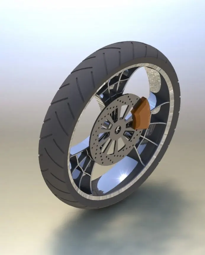
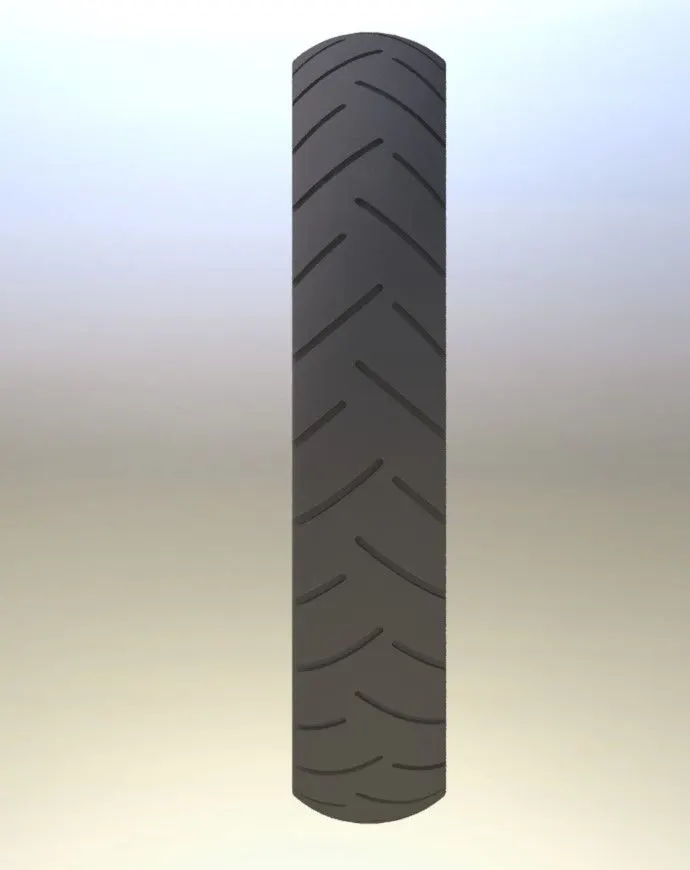
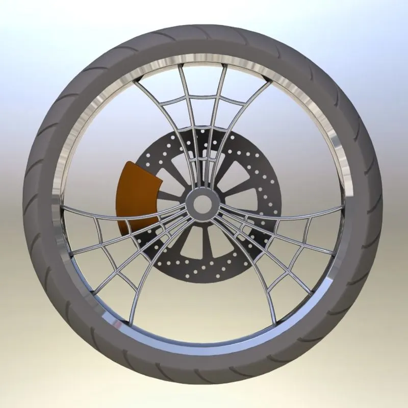
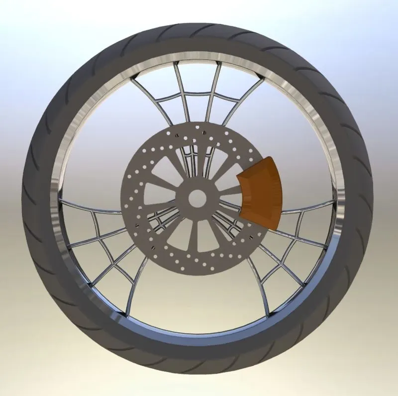
ISOMETRIC AND SIDE VIEWS OF FRONT WHEEL
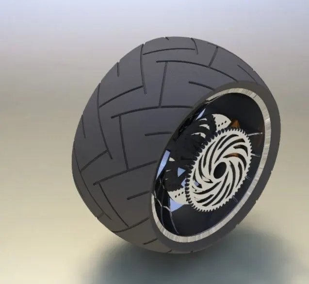
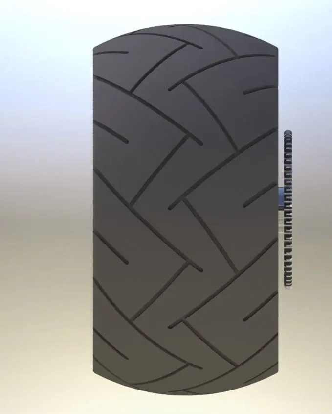
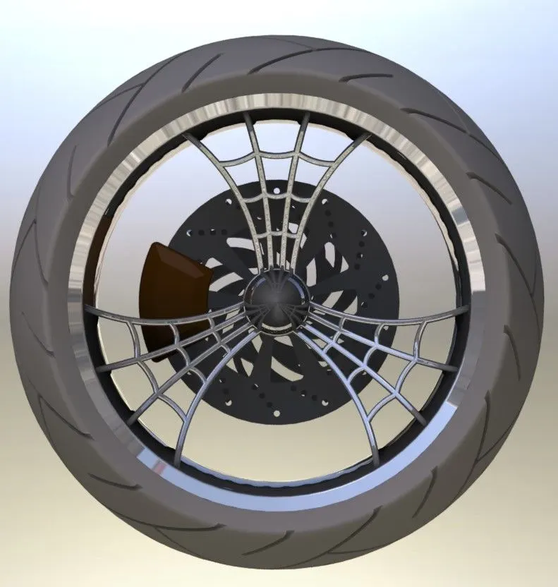
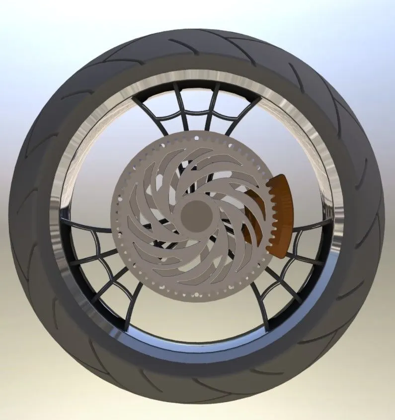
ISOMETRIC AND SIDE VIEWS OF REAR WHEEL
ASSEMBLY OF AMERICAN CHOPPER
In mechanical terminology, assemble is a refers to a unit where all manufactured/designed products are gathered and fix as per the design to make it a single product. Simply, a machine is a device which is combination of several parts to create a motion.
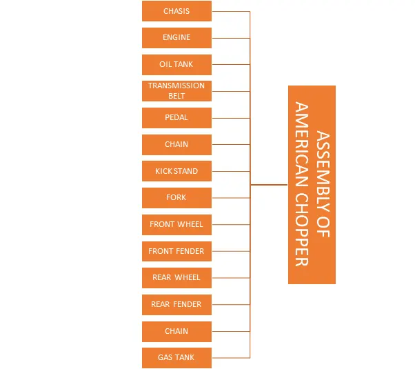
To assemble the american chopper , already designed products is needed to mate it as per the design and to make final american chopper.
The following parts are needed to assemble the american chopper:
- Chasis
- Engine
- Fork
- Oil tank
- Kick stand
- Rear wheel
- Rear fender
- Front wheel
- Front fender
- Chain
- Transmission belt
- Gas tank
FEATURES USED IN ASSEMBLY:
INSERT PART:
Insert part feature is used to insert single or more than one designed components to start assembly.
MATE:
Mate is the feature to create geometric relationships to fix the part with respect to another part. Mates are defined the allowable locations or directions of linear with distance, parallel, makes an angle with other plane and rotational with some limit angle. We can move a part with its degree of freedom by visualizing the assembly behaviour.
ASSEMBLY TREE OF AMERICAN CHOPPER:
ASSEMBLY OF AMERICAN CHOPPER USING SOLID WORKS:
Insert the needed components required foe the assembly of american chopper. Fix the main part(chasis) with respect to the planes povided in the assembly workbench. With the different features available in solidworks like concentric, face mate, parallel mate, etc create the entire assembly od american chopper.
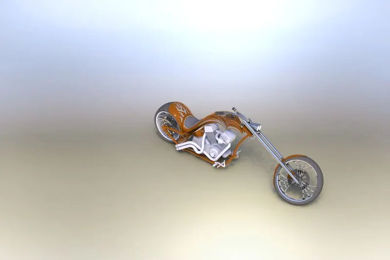
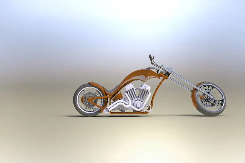
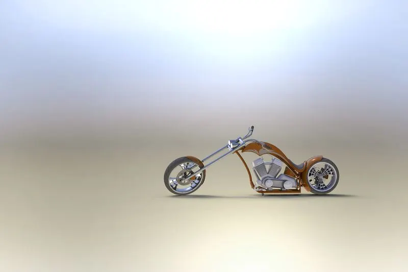
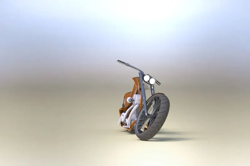
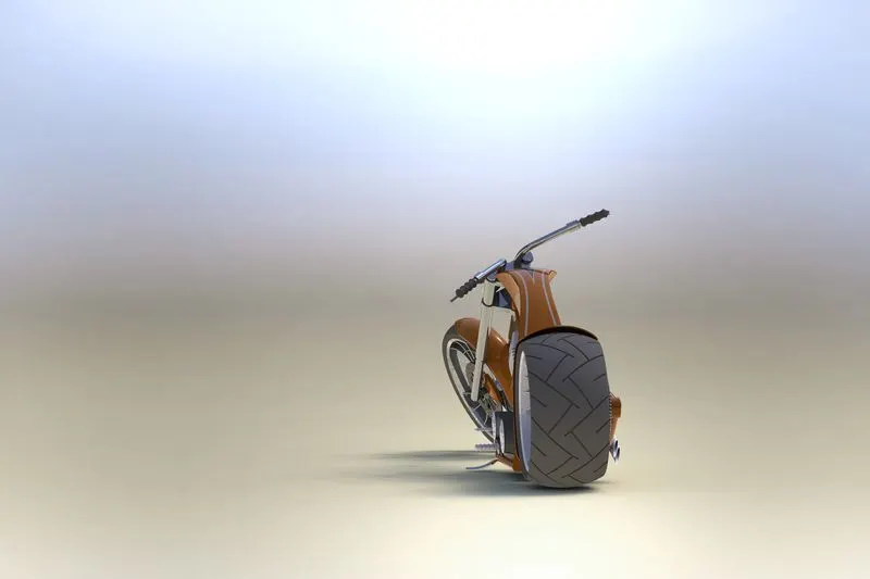
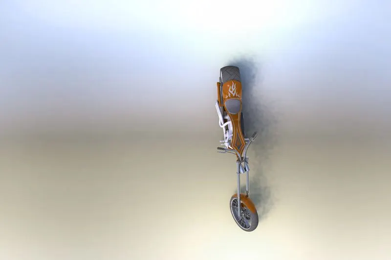
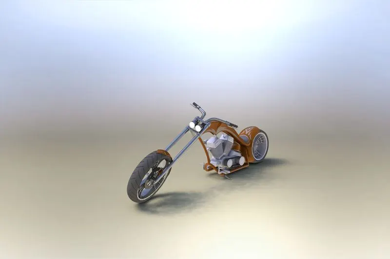
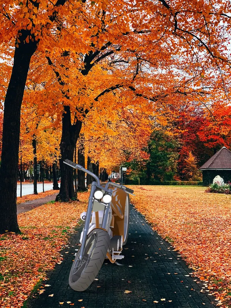
ISOMETRIC, SIDE AND CAMERA VIEWS OF AMERICAN CHOPPER(RENDERED IMAGES)

CONCLUSION:
- Each and every part of american chopper were modeled
- The designed parts are inserted into the assembly environment and american chopper assembly had done.
- The photo-realstic images were rendered by using render tools in solid works and solidworks visualize.