Project 1
Aim : The aim of the project is to Route the Wiring harness on Given Engine and Prepare flatten view drawing in CATIA V5.
Procedure :
procedure for connector creation
- Create/Download 3D connector
- Create required geometrical parameters
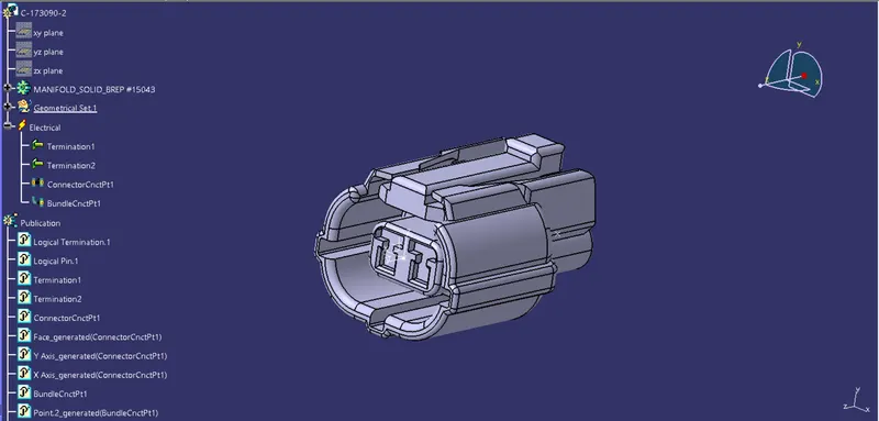
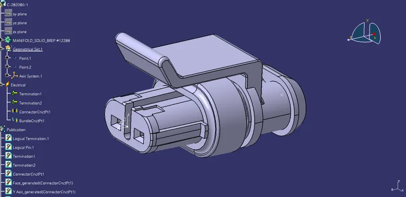
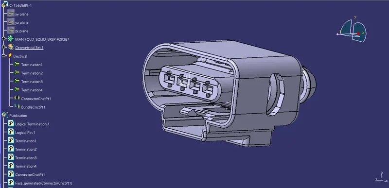
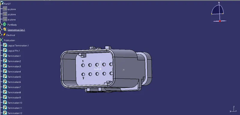
In the reference geometry required reference points like bundling entry point connector connection point and cavity connection points and also the required axis is created in the geometry parameters
- Define part as connector
The parts are defined as connectors by using the define connector option in the CATIA and while defining the connector we give the number of terminals that are there for the connector.
- Define bundle connection point
It is the point that goes on Wire entry side of the connector
- Define connector connection point
It is the point that goes on Mating Face of the connector
C-173090-2
C-282080-1
C-1563689-1
part27
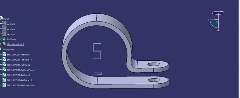
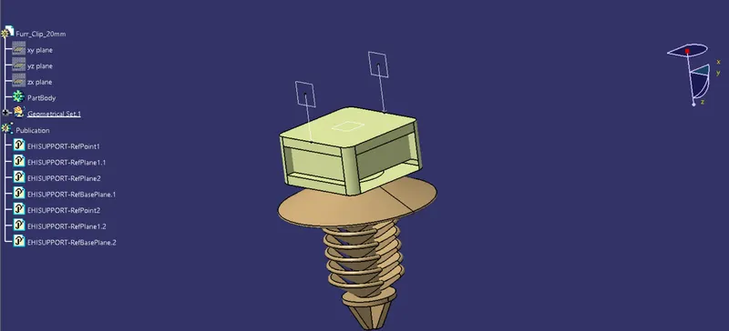
procedure for support creation
- Create/Download 3D connector
- Create required geometrical parameters
In the reference geometry required reference points like entry point,exit point and the planes for entry,exit and the base plane is created in the geometry parameters.
- Define part as support
The parts are defined as support by using the define support option in the CATIA and while defining the part we give the entry and exit point for the part.
p clamp
Furr clip 20mm
Procedure for Creating the Assembly Context and geometrical bundle assembly
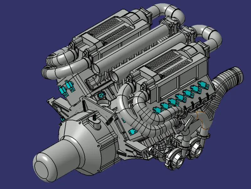
- Add engine product in the context assembly.
- Create engine harness geometrical bundle assembly.
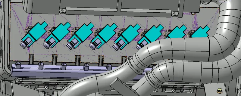
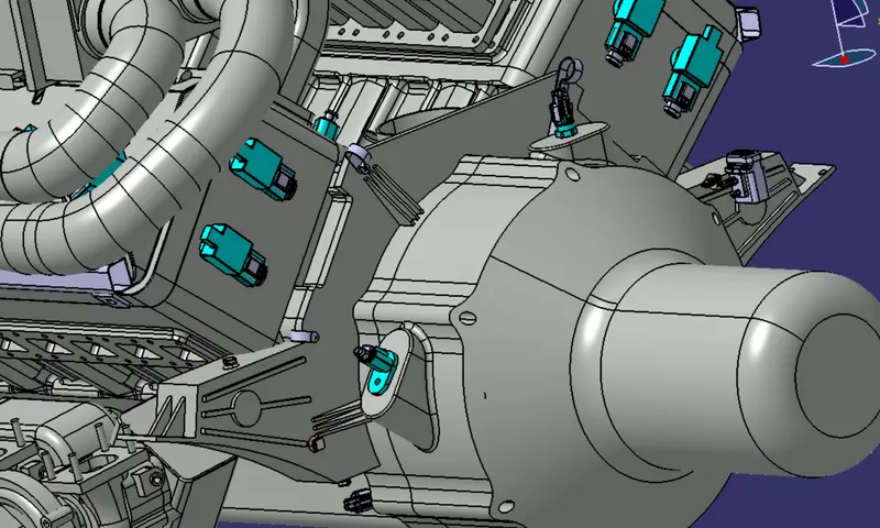
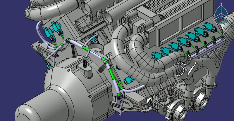
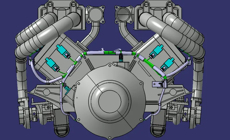
- Position connectors using the manipulation, smart move & Compass on the sockets given in the engine.
- After, that the models are placed in the required position.
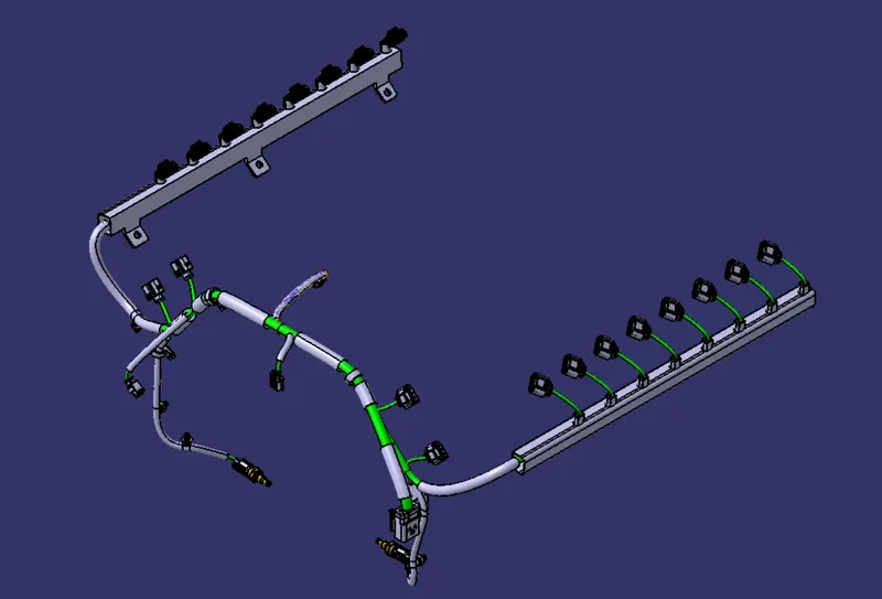
- Once the models are placed in the proper place, the assembly is converted into the geometrical Bundle.
- In the geometrical Bundle, the multi Branchables are created.
- By using the bundle definition and then the bundle segment point the bundles in the required places are created.
Procedure for Creating the Flattening
- Create a product file and open Eletrical Harness flattening workbench.
- click on flattening parametres feature and fill the details.
- Next select the extract option and select the assembly harness bundle that we created in the week 4 challenge.
- The wire harness assembly is imported to the Wire flattening product file with 'EHF' extension added to the geometric bundle assembly name.
- Next select the flatten option and select the desired plane to flatten the wiring harness bundle.
- Next select the rotate option and orient the wiring harness bundle as per the given layout.
- Next save the product file using the save management.
- Create a new drawing file and save the file in the same location.
- Add the front view of the harness assembly by selecting any one of the flat faces of the connector and orient the view as per the requirement.
- Go to the properties of the view and select the '3D Wireframe' on and ' Is always visible' option in order to see properly the Wire bundle, connectors and the protection coverings.
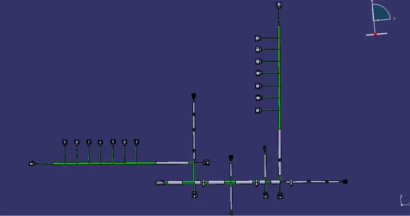
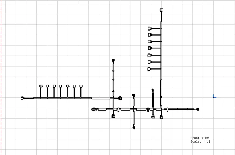
Conclusion :
The Routing is created for the given model by using the different workbenches in CATIA like Part Design, Assembly Design. Electrical Part design, Electrical Harness Assembly, etc.