Week 8 - Challenge 3 - Switch Bezel Design
Report
Here firt we discuss how we created a tooling axis.
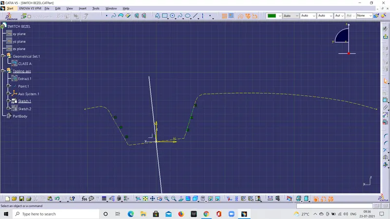
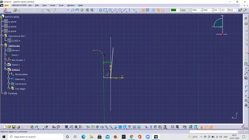
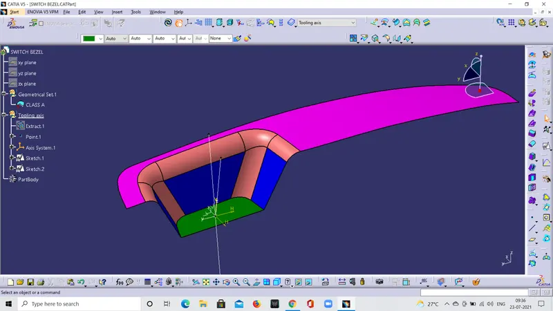
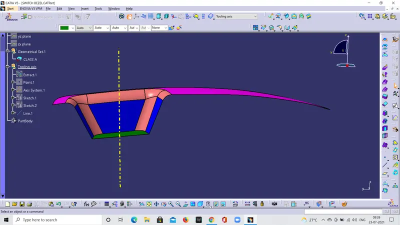
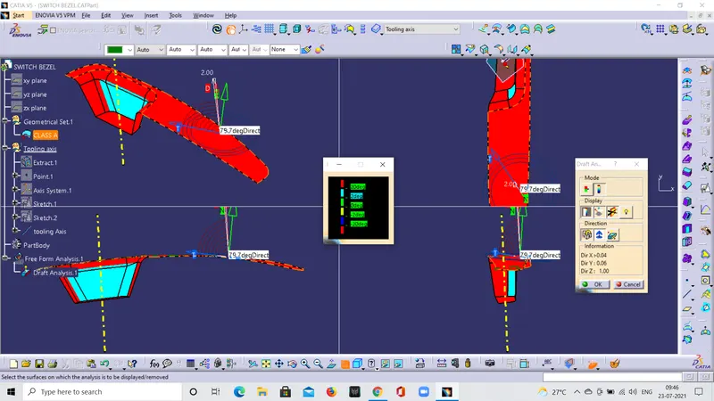
First we extracted the base of the switch bezel and make a center point for that base, axis is added for the base at the center point. After creation of axis we create a position sketch at xy plain to of the axis in the sketch we draw two lines along the side walls by the tool intersect the 3D element .After drawn the two lines we can get a bisecting line for the two wall lines. This is one of the dummy tooling axis of the xy plan and again we drawn the position sketch along the yz plan for the axis . we draw the line along the wall and get the another dummy tooling axis of yz plan from the point 1 at an angle of 5 degree from the wall plan . By this two dummy tooling axis of xy and yz plan we get a bisecting line .This line is TOOLING AXIS for the switch bezel panal.
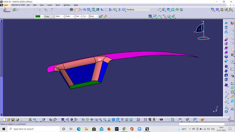
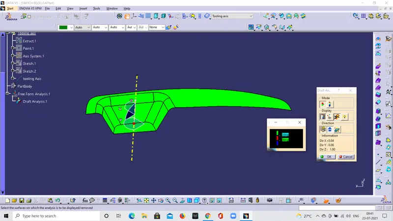
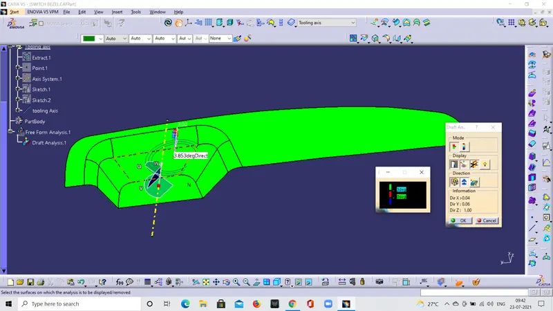
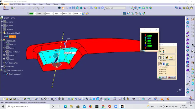
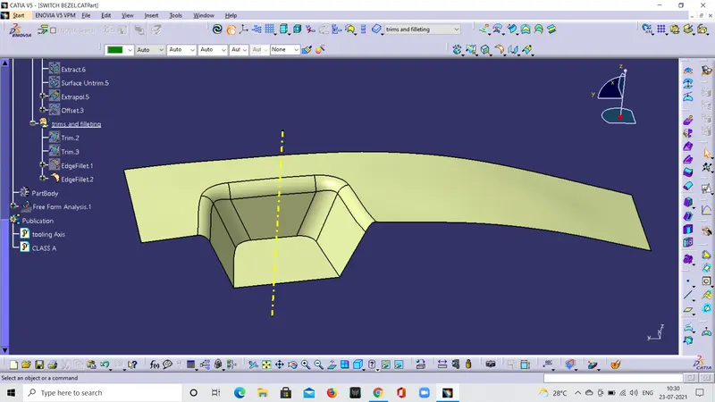
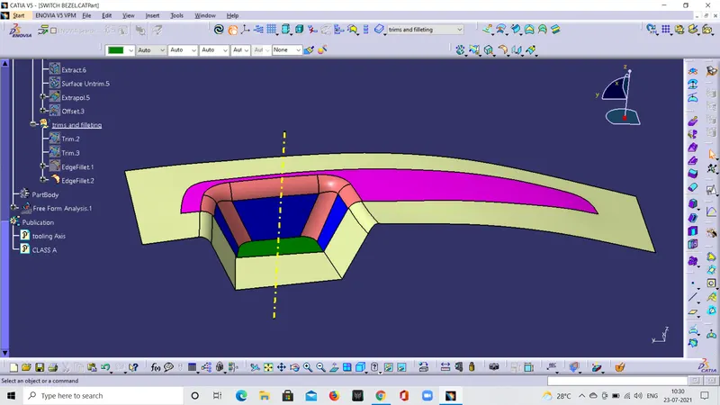
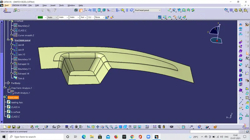
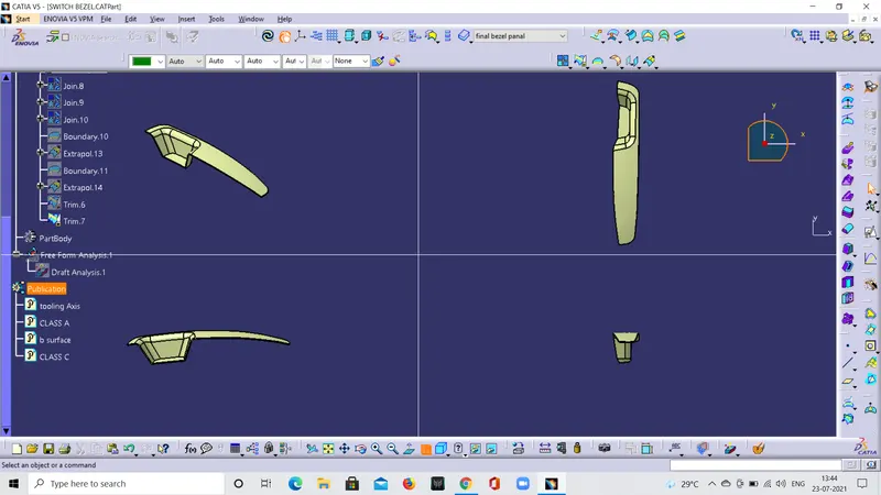
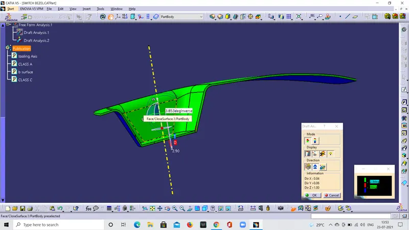
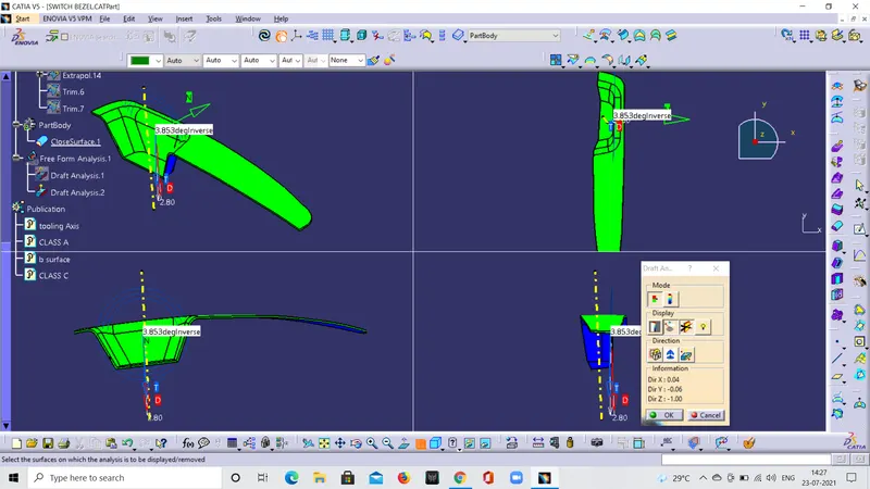
After getting the tooling axis we have done draft analysis on the CLASS A surface of the switch bezel and got green colour in the surface. we have given that more than 3 degree it should be in green colour and less than 3 degree is red colour and the -ve value is blue colour . But we get the entire surface is in green colour that means the surface is more than 3 degree . we had also done full mode analysis for the surface and got different colours at different degree of angle according to the angles and colours given in the table for out requirement.
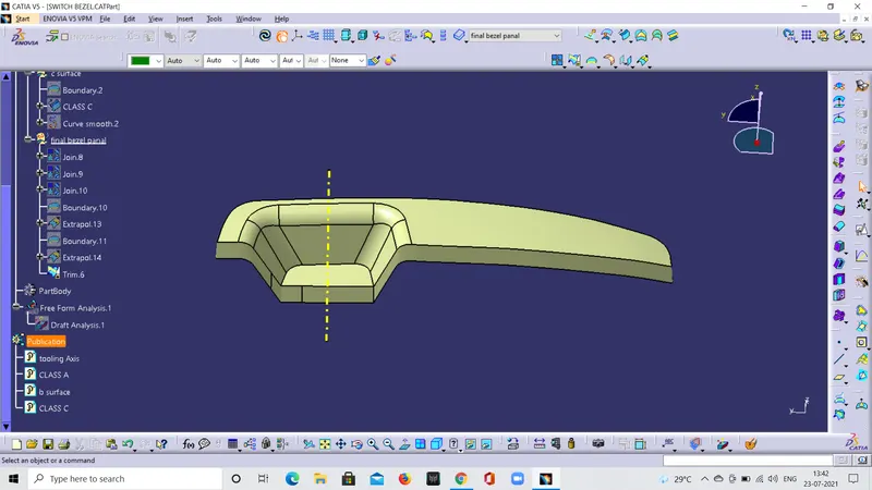
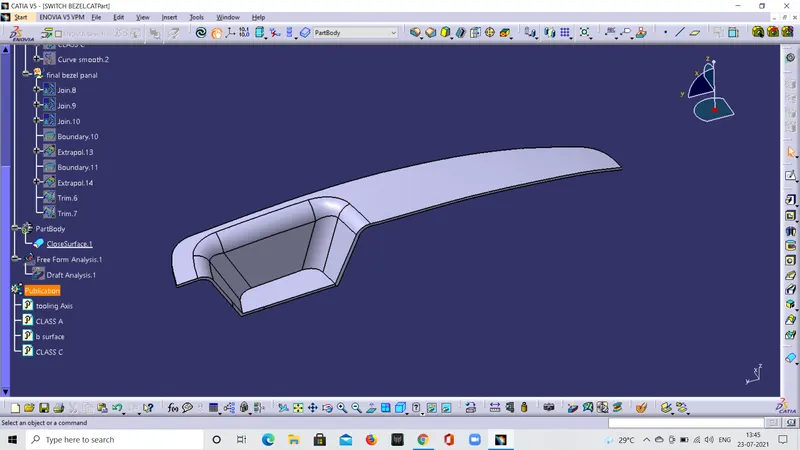
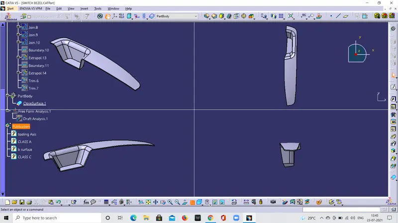
After getting the required results from the draft analysis we publishesd the tooling axis and the class A surface. After that we created the class B and class C surfaces and also published that surfaces. After that we got the final closed switch bezel and this closed switch bezel is converted to solid in the part workbench.
This solid swetch bezel is again done draft analysis in this draft analysis we got the results that is the surface is in green colour .we have given that more than 3 degree it should be in green colour and less than 3 degree is red colour and the -ve value is blue colour . But we get the entire surface is in green colour that means the surface is more than 3 degrees and the side draft wall that we are drawn has got 2.97 degree that means it is also almost 3 degree.
so in this way we had got the tooling axis and the draft analysis for the class A surface and the solid surface.