Week 8 - Challenge 4 - Coin Holder Design
Aim:- The Aim of the project is to create a solid model of the given class A surface of the Coin Holder by applying the design rules.
Objective:-
- To create a tooling axis on the class A surface so that we can perform the draft analysis on class A surface and the solid part.
- To create the class B and class C surface using the class A surface.
- To get the final solid closed body from all the surfaces.
- we need to plublish the class A, class B , class C , Final solid body and the tooling axis.
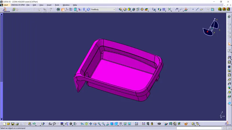
Given Coin Holder class A surface.
Tooling Axis:-
Here first we will discuss how the tooling axis is created for the give class A surface.
- In the given class A surface the side walls are perpendicular to the base so it will create a problem while open and close of mold.
- so we need to tell the class A surface designer to give some draft angle to the all plains, so that it will not create any problem while manufacturing.
- In the surface the wall are perpendicular so we extracted the base and kept the point at the center of surface.
- At the center point we drawn the line with normalto the surface.
- The line drawn along the center point is the TOOLING AXIS of the surface.
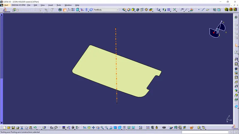
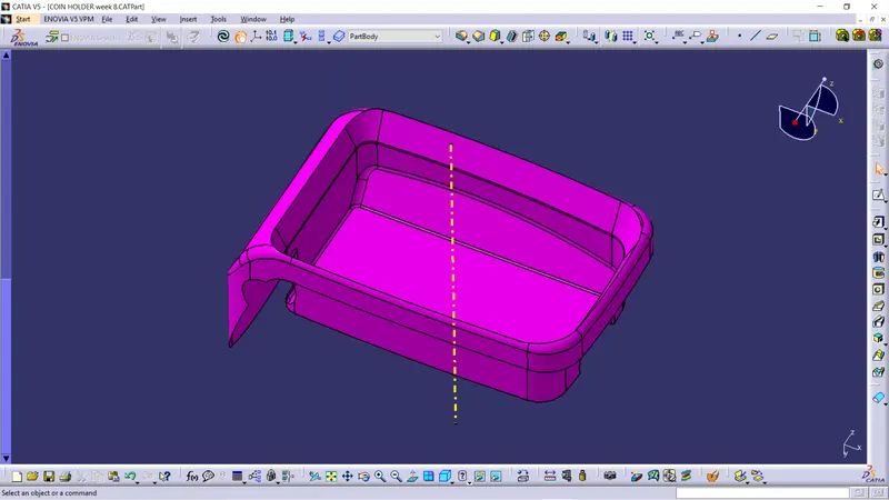
Tooling axis of the class A surface
Draft Analysis along the Tooling Axis on class A surface:-
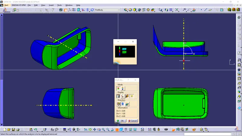
- Draft analysis was performend on the class A surface along the tooling axis to analyse if the given component is toolabe along the tooling dircetion.
- Feature draft analysis option is used to perform the draft analysis on the surface.
- Compass is placed on the created tooling axis using the option in draft analysis ,next the surface is chosen to perform the draft analysis.
- We take maximum of 3 degree of draft angle for the surface.
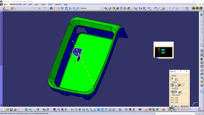
Here we can see the side walls are less tha 0 degree that is because the side wall are perpendicular to the base.
B Surface creation :-
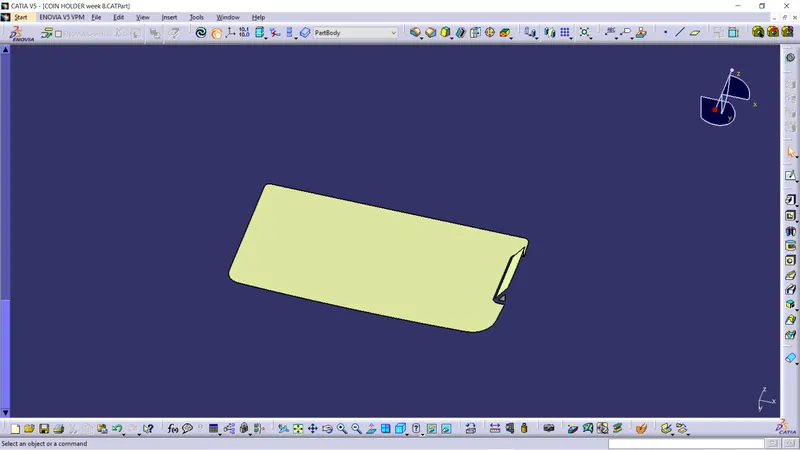
In creation of B surface we divide the class A surface in different geometrical parts and at last we trim and join all together and made B surface.
side walls
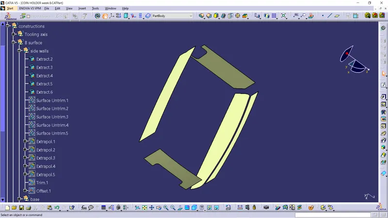
Here we extracted the side wall of coin holder.
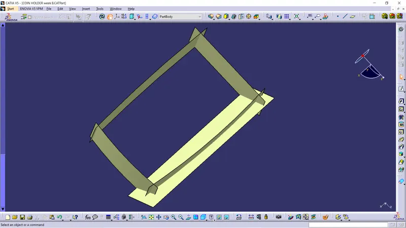
After extracting the side walls we untrim the surfaces and extrapolate the surfaces.
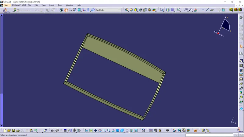
After extrapolate we trim the wall and offset the walls at 2.5mm.
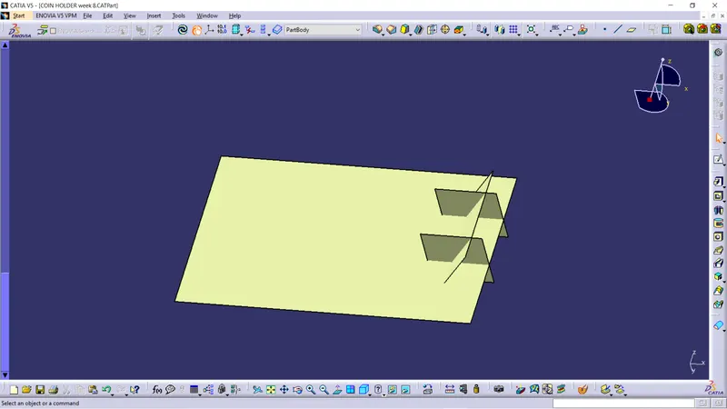
Base
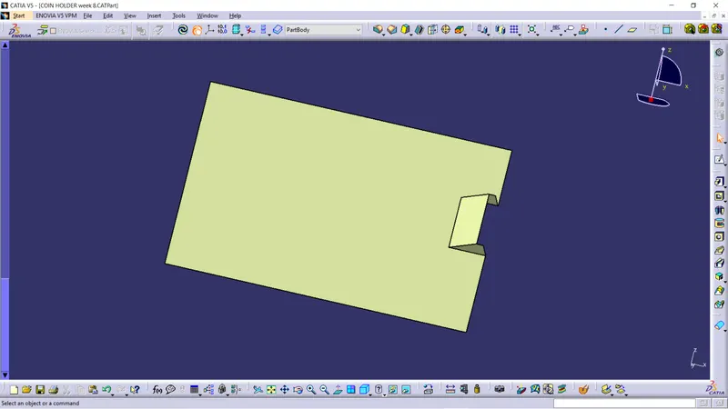
Next we do the same process for all the plains and surfaces as we did for the side walls
Top walls
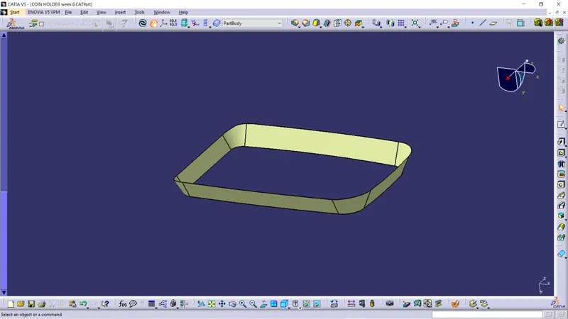
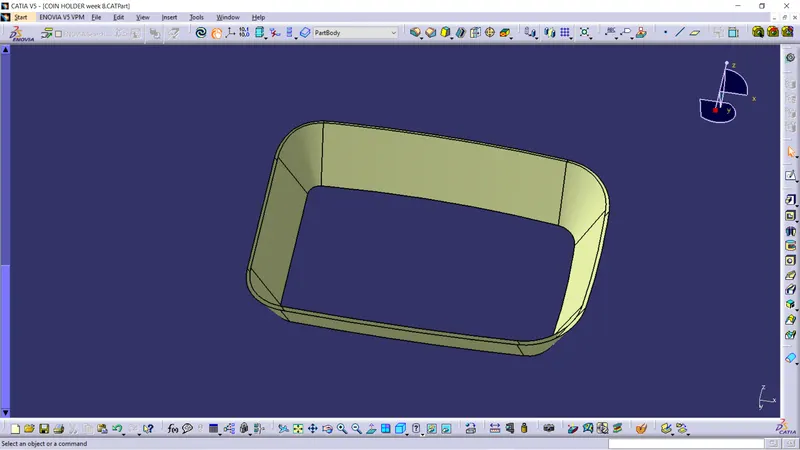
Initial trim and fillet
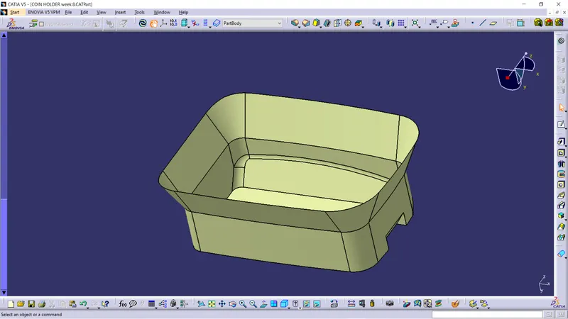
Outer flange
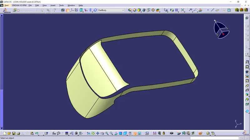
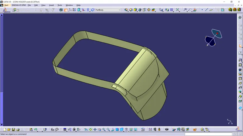
Final trim and filleting
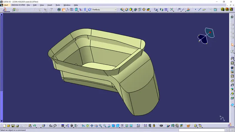
After trimming we do filleting at the sharp edges.
The fillet is given to the B surface according to the which side class A surface.
If the B surface is inside the A surface the fillet should be given as the outer fillet radius of class A - Thickness or distance between the both the surfaces.
If the B surface is outside the A surface the fillet should be given as the outer fillet radius of class A + Thickness or distance between the both the surfaces.
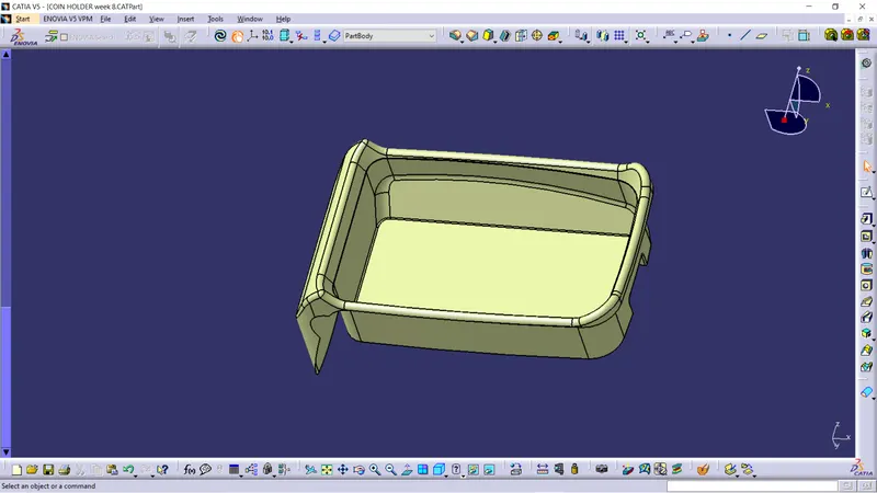
This is the final B surface which we get from class A surface.
C Surface creation :-
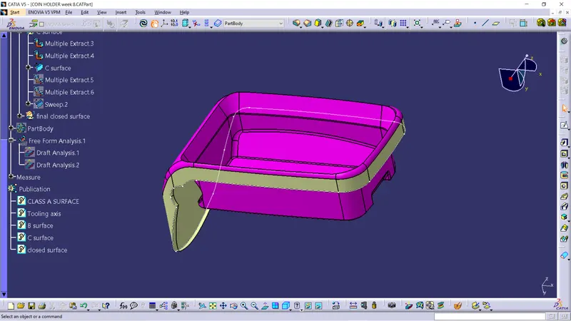
In the creation of C surface we multiple extracted the boundary line and the outer flange and we sweep the boundary line with reference surface at 90 degree inside the class A surface.
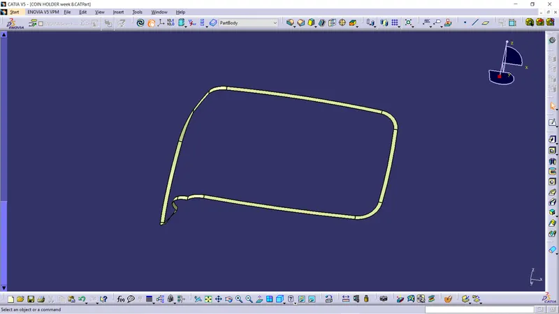
This is the final class C surface of the coin holder.
Final closed surface:-
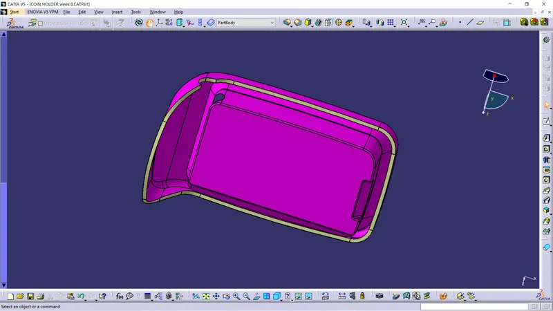
In the closed surface first we joined the class A surface abd the class C surface together.
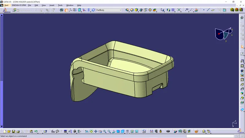
After joining the class A and class C surface we trim the joined surface with class B surface and we will get the final closed surface of coin holder.
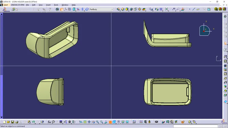
Different view of the closed coin holder surface.
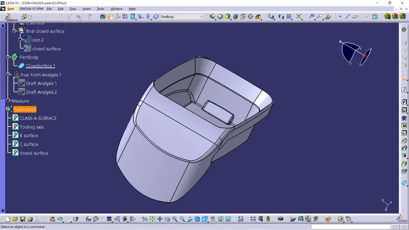
This is the closed solid part coin holder.
Draft analysis on solid enclosed body:-
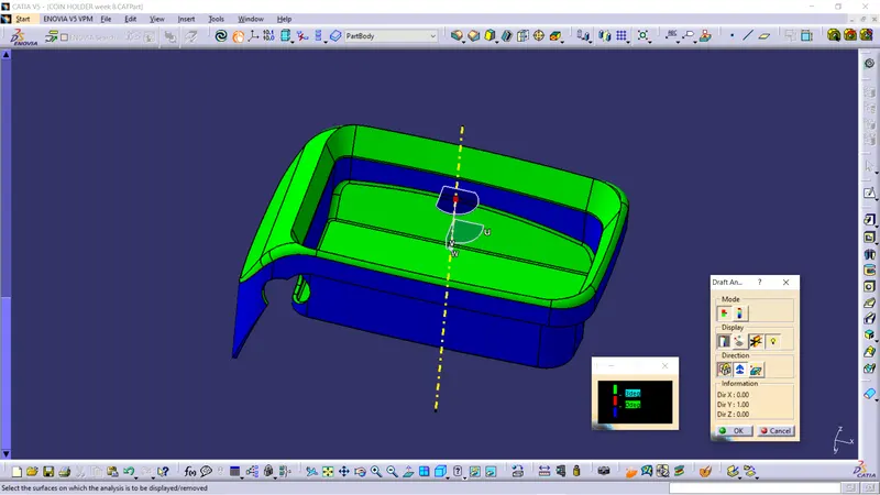
- Draft analysis was performend on the solid enclosed body along the tooling axis to analyse if the given component is toolabe along the tooling direction.
- Feature draft analysis option is used to perform the draft analysis on the solid enclosed body.
- Compass is placed on the created tooling axis using the option in draft analysis ,next the solid enclosed body is chosen to perform the draft analysis.
- We take maximum of 3 degree of draft angle for the surface.
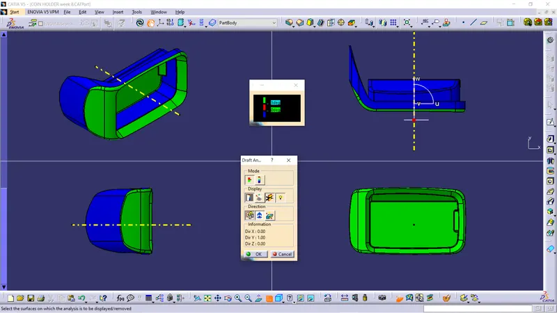
Different views of Coin Holder when draft analysis is performed along tooling axis.
Conclusion:-
- The Door arm rest component is created using class A surface.
- The tooling axis are created on the class A surface and performed the draft analysis on class A surface and the solid part.
- The class B and class C surface are created using the class A surface.
- The class A, class B, class C, Final solid body and the tooling axis are published.