Week 8 - Challenge 5 - Core & Cavity Design
Aim:- The Aim of the project is to create a core and cavity block of switch bezel.
Objective:-
- To create a tooling axis on the class A surface so that we can perform the draft analysis on class A surface and the solid part.
- To get the final solid closed body for Core and cavity blocks.
- we need to plublish the, Tooling Axis,Parting Line and Parting Surface.
Tooling Axis:-
Here first we will discuss how the tooling axis is created for the give class A surface.
- First we created a dummy tooling axis by extracting the base surface and created a center point for that base and add axis to the point and drawn a line through the point along the z direction.
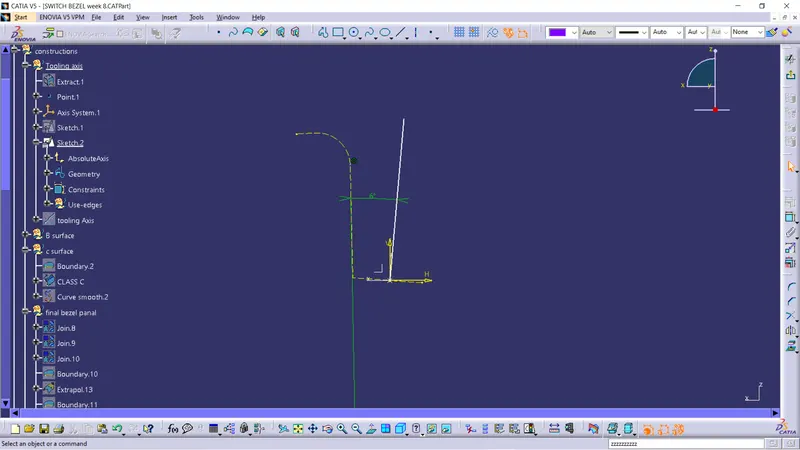
- Next we drawn the sketch for the class A surface along the yz axis and drawn the lines along the two side plains and drawn the bisecting line from the two side plain lines using the center point of base plain.
- The bisecting line which we got from the yz axis two side plain is the Tooling clearing y axis lines.
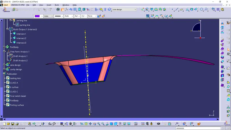
- Next we drawn the sketch for the class A surface along the zx axis and drawn the line along the side plain and drawn a line 6 degree from side plain line from the center point of base plain.
- The 6 degree line drawn using the side plain is the Tooling clearing x axis lines.
- By using this two tooling clearing axis lines we can get the bisecting line from the center point on the base plain.
- The bisecting lines is known as the TOOLING AXIS of the class A surface.
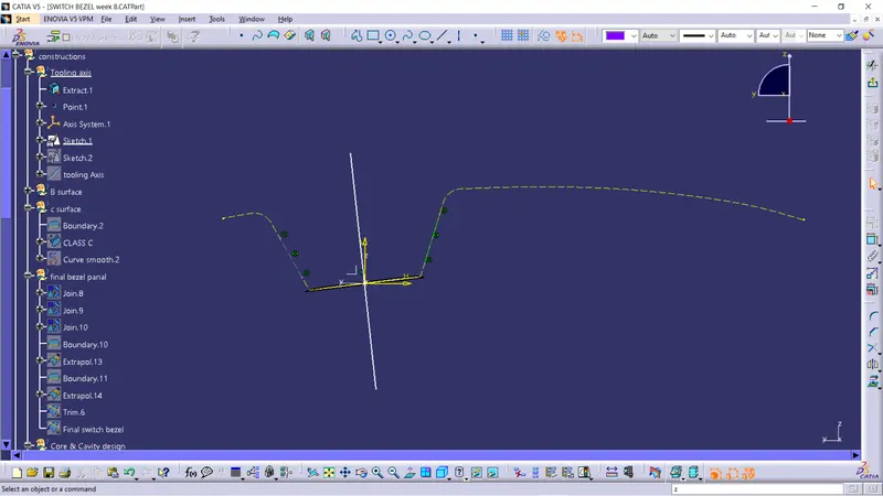
Tooling clearing axis in y direction
Tooling clearing axis in x direction
Tooling axis of the class A surface
Draft Analysis along the Tooling Axis :-
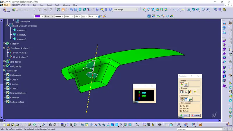
- Draft analysis was performend on the class A surface along the tooling axis to analyse if the given component is toolabe along the tooling dircetion.
- Feature draft analysis option is used to perform the draft analysis on the surface.
- Compass is placed on the created tooling axis using the option in draft analysis ,next the surface is chosen to perform the draft analysis.
- We take maximum of 3 degree of draft angle for the surface.
Core and Cavity block design :-
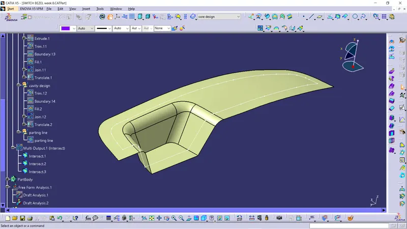
Here we kept the boundary for class A surface and extrapolate the boundary with class A surface.
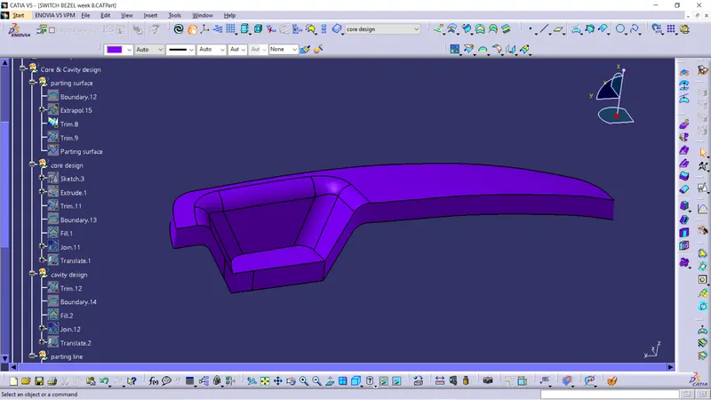
we trimed the extrapolated class A surface with class c surface
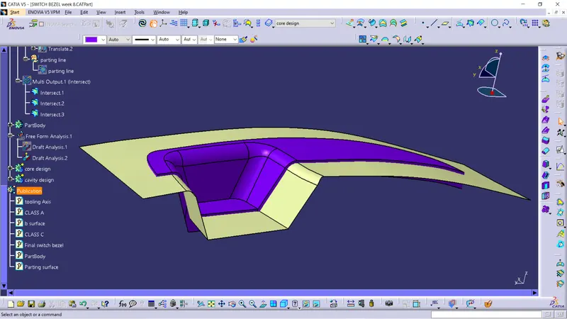
Now we trimmed it with the class B surface.
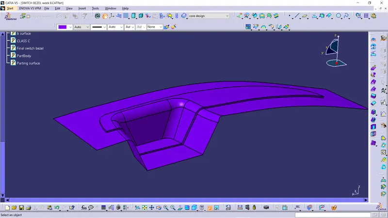
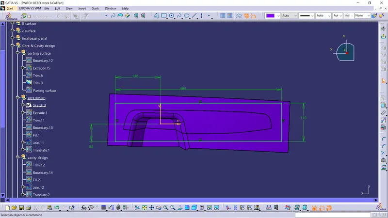
we drawn a rectangular sketch in xy plan.
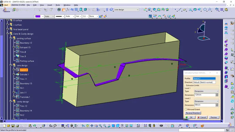
we extruded the rectangular sketch.
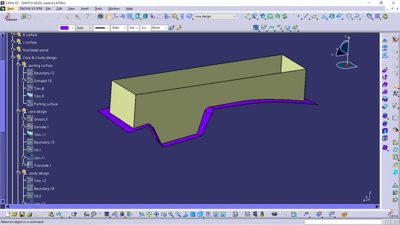
After extruded the sketch we trimmed it with surface at core side. And we filled the upper surface and joined the filled surface and core side
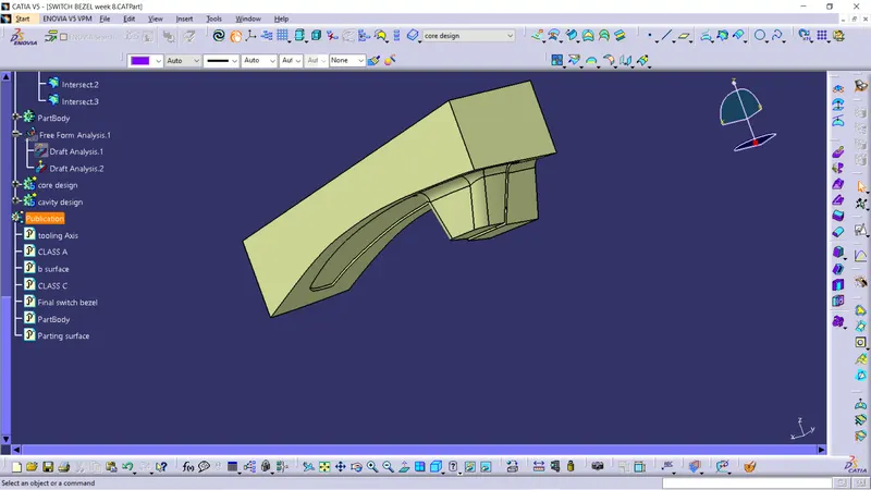
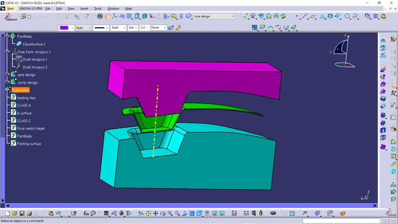
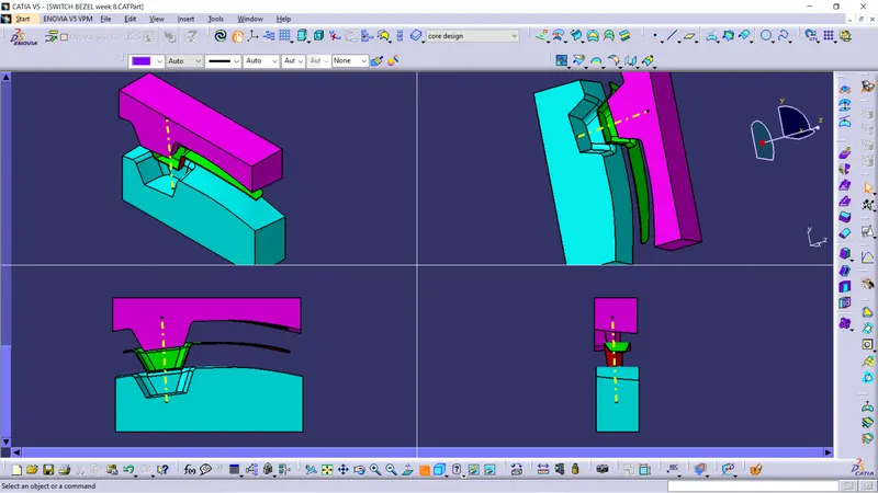
This is the final closed core side.
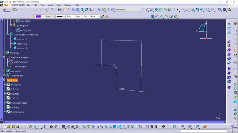
Here we can check that we got everthing properly or not by intersection tool.
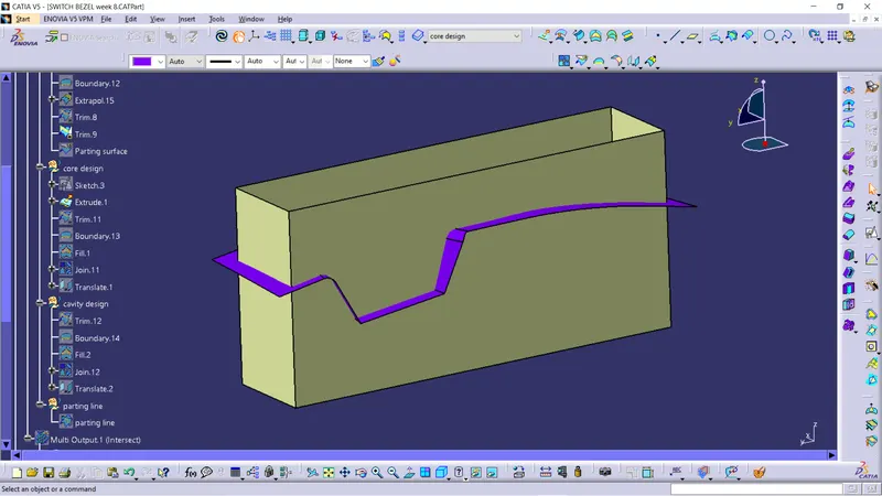
For cavity side we take the class B surface and extruded surface and we trim both at cavity side.
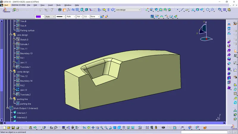
After trimming we filled the lower surface and joined the filled surface and cavity side and we get the final closed cavity side.
Parting line :-
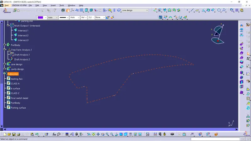
The parting line is the region which marks the border between the inside and outside of the part.
Parting surface :-
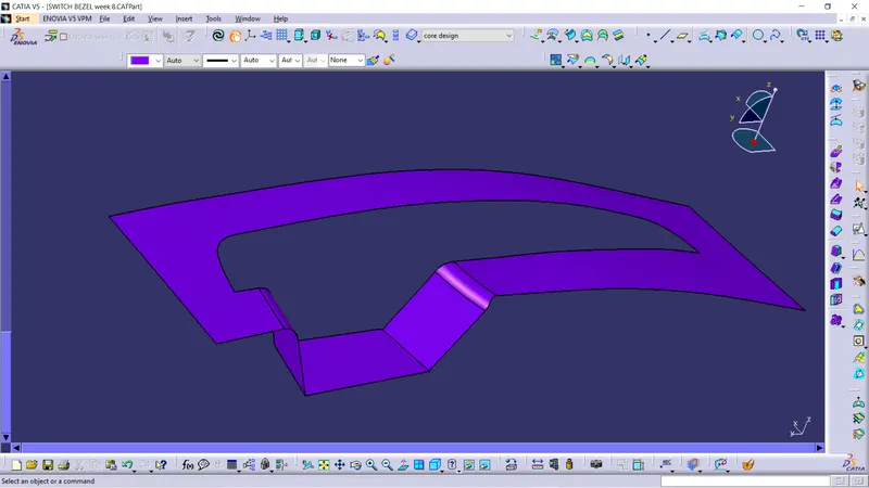
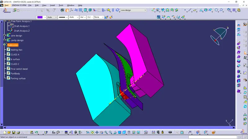
Parting surfaces are used to separate the cavity from the core. Creating a Parting Surface surface, which is extruded from parting lines, to separate the cavity from the core.
Final Core & Cavity Design :-