Project 1
Aim:
To make a harness for given engine by using Catia.
Procedure:
1.download the required Engine,connectors, clips and clamp files and save those file as cat part.
2.Define the connector P-clamp and bottom channel as electrical by using Electrical part design work bench.
3.To define connector as electrically we need add point for.bundle entry point and point then create an axis system in connector connection point part design workbench
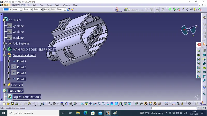
Once geometric parameters added we need to change the workbench to electrical part design workbench.
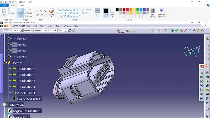
Their we need to define connector electricaly by using define connector their one dialog box appeear we need to give connector type, number of terminals and click Ok.o
Then we need to define bundle connection point for that click on define bunxle connection point command, then one dialog box appear on that we need select the reperensative face point and intial contact by doing this the bundle entry point.
Define connector connection point for the we need select define connector connection point command and select the connector and one dialog box appear their we need to select represetation as pointand select the contact as face then orientation as X axis and coincidence as Y axis click ok then connector connection point is define and click ok save the file.
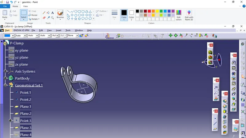
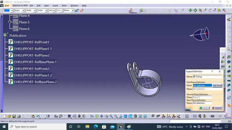
3.Define P-clamp we need create points and plane for that we define the clam twice because this clamp or frr tree clip their the bundle can entry and exist both side so we need to define twice , to define P clamp we need to use the command SUPPORT and define it electricaly
 .
.
4.Define Guiding Channel
In part design work bench we need create point between the channel entry and closed side and then create one center line by using point to point method.
After that we need to give eight point with respect to channel for bundle entry then switch the workbench from part design to Electrical part design workbench.
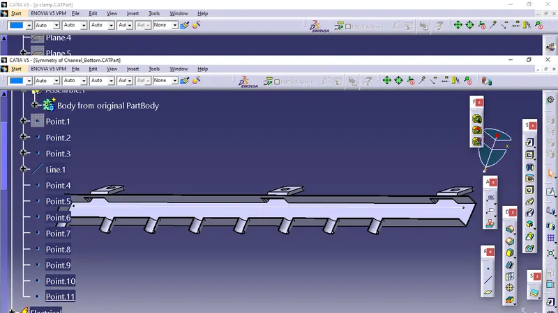
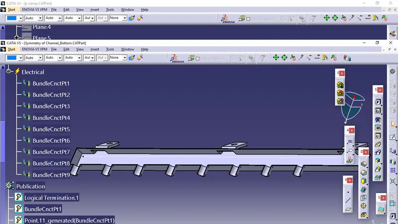
Theier we need to define channel as mounting equipment and define the bundle entry point then save the file.
4.Engine Context Assembly
The first thing we need to open assembly workbench and make the product as Context assembly then and add existing Engine part file then create create a new product and change name into Geometrical bundle assembly this two product that is engine part fileband geometric product file should comes under The main Context assembly.
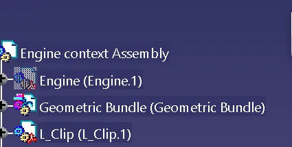
We have position the connectors pclam into the given engine make sure that connectors and pclamp are come inside the geometric bundle.
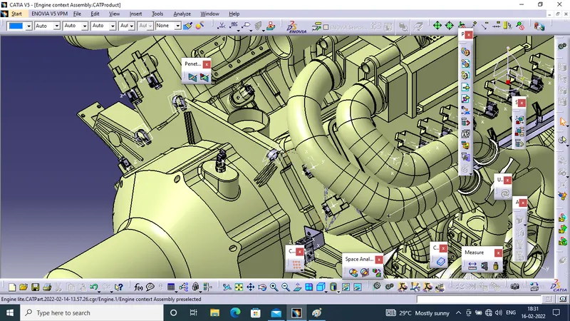
The connector and pclam are position in its location by using manipulation and snap commands.
Once this placed in respective position we can start the routing.
5.Multi branchable
To start the routing we need click on the multi branchable command in harness assembly work bench and the multi branchable product file create in specification tree automatically
We need to give the bundle diameter, bend radius as 1.5 in the ratio select the routing definition their we need to select intersection connector first then select the p clamp one by one
For bottom channel we select the option called external curve and join this with main branch.
6.Addind branch point
Inorder to create sub branch we need to use the command ADD BRANCH POINT then select on the bundle and create were we want
Once again click on multi branch then give the bundle dia bend radius then route definition select on bundle and then to the connector check the tangency then the bundle is created click ok.
For channel create the branch point then in route definition select the branch point then select the channel again in route difinition this time select from channel to connector check the tangency click on ok.
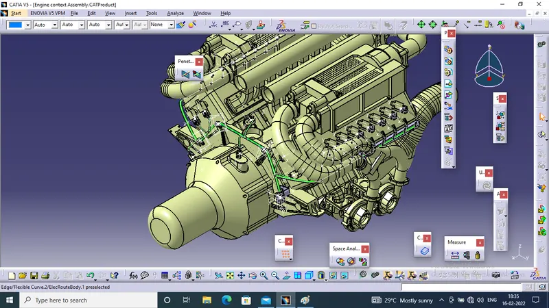
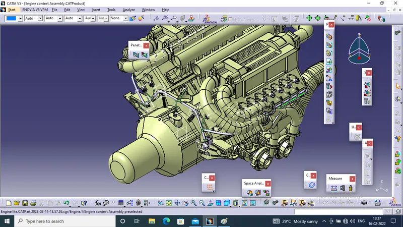
Save As the file by using save management and save over the respective files.
7.Flattering
For flaterning first thing is we create new product and change the name into engine flatterning then give parameters.
In paramer dialog box we have check the parameter which require as our needs click ok.
Then all the commands get ative their we need to select the extract command. by click that cammand swich file to geometric file in catia. Then select the geometric bunddke assembly in specification tree.
By clicking this the geometric bundle file is imported into flattering workbench.Then click on flattering command one dialogue box appear their select the active plane in channel face and select the bundle and select the Select All Bundle option then click on ok
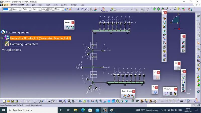
So the harness get flattern then we can rotate the bundle as our requirements and snap were necessary.
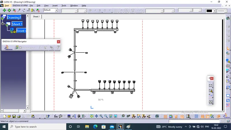
8.Drafting
After faltern import the flatern file into drafting by using fornt view and select face in the bottom channel. Once the file imported we need go to property of work view active the 3D wireframe click ok.