Project 1
ans).Need of state flow
Stateflow provides a graphical language that includes state transition diagrams, flow charts, state transition tables, and truth tables. You can use Stateflow to describe how MATLAB algorithms and Simulink models react to input signals, events, and time-based conditions. Stateflow enables you to design and develop supervisory control, task scheduling, fault management, communication protocols, user interfaces, and hybrid systems. With Stateflow, you model combinatorial and sequential decision logic that can be simulated as a block within a Simulink model or executed as an object in MATLAB. Graphical animation enables you to analyze and debug your logic while it is executing. Edit-time and run-time checks ensure design consistency and completeness before implementation
In this project a flow chart has been mentioned which provides us a condition of fuel usage strategy as per the power demand increases or decreases.for implementing this condition in state flow following chart was prepared :
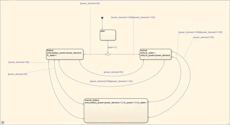
the state flow starts with start which is connected to an input constant when constant is provided with "1" the simulation begins at that instant
next it comes to decision making point where if the power demand is <minfuel cell power = output fuel source is selected if yes the then fcs is kept on standby and battery is used as main source
if the power demand is larger than min fc power then use fuelcell stack as source next it again evaluates if the power demansd is >maximum fuelcell power : if yes then the source will be used as battery if not then again it will jump back to using fuel cell stack as main source :
the following implementation of flow chart can be observed with output result:
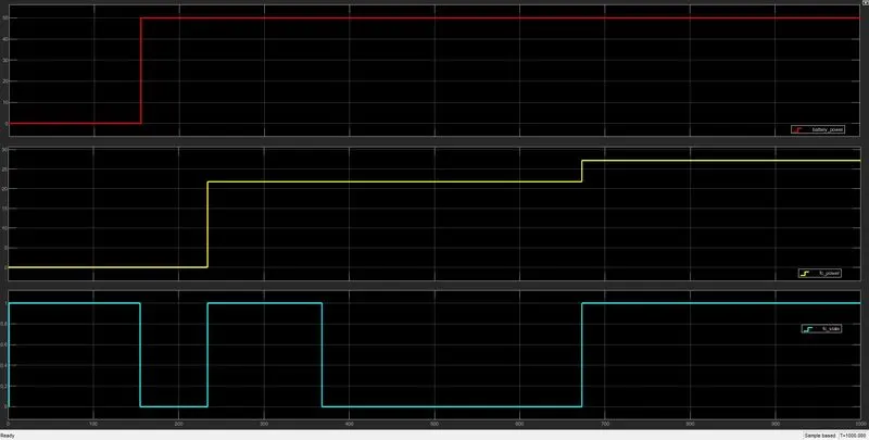
the graph in:
"red":represents the battery power
"yellow":represents the fuel cell power
"blue":represents FC Operating state
the power demand was provided throug the signal builder block as follows:
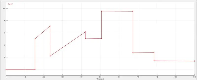
We will use stateflow and simulink to meet the required logic
- Signal builder is used to create a power demand profile.
- Sateflow has all the required logicbuilt within itself.
- Finally the scope used to capture the output of stateflow logic
According to the power demand profile the transition between states will take place.
Power flow logic here implements the logic. This logic if said theoritically simply means that fuel cell will supply power to the motor when the power demand is >=50 and 100<=. Battery has its role when the power demand is 50< and when the power demand is >=100 where battery and FC both supplies the power to the motor.
Finally the three outputs from power flow logic are FC operating state which shows the active and inactice sate of fuel cell. Fuel cell power tells how much is the power being provided by FC to the motor and same applies to Battery power.