Project 2 Thermal modeling of battery pack
The Lithium-ion batteries are widely used as energy sources in different hybrid and electric vehicle, however, the operation characteristics of the battery in such vehicle are strongly dependent on the operation temperature and therefore, with purpose to improve these characteristics a good thermal control system should be utilized.
The temperature of a Lithium battery cell is important for its performance, efficiency, safety, and capacity and is influenced by the environmental temperature and by the charging and discharging process itself. Therefore, a thermal model of the battery is used in order to calculate and estimate the cell temperature.
So, for 10-cell series lithium ion battery here I used MATLAB Simulink for finding thermal effect and life cycle performance related to temperature, change
Thermal Behaviour and Fault setup
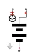
For cell 01 to 04
- Number of series-connected cells are 4
- Initial Temperature is 299.1 K
For cell 05 (faulty cell) changes in Electrical system of cell were made so that we can see the fault observation.
- Number of series-connected cells are 1
- Initial Temperature is 299.1 K
- Capacity (A*hr) = Capacity_LUT*0.80
- Em open-circuit voltage (volts) = Em_LUT*0.7
- R0 terminal resistance (ohms) = R0_LUT*3
- R1 cell resistance (ohms) = R1_LUT*4
- C1 capacitance (farads) = C1_LUT*0.70
For cell 06 to 10
- Number of series-connected cells are 5
- Initial Temperature is 299.1 K
- Temperature Source: This block represents an ideal energy source in a thermal network that can maintain a constant absolute temperature at the port regardless of the heat flow rate.
temperature is set at 299.1 K or 25.95 C.

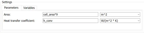
- Convective Heat Transfer: This block models heat transfer in a thermal network by convection due to fluid motion. The rate of heat transfer is proportional to the temperature difference, heat transfer coefficient, and surface area in contact with the fluid 3 blocks for convection are provided
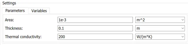
- Conductive Heat Transfer: This block models heat transfer in a thermal network by conduction through a layer of material. The rate of heat transfer is governed by Fourier's law and is proportional to the temperature difference, material thermal conductivity, area normal to the heat flow direction, and inversely proportional to the layer thickness.
The conduction is done from the 2 set of blocks, 1 block is used for 01-04 and other is used for cell 06-10.

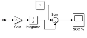
For SOC calculation here Gain block , Integrator and Sum block with PS simulink convertor is provided.
Observation:
the test were performed as per below sequence and with following data:
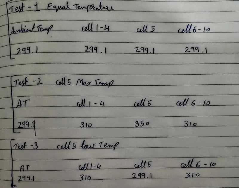
test 1). cell 5 temp equal to other cell temp.
in this test the cell temp is kept equal to the temperature of other cells (1-4, 6-10)
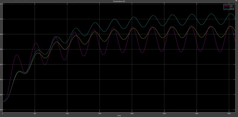
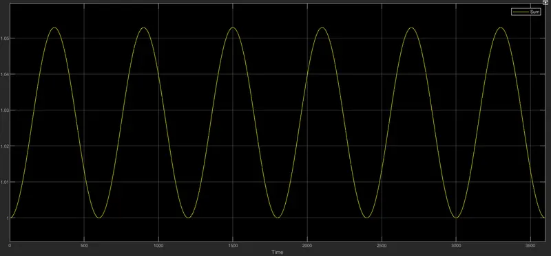
state of charge :
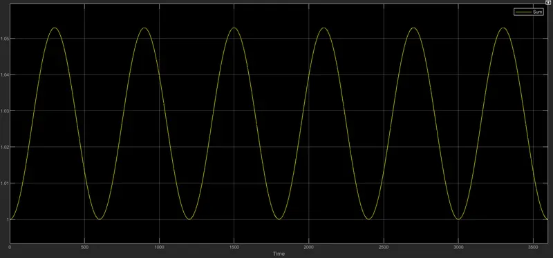
as from the result obtained from the scope we can observe that battery is fluctuating whichtotally depends upon the charge and discharge characteristic in addition to the temperature of battery .
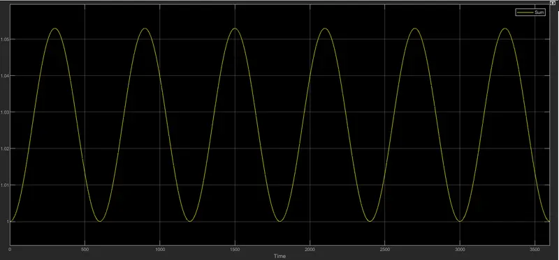
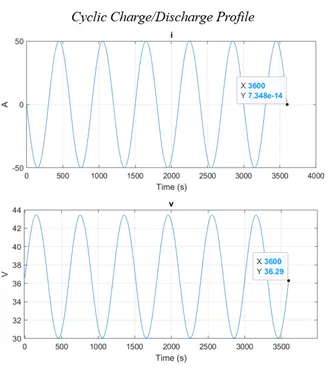
charge and discharge characteristic :
charge and discharge characteristic totally depends upon the voltage and ampere rating at which battery is charged or discharged
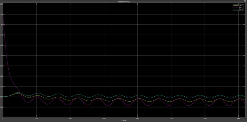
test 2). cell 5 temperature maximum than other cells.
As we can see that in cell 5 the temperature quickly falls 40 k and it fluctuate and end at 309 K.
state of charge wont be affected too much as the rise or fall in temperature isnt too much !
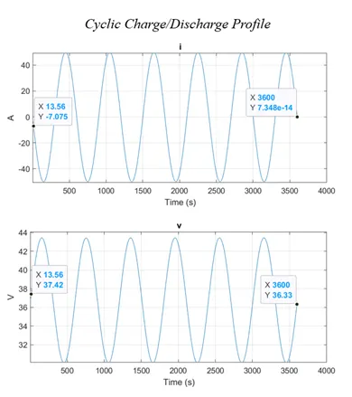
charge and discharge characteristic
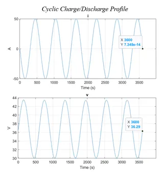
Again Charge and discharge profile are depending upon Current (I) and Voltage (V) vs Time. The cyclic charge and discharge were calculated at 50A peek amplitude.
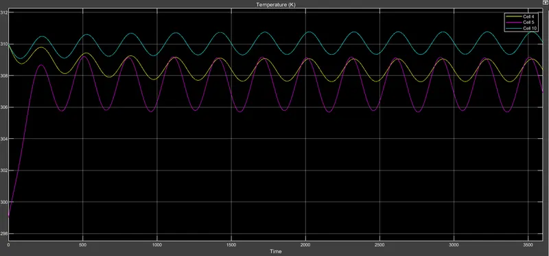
test 3). cell 5 temperature is minimum than other cells.
As we can see that in cell 5 the temperature rice till 312 and it goes fluctuating from 313 K to 307 K and end at 311 k.
state of charge will remain same ass the battery fluctuate every 301.200 seconds which totally depends upon the thermal behaviour of battery pack.
charge discharge cycle:
in conclusion:
we can say that the flow of heat increase with increase in charge and discharge cycle with respect to ampere and voltage rating it is providing at the output side
As I set fault in cell-5 and we can see that there is lots of fluctuation and temperature rise in cell-5 as compared with other cells connected in series
SOC for all different temperature are same, there is no changes in SOC
There is slightly changes in cyclic charge and discharge of cell which Is fixed at 50A as peek amplitude.