Week-7 Challenge: DC Motor Control
ans 1)explain matlab demo
in this matlab demo an igbt is used with paralled to diode (avoid reverse voltage) in h bridge configuration
so that it can be used to control over the rpm and the directon of rotation
starting with igbt which has higher voltage carrying and current carrying capacity
and a diode with parallel to igbt in order to avoid the reverse voltage protection
now as we can see in the figure below there are 4 igbt
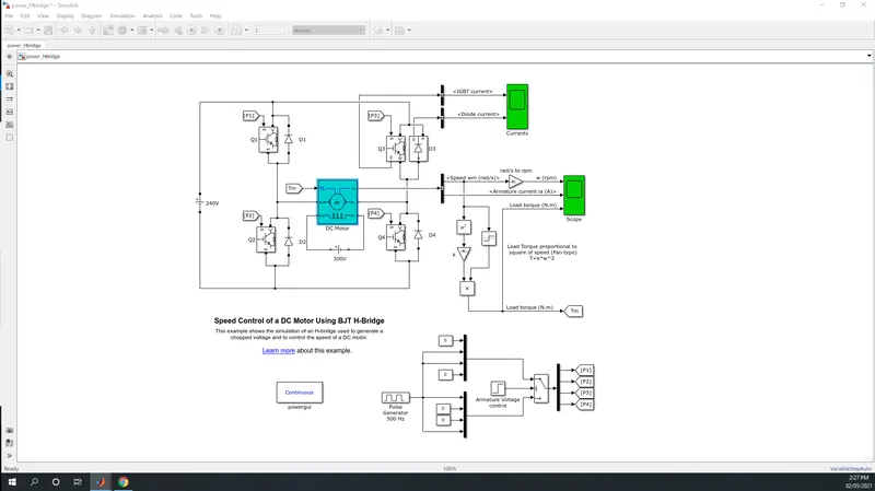
now as we can see that when igbt p1 and p4 will be provided pwm signal it will allow the current in forard bias to the motor and motor will run in clockwise direction the diode during this condition will act as a switch and wont allow the current to flow through p3 and p.
now if we want the dc motor to rotate in anti clockwise direction the pwm signal that was provided to p1 and p4 must be changed to p2 and p3 in this case the current will stop flowing through p1 and p4 and the polarity will be changed resulting in the reverse direction on motor
the current scope in the model is used to provide a visuals on the current that is flowing through igbt and diode
and pulse generator which is used to provide pwm signal to the igbt to control the voltage flow resulting in speed of motor.
and b). including that the current rise that we get on the initial stage of startiong of motor is due to the absence of back emf in dc motor and resistance of rotor winding which will result in current rise and high torque which produces a peak rise in current and this peak also takes place in a negative side because of the armature voltage in reverse direction when polarity is changed
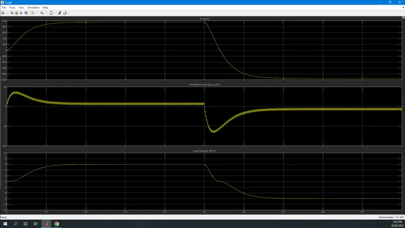
the simple way to overcome such peak current is to lower the current value by adding a external resistor to the armature winding and to achieve that diffrent methods are used such as
point starter and dc series motor starter method .
comparision of 4 quad chopper and H bridge
| 4 quad chopper | bjt h bridge |
| armature current varries while switching due to hig frequency | in this case the current peak are too high while switching from forward to reverse operation |
| it has high switching frequency | low switchiong frequency |
| to change the rotor direction the signals are interrupted | to change the direction of rotor polarity is changed |
| used for commercial and houshold operation | used in robot miniature circuits etc |
|
consist of 4 mode forward ,reverse,forward braking, reverse braking |
consist 2 mode forward and reverse |
ans 2). two quadrant chopper (type c and type d)
the equivalent construction inside the two quadrant chopper block in the simulink seems like as follows
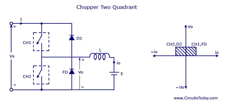
the main purpose or function of the 2 quadrant chopper circuit is to convert a fixed dc supply voltage into variable dc voltage either boost or buck
working when chopper ch2 is on or freeweeling diode fd conducts output voltage v0=vs and in case ch1 is on or diode 2 conduct output voltage v0=vs the load current i0can reverse its direction .current io flows in the arrow direction marked on the figure above when load current is negative if ch2 is on d2 conduct in other word ch1 and fd operate togetheras type a chopper in first quadrant likewise ch2 and d2 operate together as type b chopper in second quadrant
ans3). bldc motor working
a brushless dc motor is a permenent magnet synchronous motor which is driven by dc voltage in this motor the stator consist of winding Unlike conventional brushed type DC motor where the brushes make the mechanical contact with commutator on the rotor so as to form an electric path between a DC electric source and rotor armature windings BLDC motor employs electrical commutation with permanent magnet rotor and a stator with a sequence of coils. In this motor permanent magnet (or field poles) rotates and current carrying conductors are fixed The armature coils are switched electronically by transistors the position of rotor is obtained using a hall effect sensor The rotor position feedback from the sensor inorder to determine when to switch the armature current
construction:
bldc motor is of 2 type on the basis of constrution
inner rotor design ,outer rotor design
in inner rotor design the permenent magnet is located inside the stator winding or stator core
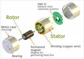
in outer rotor construction : the magnet are located on the rotor but this time the rotor is surrounding the stator core
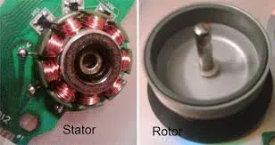
for example the motor used in drone, pc cooling fan
working
When the stator coils get a supply from source it becomes electromagnet and starts producing the uniform field in the air gap. Though the source of supply is DC switching makes to generate an AC voltage waveform with trapezoidal shape. Due to the force of interaction between electromagnet stator and permanent magnet rotor the rotor continues to rotate.With the switching of windings as High and Low signals, corresponding winding energized as North and South poles. The permanent magnet rotor with North and South poles align with stator poles which causes the motor to rotate.
application of bldc motor
Computer hard drives and DVD/CD players
Electric vehicles, hybrid vehicles, and electric bicycles
Industrial robots, CNC machine tools, and simple belt driven systems
Washing machines, compressors and dryers
Fans, pumps and blowers.