Project 1
Wiring Harness Project -1
Aim: To Route the wiring harness on the given enginee and prepare flattened view drawing in CATIA V5.
Introduction :
Definition of wiring Harness:
- The wiring harness is the combination of electrical cables,assembly of wires that connects all electrical and electronic components in the automotive vechicles , like sensors, electronic controls units , batteries and actuators .the wiring harness handles the energy and information flow within the electrical and electronic systems to fulfill primary car functions, such as steering and bracking , ventilation .
- Generally , wiring harness are made of thermoplastic or thermoset that can helps to protect the cable .
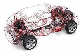
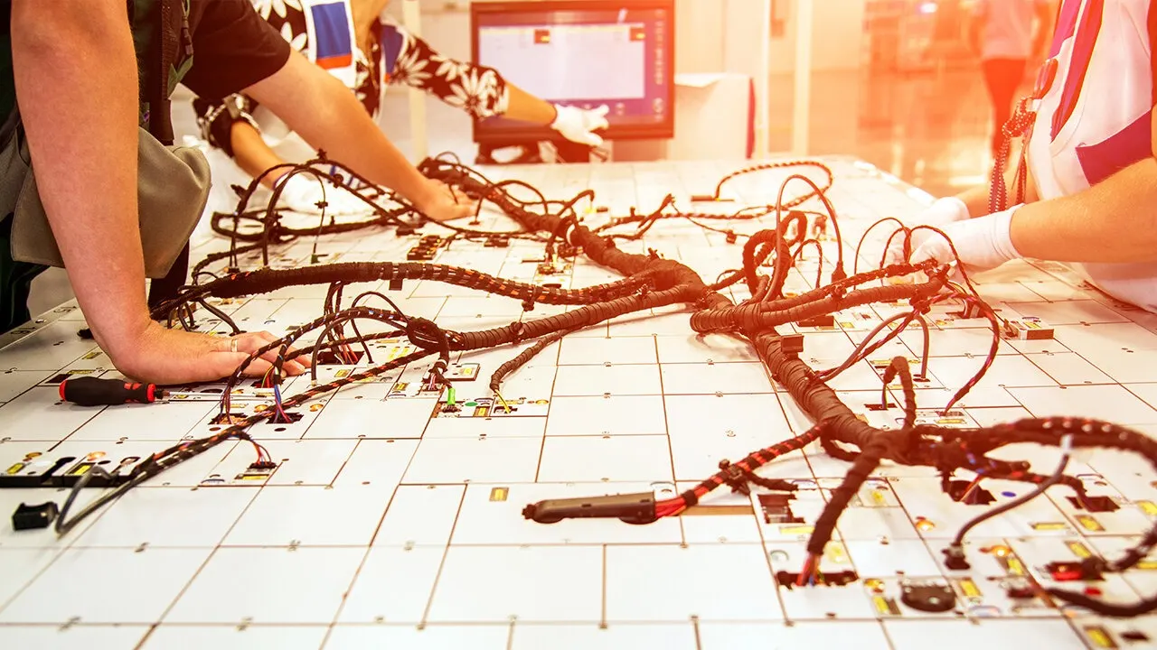
- Automobiles and other road vehicles such as trucks and busnes are one of the most demanding appliacation for mechanical and electrical design . the electrical systems in these application must operate properly over a wide range of environemental conditions, facing extreme temperature , humidity ,sunslights , dirt,vibration and more.
- The electrical systems must also meet user expextation of reliability and mandatory safety-critical design practices .
Objectives :
- Define the mechanical components electrically and prepare the catalogue .
- Placeing all the connectors in required poisitons .
- Proper routing of the Bundle without and interference and also provide support parts like clips and clamps .
- Create protection covering as required .
- creating the flattening file using flatteing workbench.
- creating the 2D drawing using drafting workbench .
Procedure :
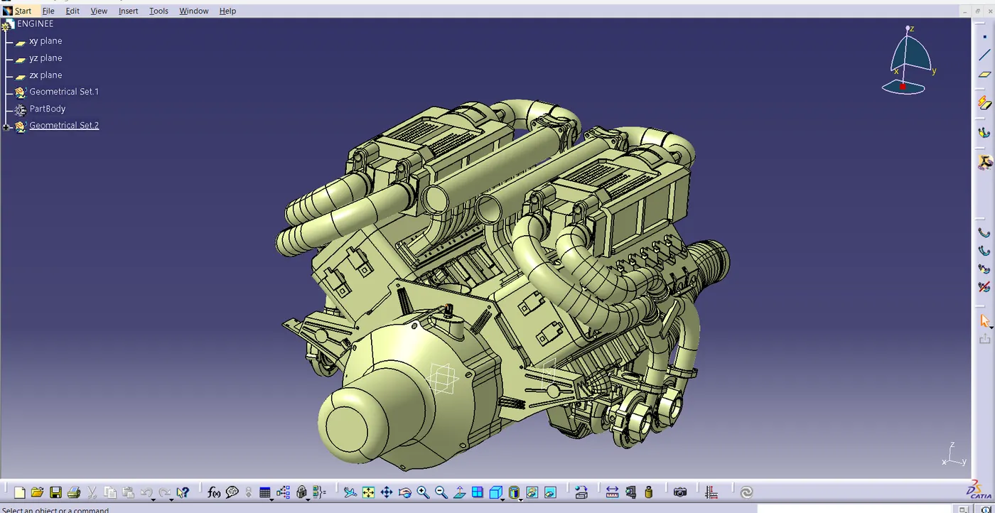
- Download the Enginee cad file and connectors form the given link .
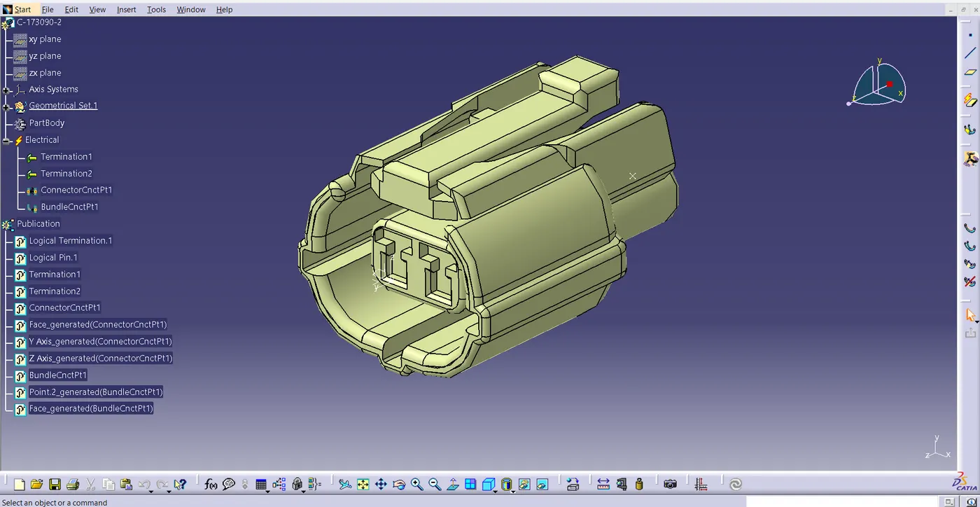
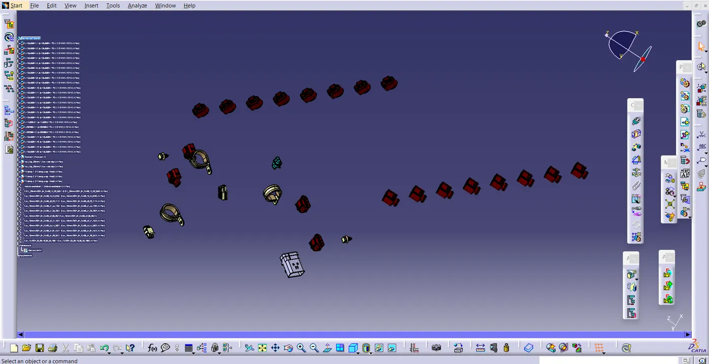
- After downloading connectors and enginee files, define the connectors electrically as showen in the figure .
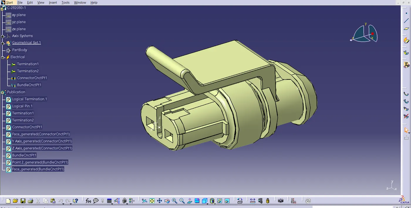
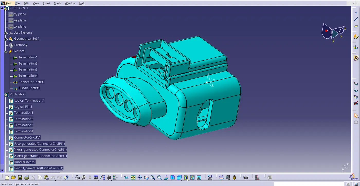
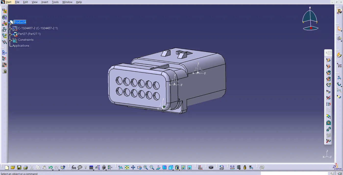
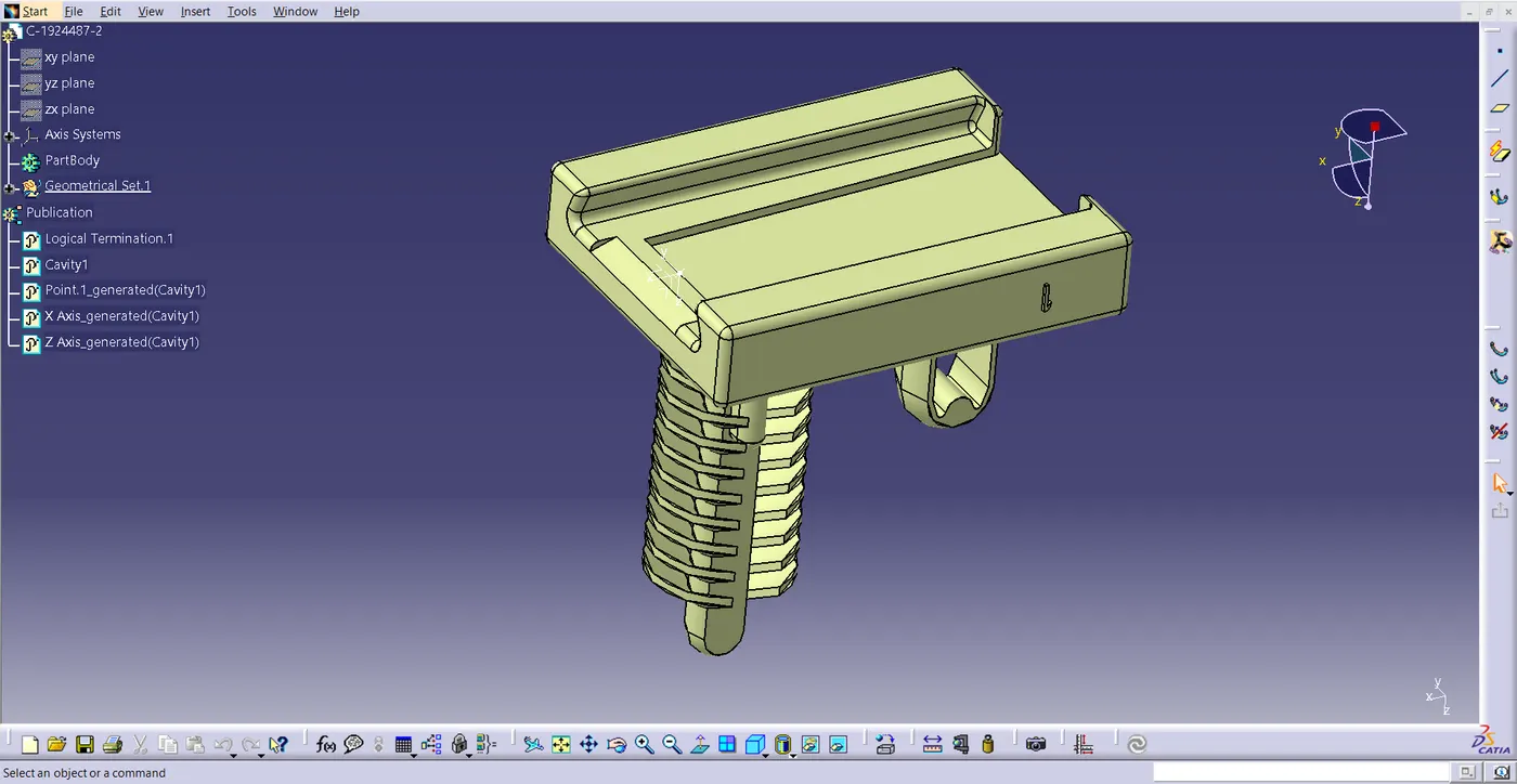
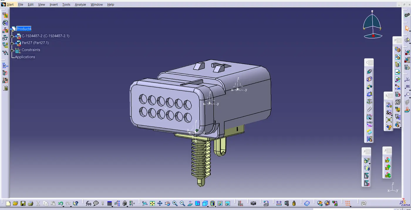
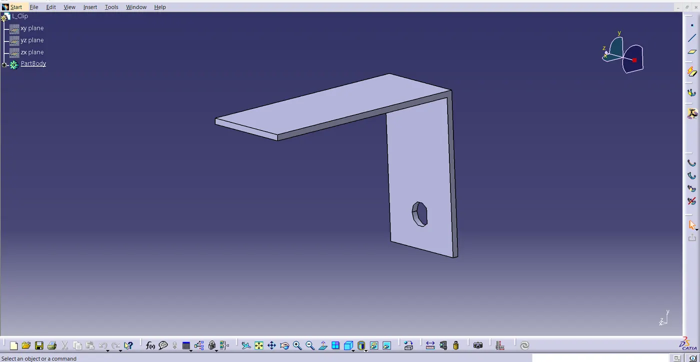
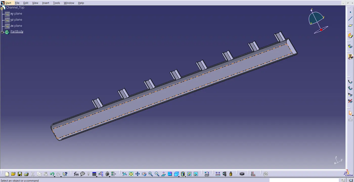
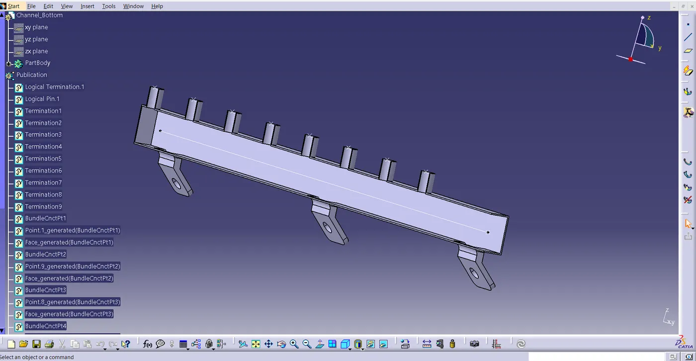
\
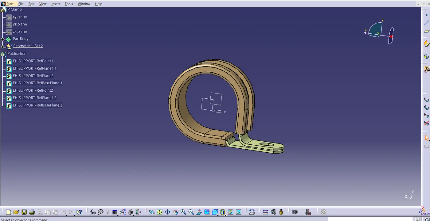
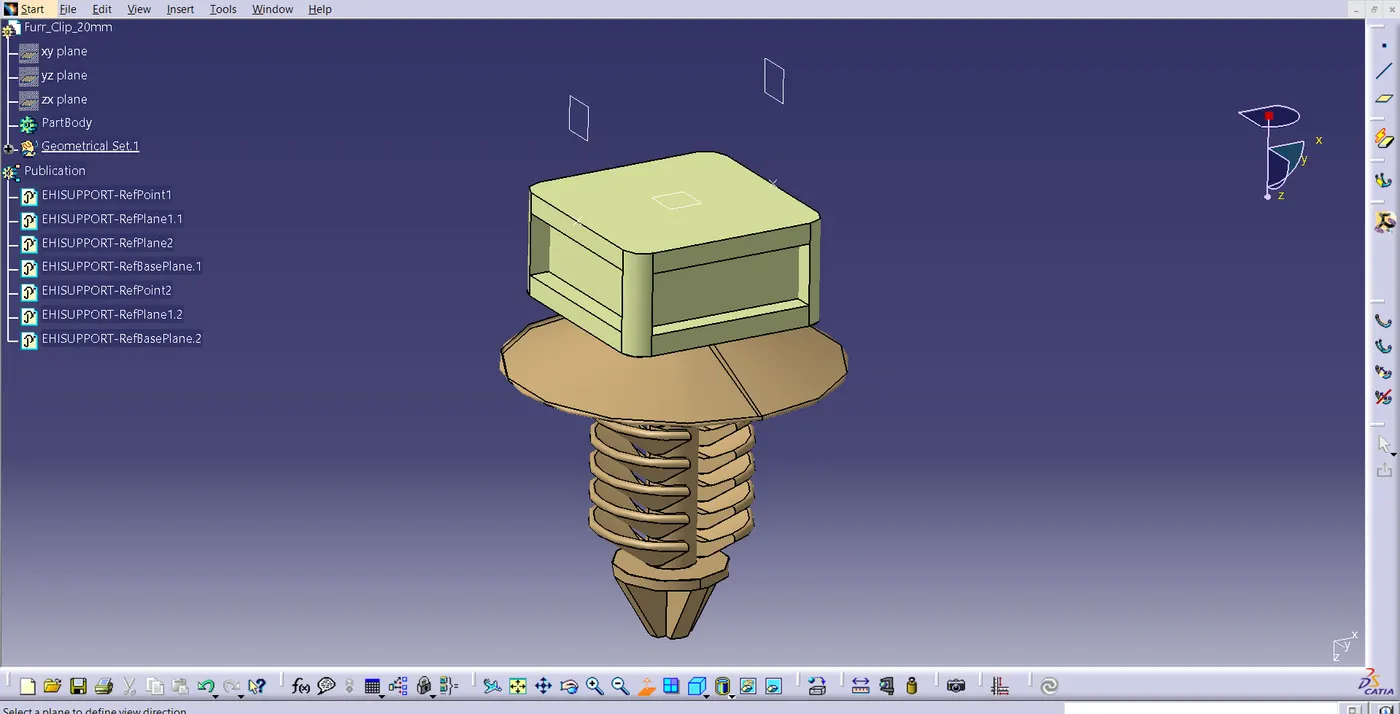
- now open Assemply design and Copy the Enginee Design and past it on Assembly design then add new product and rename it (Gemoentrical bundle1 (Connectors) .and save this product in same context assembly .
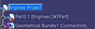
- Now Insert the connector in gemoentrical bundle (connector ). follow the below point to define the connector electrically.
- Create a midpoint on the Bunddle connection point .
- Then create an another midpoint on contact face which will be normal to wire bunddle insertion.
- Create a Axis system respect to the point which we have created .
- After completing the Axis system. Then switch to "Electrical part Design" .
- Select the Define connector tool and select the connector and given termination .
- then select Define Bundle connection point definition Tool and select the Rare face of the connector .
- Then Select Connector Connection point then select the point first and select the Front face as contact and coincidence Y-direction,orientation as X-axis .
- now take the P clamp and furr tree and define it electrically .
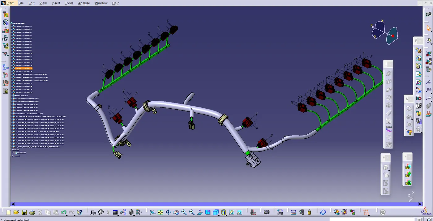
- After defining all the connectors electrically . then position the connector, clamps ...as show in the fig. by using compass and manipulation ,snap,smart move tools .
- Now do the routing for the connector , go to electrical harness Assembly, convert all the connector electrically by using the tool of geomentrical bundle .
- now route the connectors starting form 12 Pole connector .
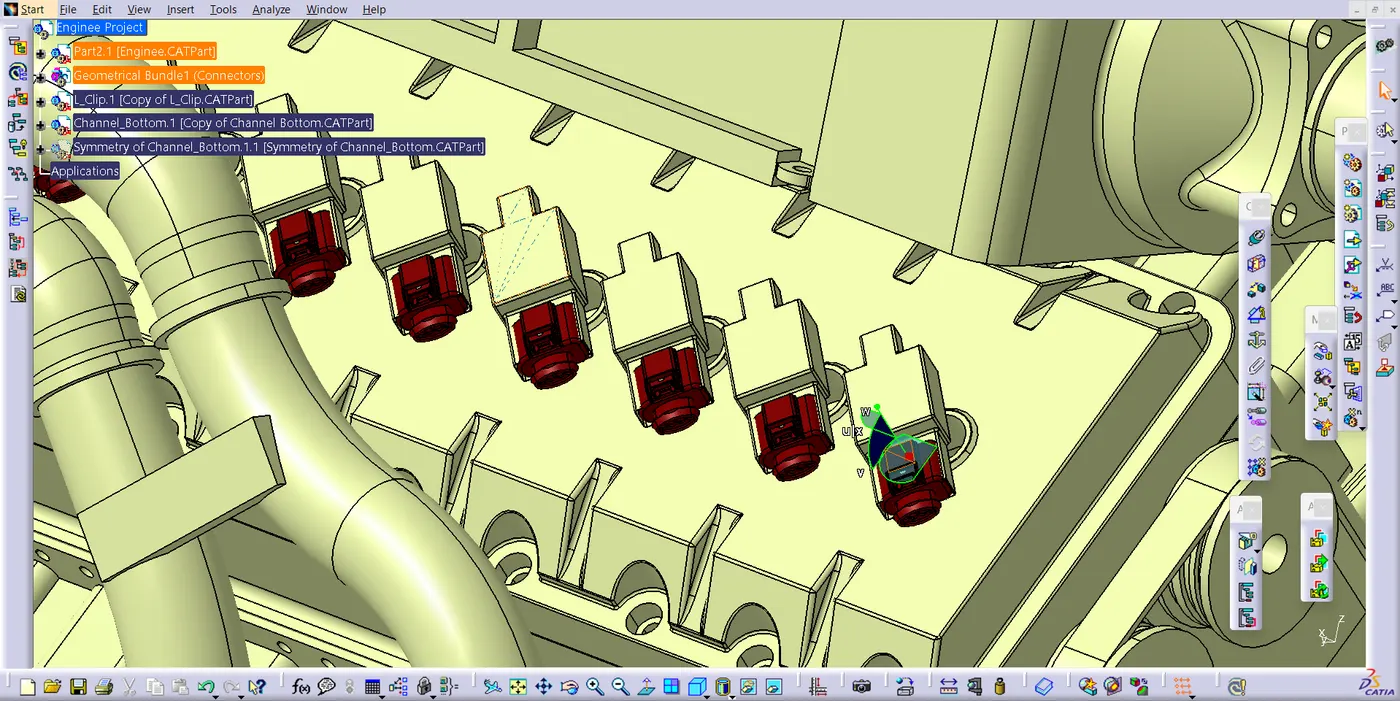
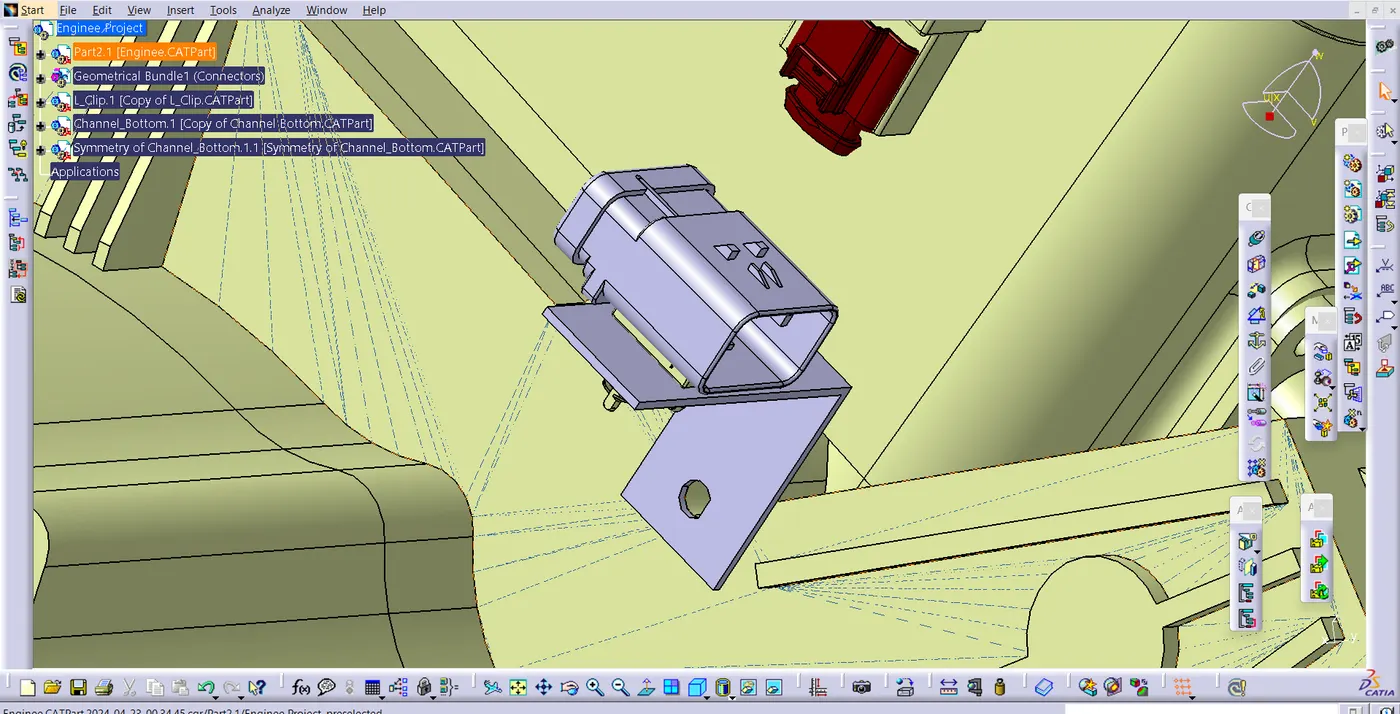
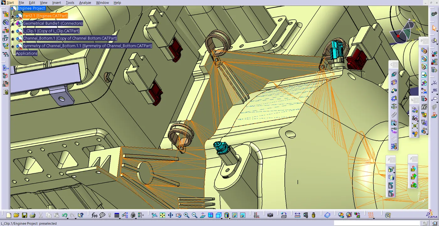
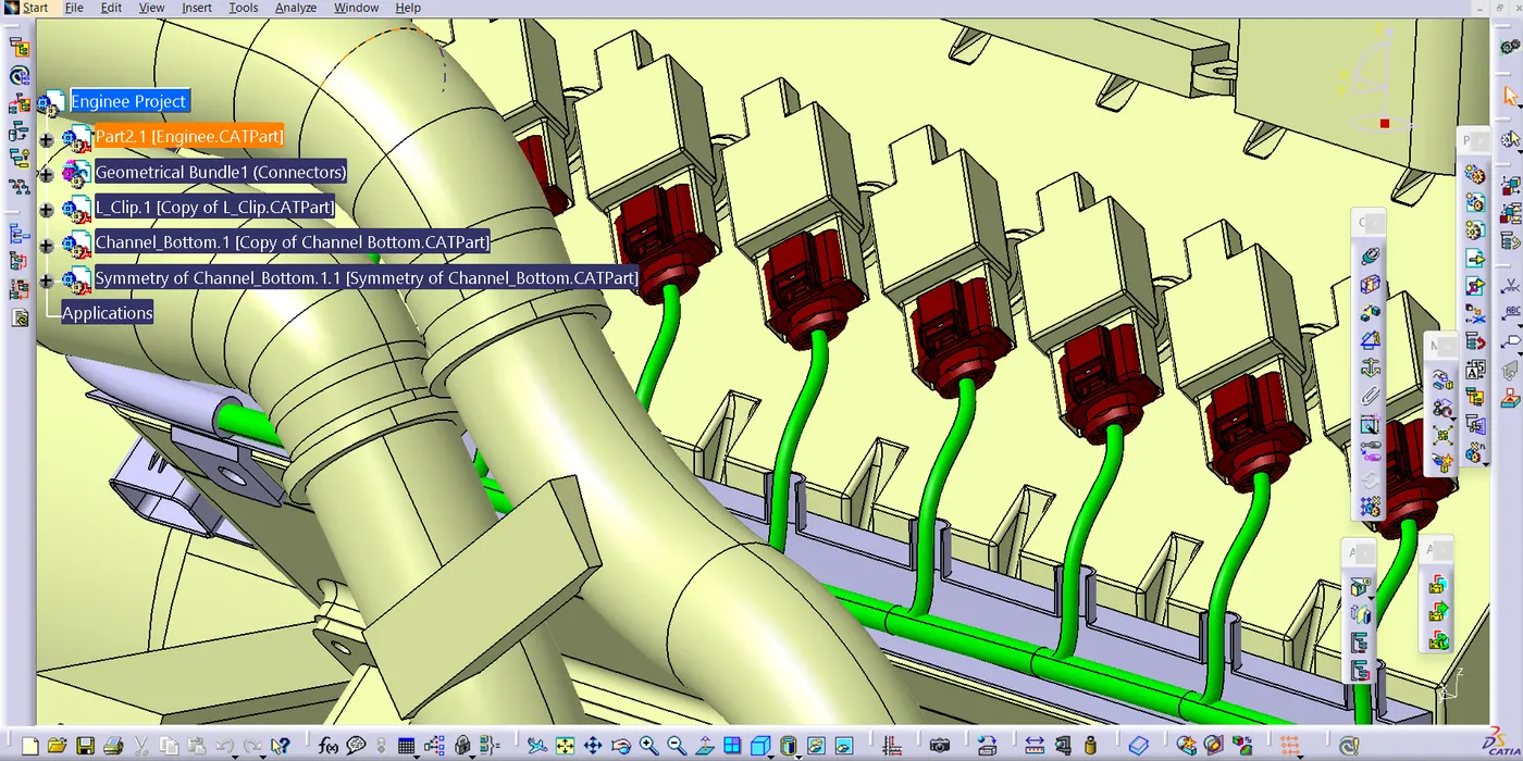
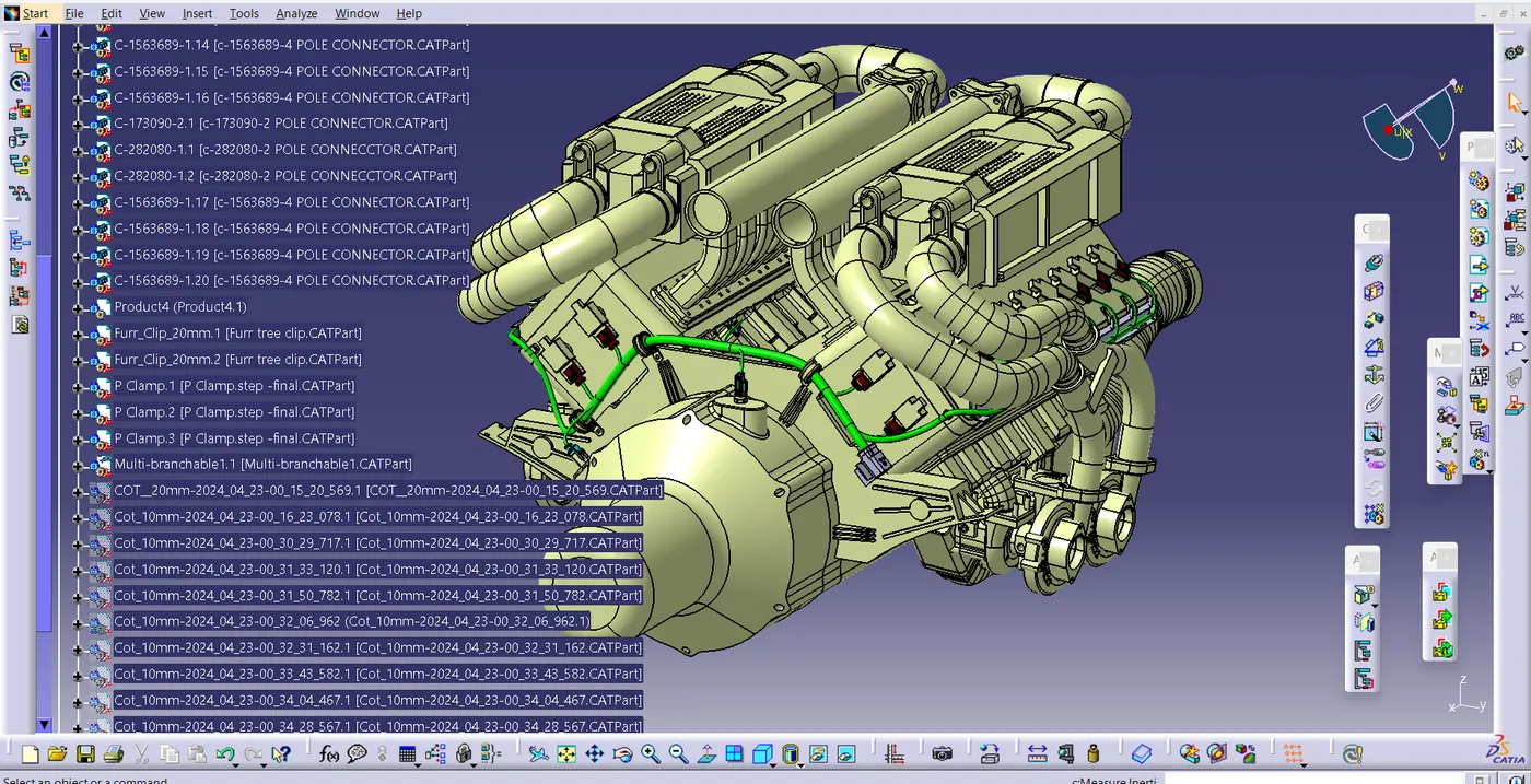
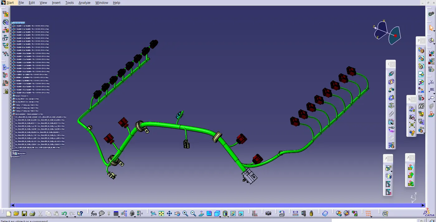
- After Routing add protection cover to the wire .
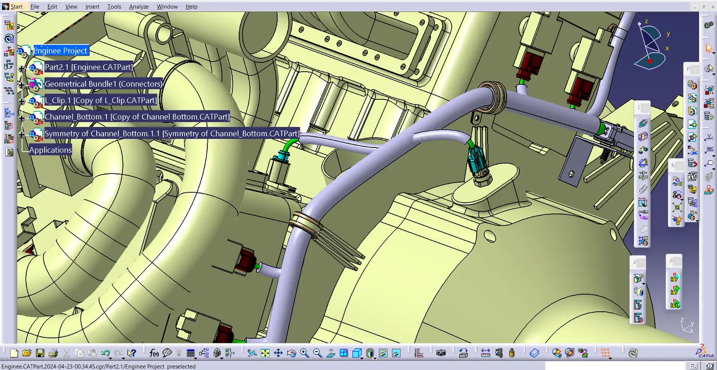
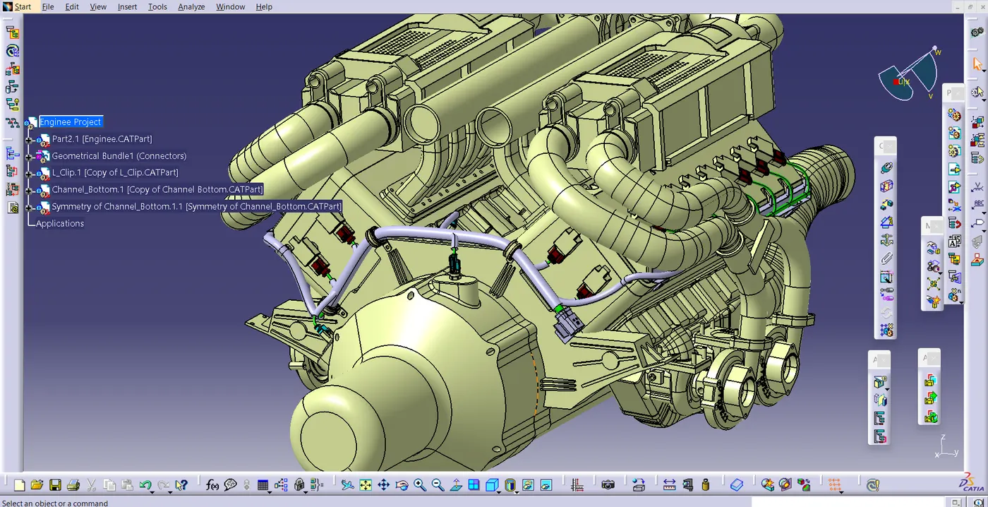
Wiring Harness Flattening :-
- Wiring harness bundle packaging process was done.now we need to convert the geomentrical bundle into a flattened wiring harness in the electrical harness flattering workbench.
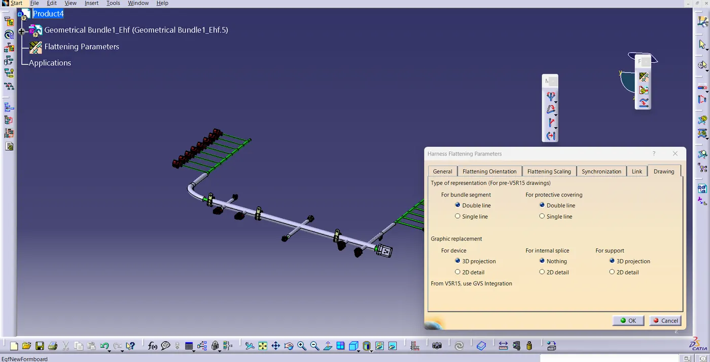
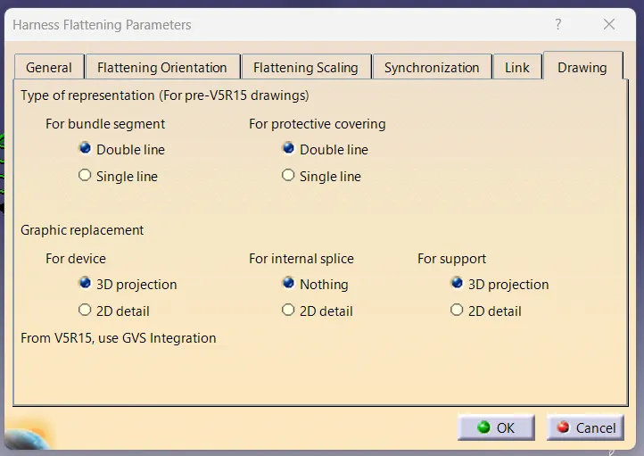
- Open Flattering workbench , select harness flattering paramateres change the setting according to the project . then click OK.
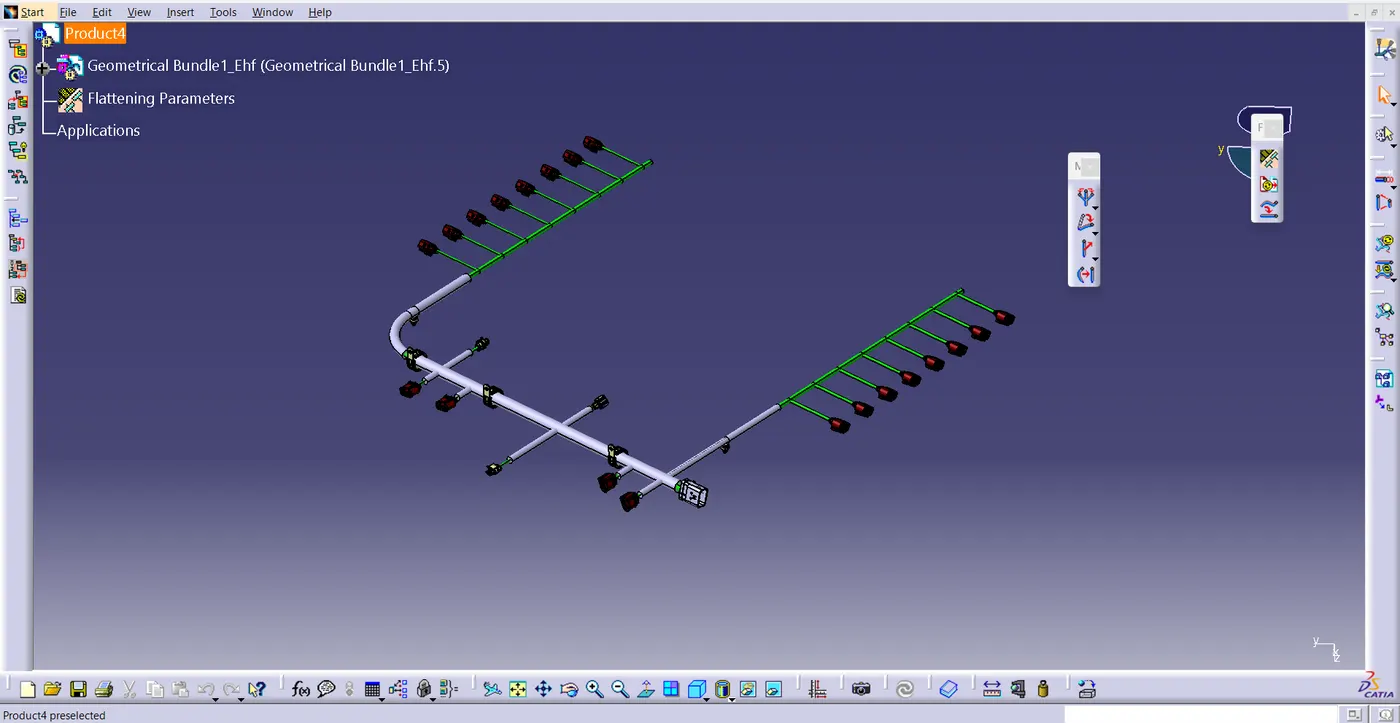
- now press the extract tool and select the geomentric bundle from the wiring harness context product file .
- Then select flatten tool and select the Bundle and select all click ok .
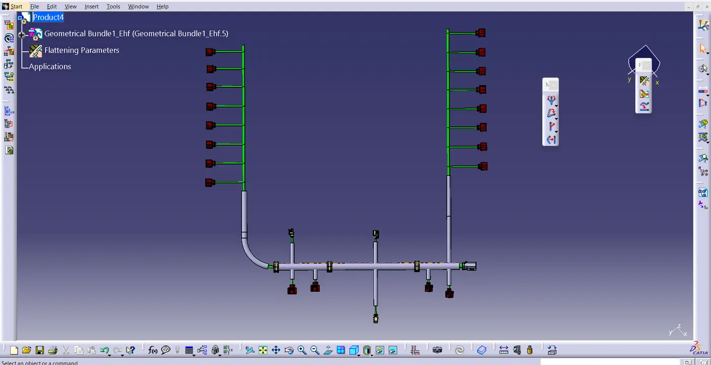
- Now Rotate the Bundle with a proper radius as shown in the fig.
Flattened view drawing
- Create a new drawing file in the drafting workbench and make sure that Flattern parameter settings bundle segment and protective covering have different as showen in the figure .
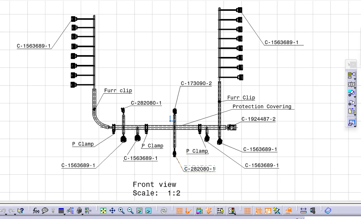
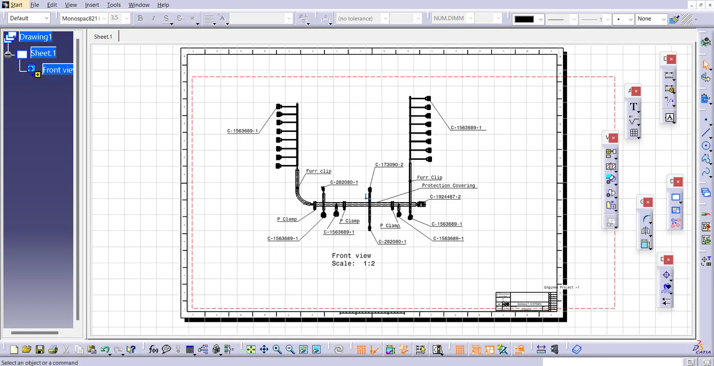
- Now Insert the flattened harness product in to the drawing sheet using view front tool .
- By add text mention the name of the connector.
- Modify the drawing sheet according to the requirement .
Conclusion:
- Hence the Routing of enginee and preparing flattened view drawing was done by using CATIA V5.
NOTE:
- This file was not getting upload Due to Big file size. so, I have attached the Drive link .
- if the link is not working please contact
- https://drive.google.com/file/d/1buBfX_tVxIUkcW-jzfbZDJTkBwjCv-M_/view?usp=sharing