Week 10 - Challenge 1- Attachment Feature Creation (Ribs & Screw Boss)
Creating Door Handle Component .
Aim:
1) To create a tooling Axis from the given Class A Surface .
2) To Attach B surface in class A surface.
3)To create RIB and SCREW BOSS .
4)To Perform Draft Analysis .
Procedure:
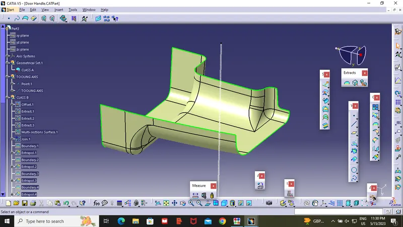
- Creating a Door handle component from the given class A Surface and creating the tooling Axis .
- Crating Tooling Axis
The tooling Axis is Basically the direction that the mold pulls a part . we have a cavity and core side .the core pulls apart from the Cavity and that Dye line (tooling Axis).
- Draft Analysis:
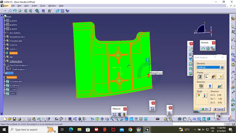
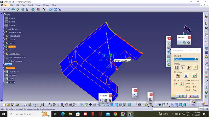
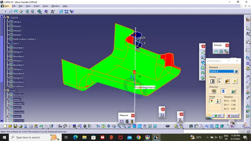
Generally the draft analysis helps to Identify the part you draft will be easily removed are not .So now Check the draft analysis by clicking the draft analysis tool.
a)First step is to click on the customized view paramater then under mesh then Select the material then Ok.
b)use the compass to define the new current draft direction.
c)Place the compass on the Tooling Axis Line .
- Creating Class B Surface:
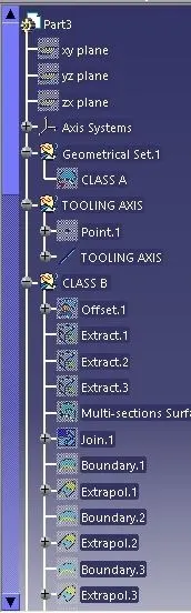
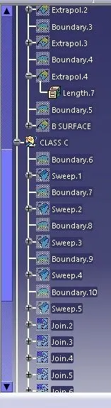
1)Offect the Class A Surface to 2.5mm by using the Offect command then OK . Some error like in sub element click ok. by using the Multi section Surface Close the open surface in the B Class.Then Join the Surface. Exprapolate the Bourders of the Class B Surface up to 5mm . Class B Surface Was Completed .
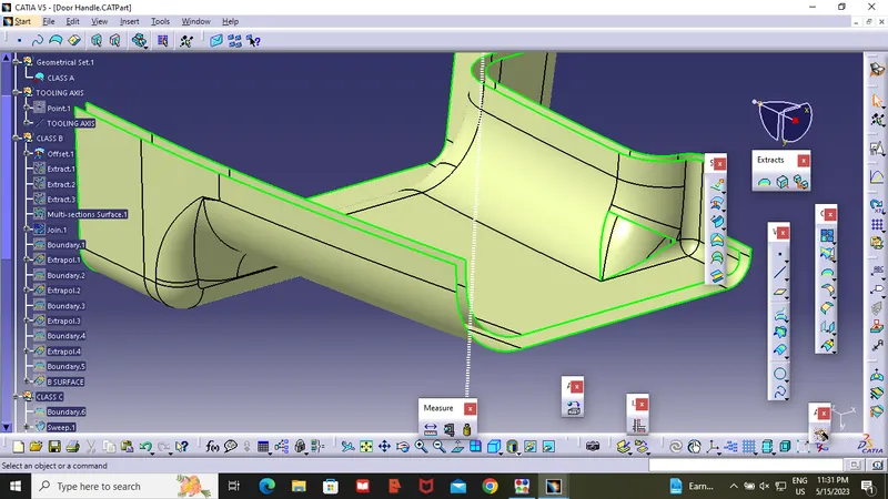
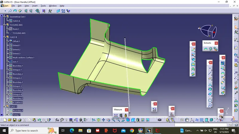
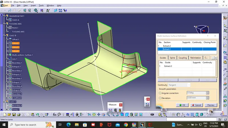
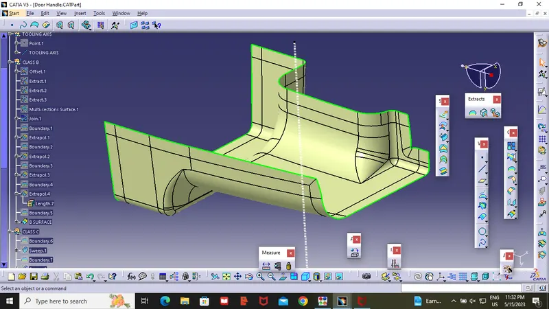
- Class C Surafce .
- Take the class A surface and Extract the Boundray
- Using the Sweep Command > Line > with resepect surafce (select the boundary and surface .angle will be 90 degrees.)
- After Creating the class C surface Join Class A And Class C surface .
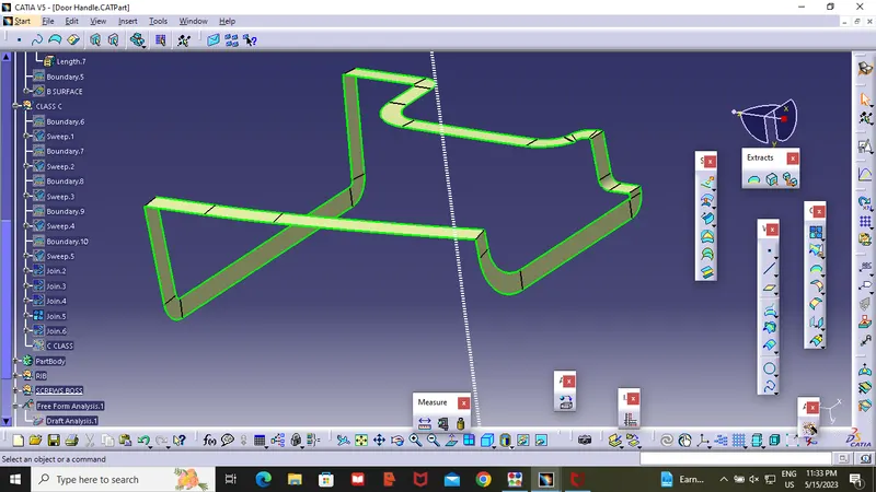
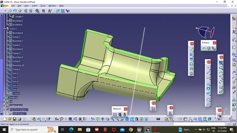
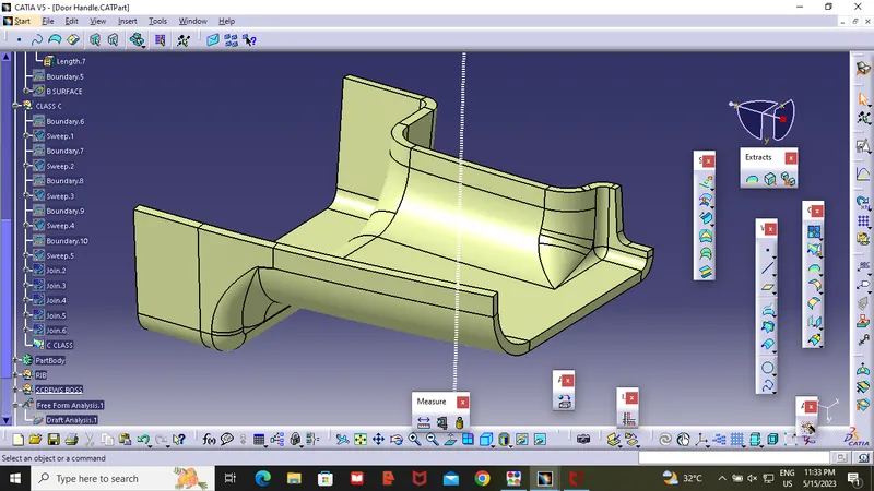
- Now Unhide Class B surface . Trim it the Extra surface in class B and Class C .
- Then you will get the Final Component .
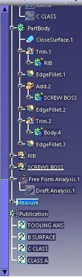
- Part Body .
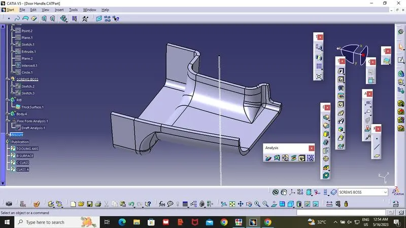
- After Completing the final Component Change it to material by using Closed surface tool.
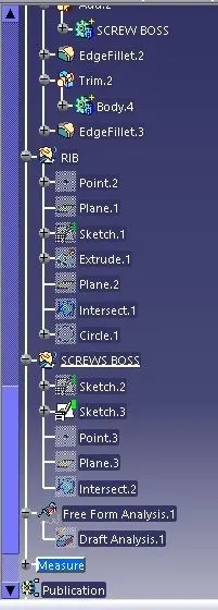
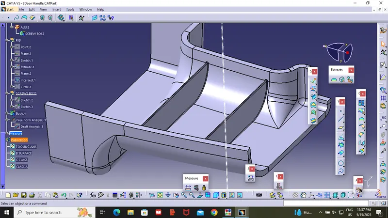
RIB Creation .
- RIB provide a means to economical stiffness and strength in molded paets without increasing
overall wall thick ness.They Commanly Use to add additional Support to the Component .
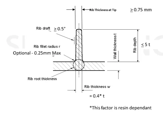
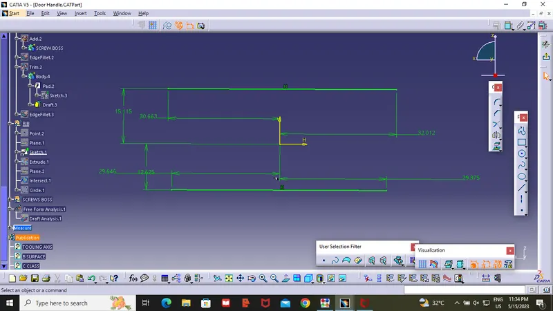
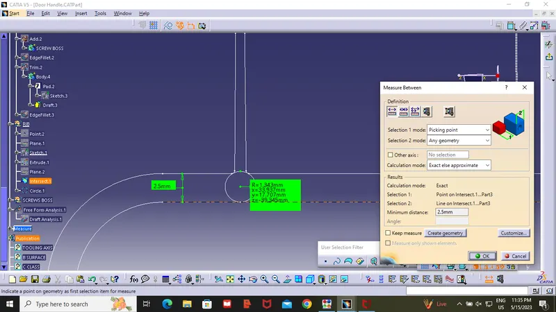
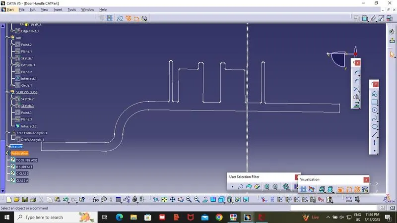
- By creating a plane on the center (YZ Reference plane) and by using the intersection you can check Rib is correct or wrong
- Screw Boss :screw Boss feature commonly found in injection molding design . they are used to aid in the assembly of molding parts by providing a channel for a screw .
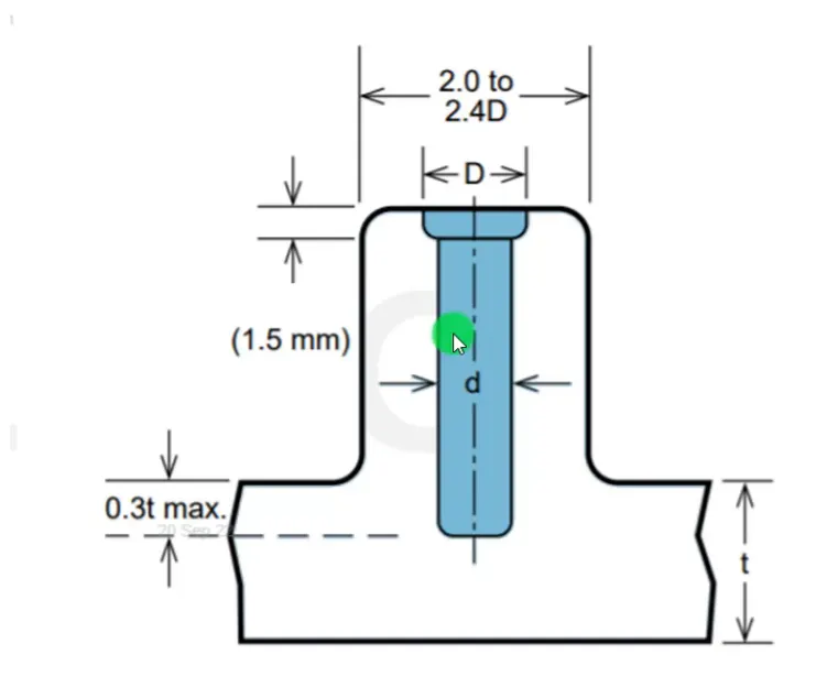
- Creating the Screw Boss
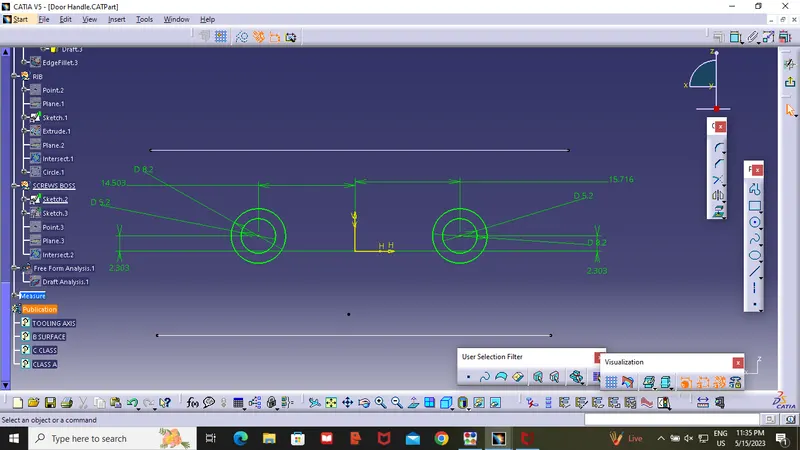
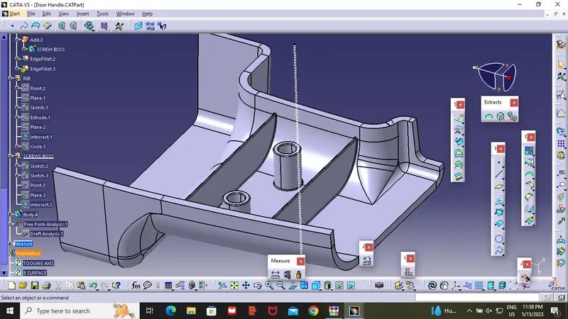
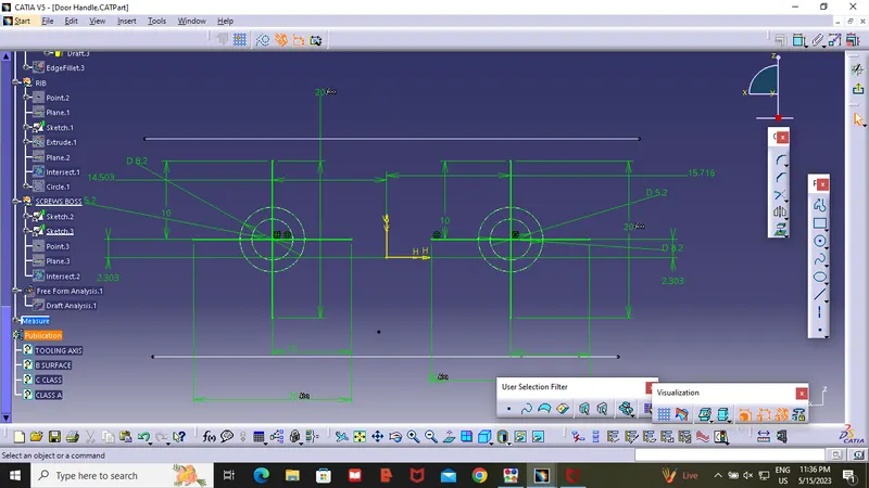
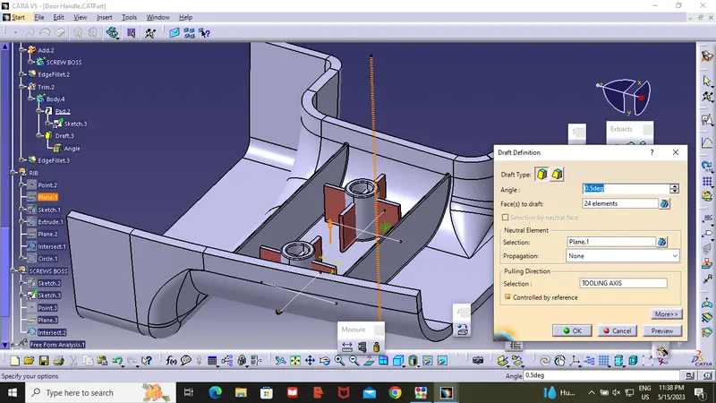
- By creating a reference plane on YZ direction on screw boss and by using the intersection you can check screw boss is correct or wrong .
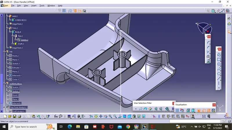
- Draft analysis:
- After Completing the Component .Use the Draft Analysis command .
- Place the compass on the tooling Axis and check wether the material is producible are not .
- Following Images Show that our solid Body is correct Because it is passing through the Draft Analysis .