Week 10 - Challenge 3 - Door Trim Lower with Engineering Features
Door Trim
Aim: To create the door trim component through the given Class A Surface .
Objective :
- Creating a Proper tooling axis Considering the Required draft angle .
- creating of class B and class C Surface
- Adding the Heatstake and Locators to the door
- Performing the Draft Analysis.
Procedure :
Givan Class A Surface
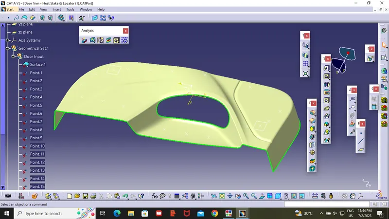
Tooling Axis :
Before going to the tooling Axis Check the component whether the surface is having any open surface in the middle , by using the boundary option you can check the component .
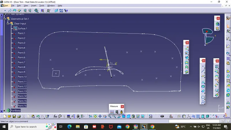
To create a tooling Axis ,I Created a point on the surface then Added a plane on the point , and sketched the surafce on XY direction, by using 3D geometry (intersect 3D elements ) .I have created a line on the middle of the surface then by using bisecting line ,I have created the tooling axis as showen in the figure .after completing the tooling axis i have checked the Tooling Axis whether the created tooling axis is in the correct position or not by using draft Method .Hence the tooling Axis is covering all the compenent.
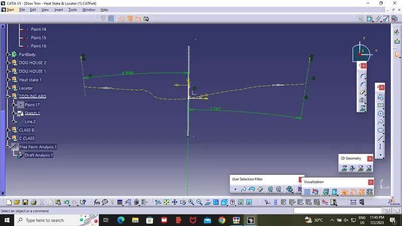
Class B :
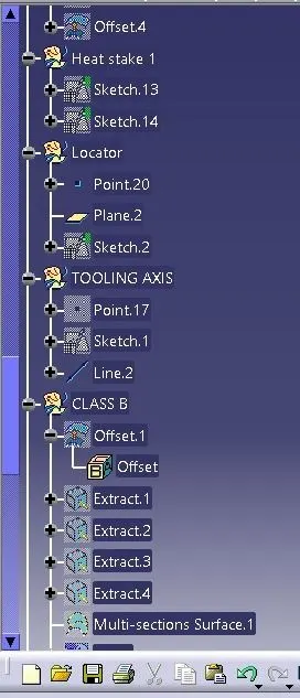
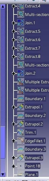
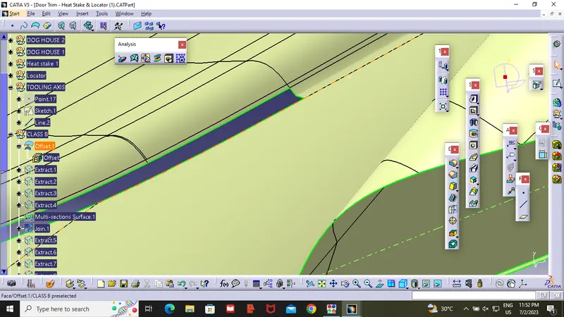
After completing the Tooling Axis the next step is to create Class B , first we need to offset the class A surface at 2.5mm to the inner diection of the component . After Offset we get some open paches . to close the open paches I used Multi-section surface ,After closing all the open Patches , we need to give the fillet at required place's .
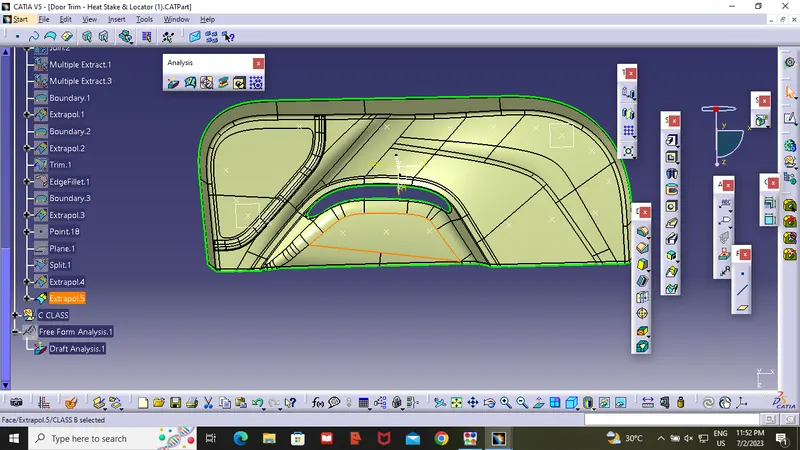
Then Extract the boundary of the class B surface up to 5-10mm .
Class C Surface :
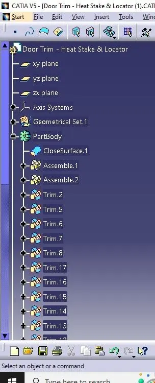
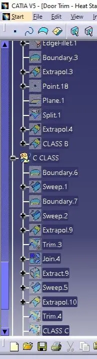
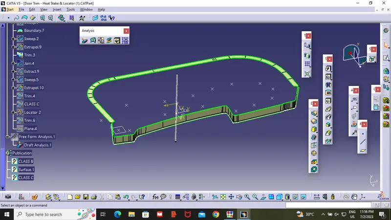
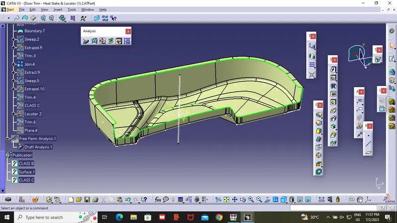
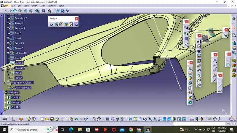
Insert a geometrical set and name it as Class C Surface ,Unhide the class A Surface ,create Boundary lines by using extract or boundary command , after getting the lines , by using sweep command we create a extand of class A at 3 degree .As showen in the figure . after completing the class c surafce unhide the class B surafce .By using the trim option trim the extra surface from class A and Class C. then we will get a Closed Surface . After getting the closed surface . check the component whether it is have any open surface in the middle . our's component is closed component . so we can convert the Surface to closed material by going in the part design then to closed surface option .
Creating the Locators :
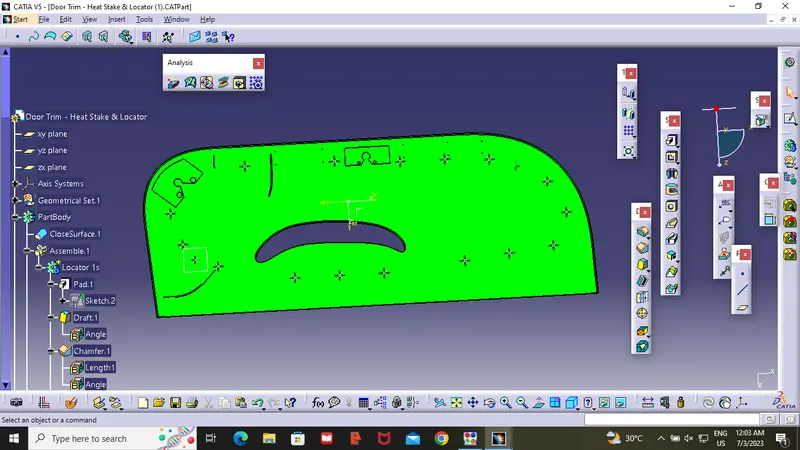
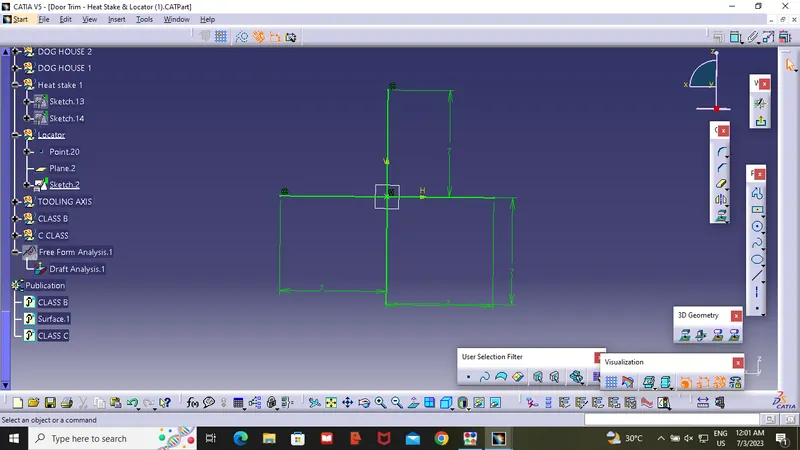
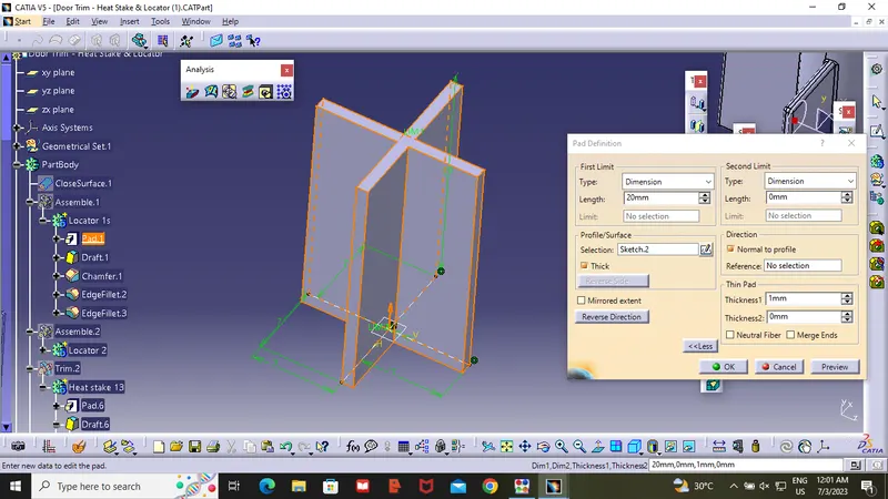
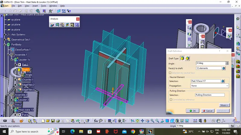
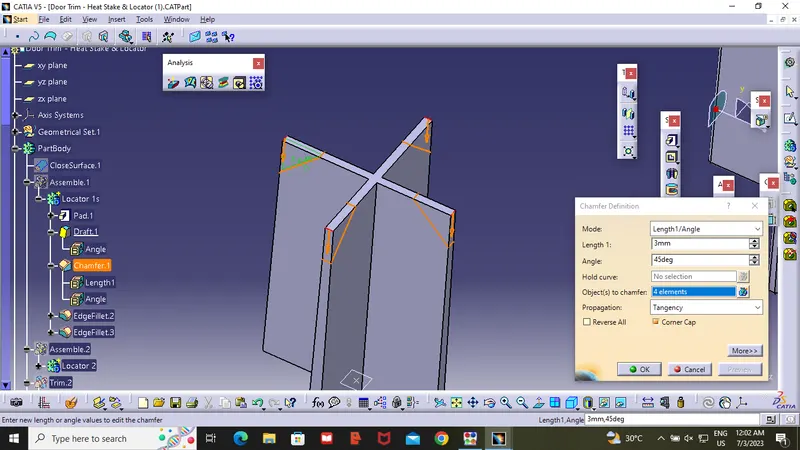
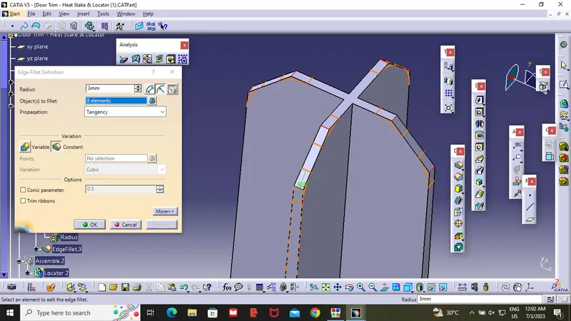
To Create a Locator I have taken a point and added a plane on that point ,then skech on the Plane ,After creating the sketch , Pad it up to 20mm in the hight and 14mm width ,then draft it with 0.5deg in the direction of the tooling Axis .then i have given 5mm Chamfer with 45mmdeg of inclination and after then give fillet of 0.25mm radius .
Creating the Heat Stakes :
To create the heat stakes , create a sketch on the surface , pad it to 15mm hight after that i have given a draft angle of 0.5deg on both side out and in side's .and fillet of 0.25mm. After creating the heat stake, i have created rib's for the support .with length of 20mm and pad it to 10mm hight after that i have given draft for all side ribes it 0.5deg with respect to the tooling axis . the fillet the edges at 0.25mm.
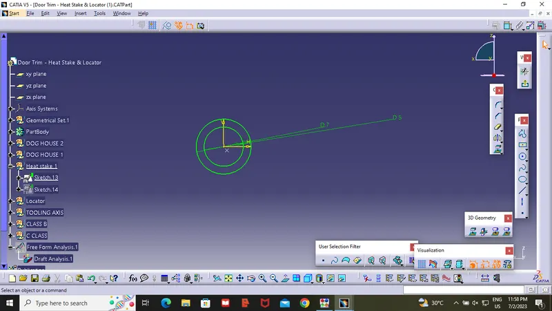
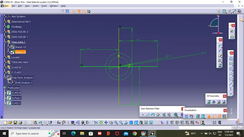
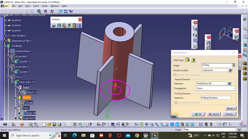
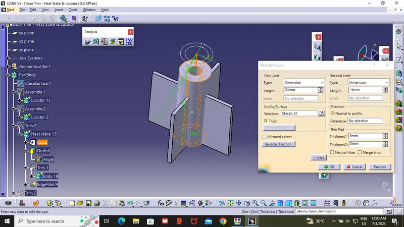
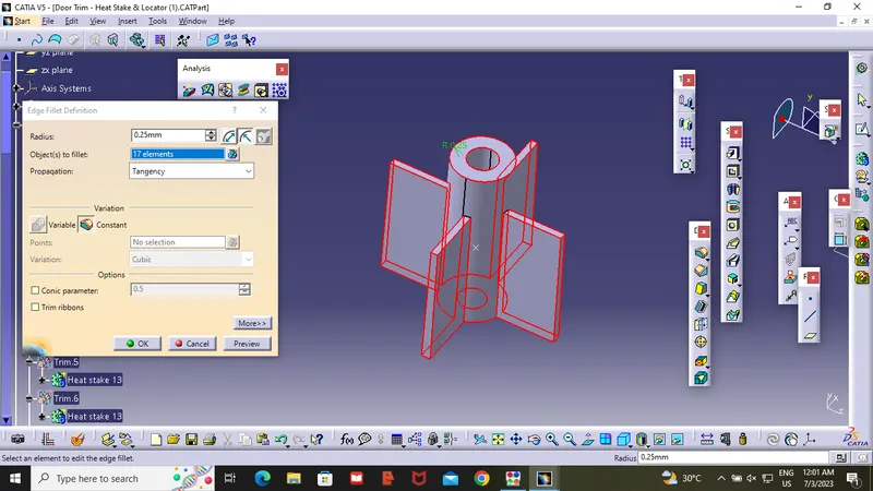
After creating one Heat stake Copy the body sketch of heat stake and go to door trim right click and select past special then select AS Result with the line .then click transalate option point to point .select the first heat stake point the empty point .
Creating Rib:
Ribs is a Feature in plastic injection Molded parts.They are in Thin extensions that run perpendicular from the awall or plane .
This ribes are commonly used to provide Addition support the Part .
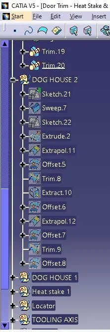
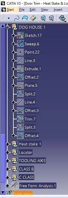
Procedure to Make Dog House :
- Create a point on the surface and crate plane on that point .As showen in the fig. Draw the Sketch On that Plane .
- After creating the Sketch Use the Sweep commend to extraxt the Sketch at 1.5 Degree .After completing the side walls Create a Line on the point in Y-direction . Extract the line and offect the Extract to 20mm top .after that using the trim option make it as a shell .
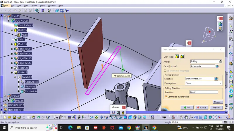
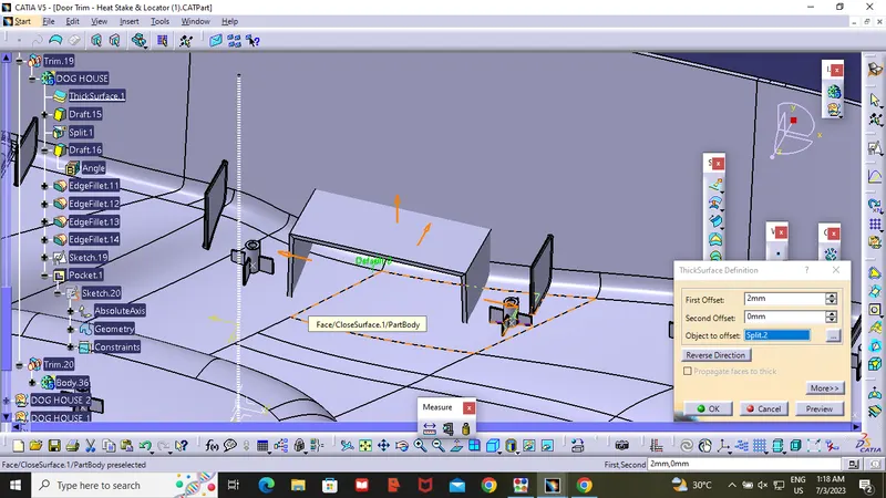
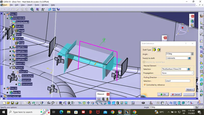
- After getting shell insert a body and use Thicksurface command to shell in outer side with 2mm. then use draft command .draft the innter part at 0.5mm .Then use fillet commend to make the innter surface smooth .
- After compleating this process Unhide the Y-direction line extract and offset.and unhide shell and Offset it to 1mm as show in the figure . Trim Extract Surface with respect to Shell then you will get Step Shaped surface .Then go to part design and choose Trim option and trim the step surface .
- Then Draft the trimed part with 0.5mm.then fillet the outer sharp edge to 3mm.then extract the Backside of dog house and offset it .
- Repeat the same process for Another Dog House .
- Note : in this Challange we created only two doghouses because on the another side there is a Locator and Hearstake
Draft :
Draft is Providing angle or Taper on the product feature such as walls, ribs, posts and bosses that parallel to the direction of the releated from the mold eases part ejection .
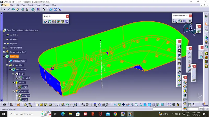
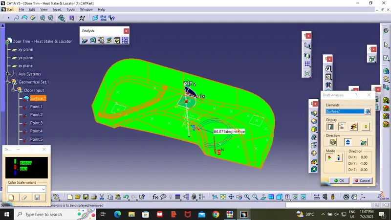
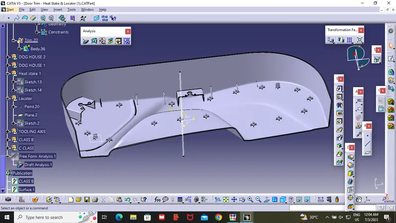
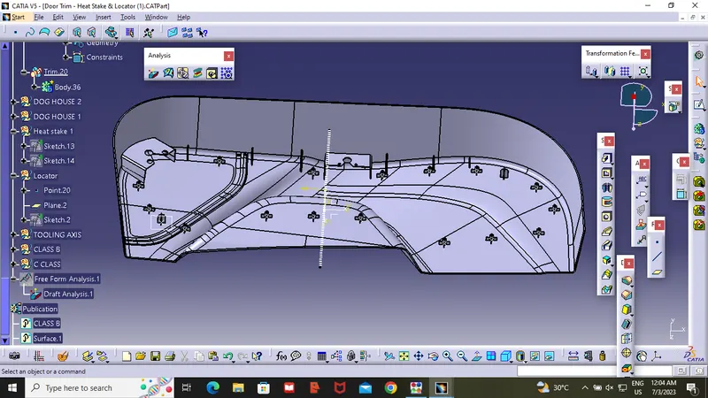
After Completing the Component .Use the Draft Analysis command .
Place the compass on the tooling Axis and check wether the material is producible are not .
Following Images Show that our solid Body is correct Because it is passing through the Draft Analysis