Week 9 - Challenge 3 - Bumper
Bumper Challenge
Procedure :
1) Class A Surface is Given as Input .Then the Design was started by checking the quality of class A surface by using the boundary Command . the boundary line was continous and good to continue .
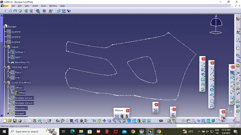
2)Then we need to check where the tooling Axis is to be created .we need to check X,Y,Z Axis . In X - Axis direction we can see all the patches in class A Surface . so X-Axis was selected to create the tooling Axis.
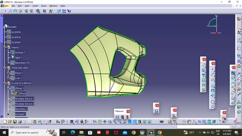
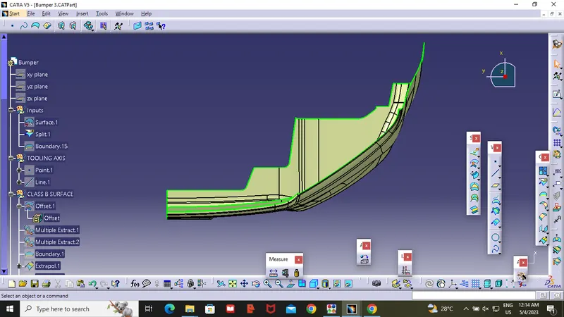
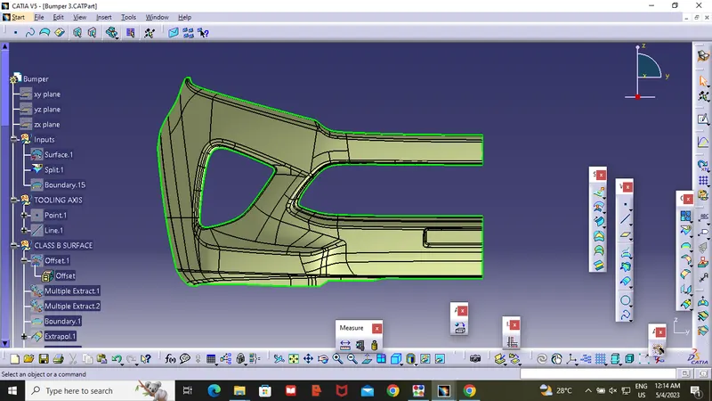
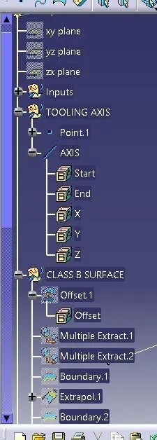
3)Then use the point and line(point to direction) command to create the Tooling Axis.
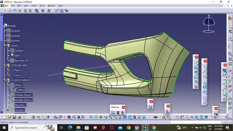
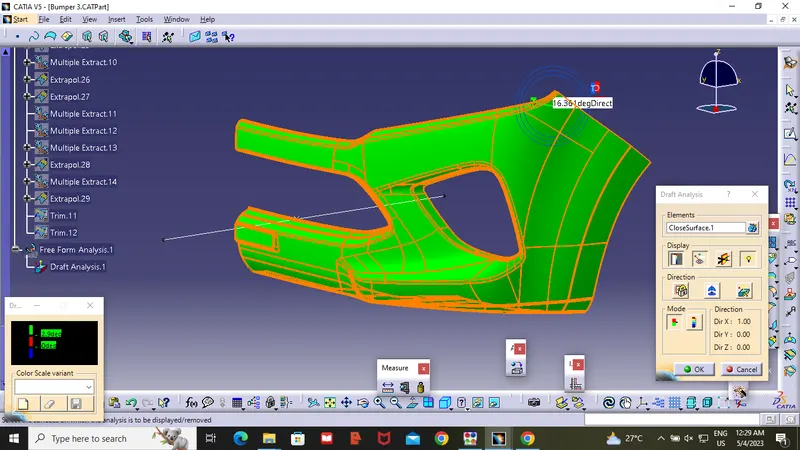
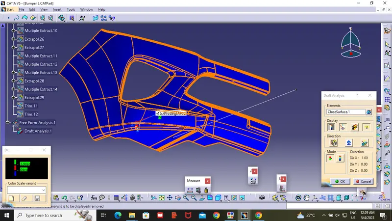
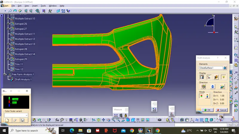
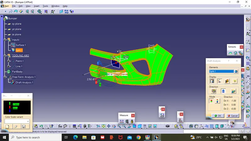
4)After that we need to check this Tooling Axis is correct or wrong in postion. by using draft Analysis we can check. If Surface ] are green color our tooling Axis is correct.
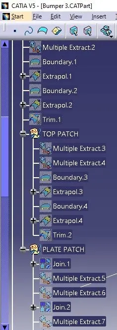
5)Class B Surface : Create a Geomentrial set and name it as Class B surface .then offect class A Surface at 3mm(thick ness of the part) .after offecting the surface some open surface formed in class B surface .by using multi extract and complementary mode, and by using Boundary line we extracted the surface at one side .by using the Extrapolated option we extrated the surface and trimed the surface .
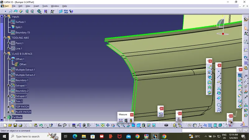
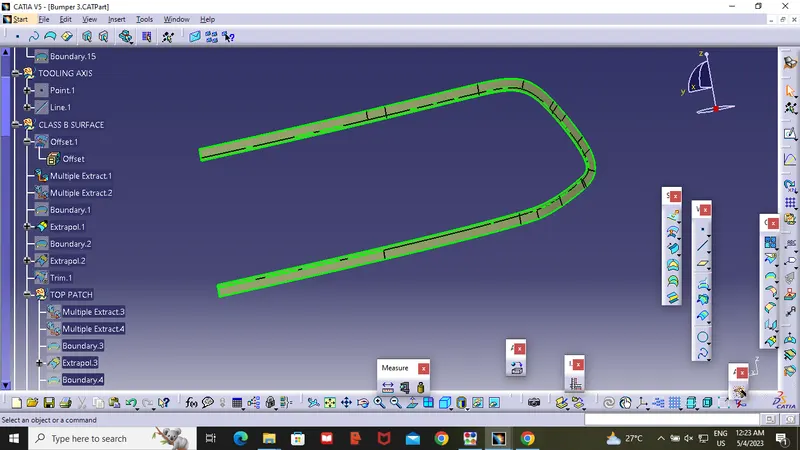
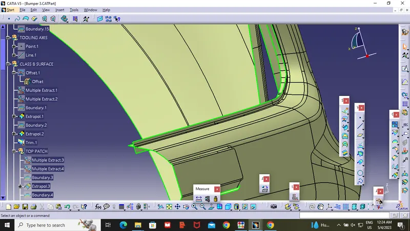
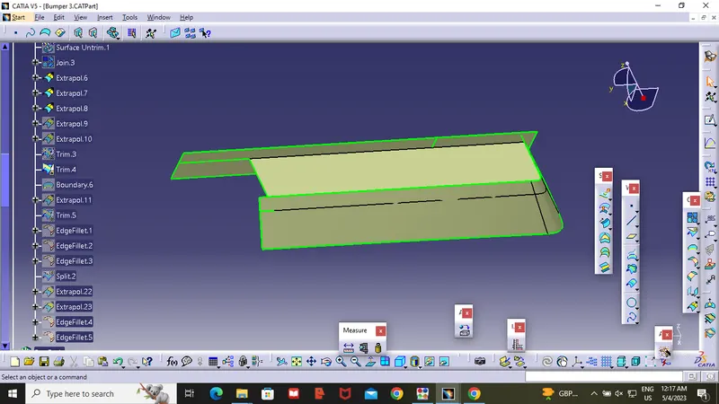
6) Extrapolate the B boundary surface up 5-6mm thickness.so it easy to get the final output of the component .
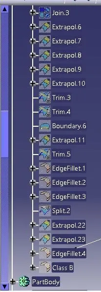
7)After compleating the B Surface the edges was filleted . and B surface was Complateded .
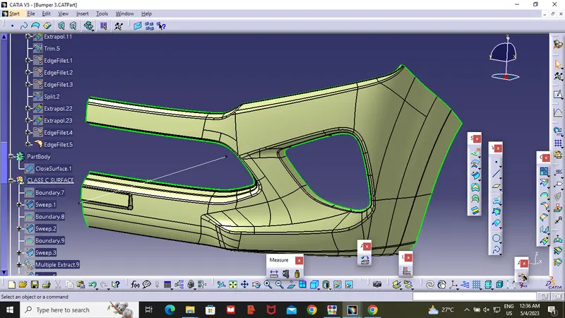
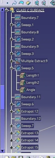
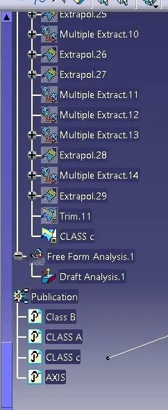
8) The next step is to create Class C Surface. Boundary was created on the Specified Region which would be later modeified with swept command .
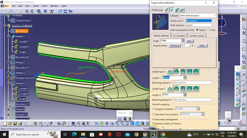
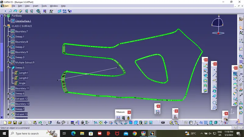
9) Some Regions were created by taking tooling axis and remaining regions were created by reference surface .
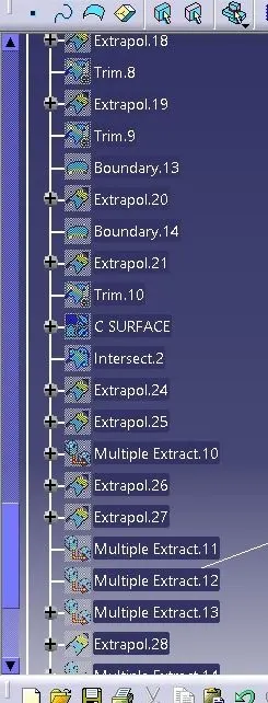
10)After that extrapolate the C surface and trim where ever required to joint the surface . As shown in top image .
11)By using extrapolate and trime command .C surface is created .and A and C surafce was Joind by using Joint Command .
12)There is some problem in the triming of class A,c and B. so we used intrection method to identify the problem and joined the surface .
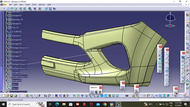
13) After getting Final Surface , get into part Design and select the shading with Edges option select customize view and then select closed surafce then select the final surafce .
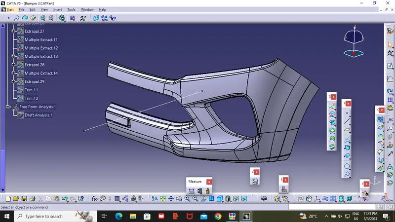
Draft Analysis
13)The Drafing Analysis was done on the solid body and it was aligning the compass with the tooling Axis .